2001 DODGE RAM length
[x] Cancel search: lengthPage 358 of 2889
BELT TENSIONERS - 5.9L
DIESEL
DESCRIPTION
Drive belts on all engines are equipped with a
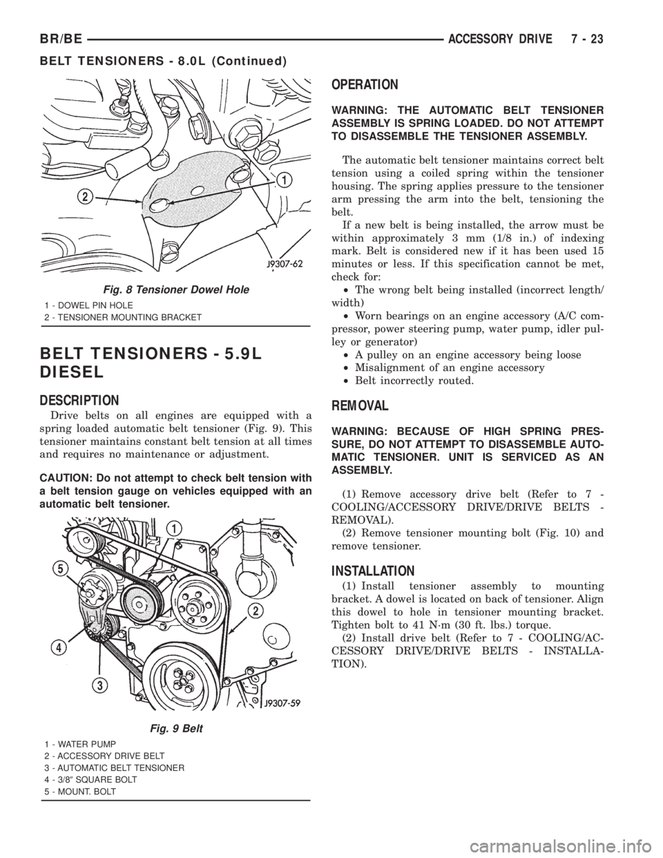
spring loaded automatic belt tensioner (Fig. 9). This
tensioner maintains constant belt tension at all times
and requires no maintenance or adjustment.
CAUTION: Do not attempt to check belt tension with
a belt tension gauge on vehicles equipped with an
automatic belt tensioner.
OPERATION
WARNING: THE AUTOMATIC BELT TENSIONER
ASSEMBLY IS SPRING LOADED. DO NOT ATTEMPT
TO DISASSEMBLE THE TENSIONER ASSEMBLY.
The automatic belt tensioner maintains correct belt
tension using a coiled spring within the tensioner
housing. The spring applies pressure to the tensioner
arm pressing the arm into the belt, tensioning the
belt.
If a new belt is being installed, the arrow must be
within approximately 3 mm (1/8 in.) of indexing
mark. Belt is considered new if it has been used 15
minutes or less. If this specification cannot be met,
check for:
²The wrong belt being installed (incorrect length/
width)
²Worn bearings on an engine accessory (A/C com-
pressor, power steering pump, water pump, idler pul-
ley or generator)
²A pulley on an engine accessory being loose
²Misalignment of an engine accessory
²Belt incorrectly routed.
REMOVAL
WARNING: BECAUSE OF HIGH SPRING PRES-
SURE, DO NOT ATTEMPT TO DISASSEMBLE AUTO-
MATIC TENSIONER. UNIT IS SERVICED AS AN
ASSEMBLY.
(1) Remove accessory drive belt (Refer to 7 -
COOLING/ACCESSORY DRIVE/DRIVE BELTS -
REMOVAL).
(2) Remove tensioner mounting bolt (Fig. 10) and
remove tensioner.
INSTALLATION
(1) Install tensioner assembly to mounting
bracket. A dowel is located on back of tensioner. Align
this dowel to hole in tensioner mounting bracket.
Tighten bolt to 41 N´m (30 ft. lbs.) torque.
(2) Install drive belt (Refer to 7 - COOLING/AC-
CESSORY DRIVE/DRIVE BELTS - INSTALLA-
TION).
Fig. 8 Tensioner Dowel Hole
1 - DOWEL PIN HOLE
2 - TENSIONER MOUNTING BRACKET
Fig. 9 Belt
1 - WATER PUMP
2 - ACCESSORY DRIVE BELT
3 - AUTOMATIC BELT TENSIONER
4 - 3/89SQUARE BOLT
5 - MOUNT. BOLT
BR/BEACCESSORY DRIVE 7 - 23
BELT TENSIONERS - 8.0L (Continued)
Page 362 of 2889
INSTALLATION
CAUTION: When installing the accessory drive belt,
the belt must be routed correctly. If not, engine may
overheat due to water pump rotating in wrong
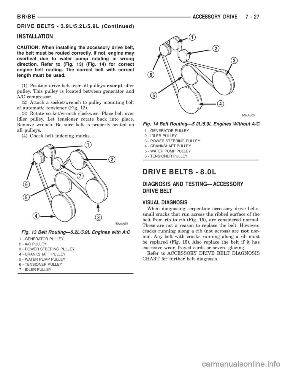
direction. Refer to (Fig. 13) (Fig. 14) for correct
engine belt routing. The correct belt with correct
length must be used.
(1) Position drive belt over all pulleysexceptidler
pulley. This pulley is located between generator and
A/C compressor.
(2) Attach a socket/wrench to pulley mounting bolt
of automatic tensioner (Fig. 12).
(3) Rotate socket/wrench clockwise. Place belt over
idler pulley. Let tensioner rotate back into place.
Remove wrench. Be sure belt is properly seated on
all pulleys.
(4) Check belt indexing marks. .
DRIVE BELTS - 8.0L
DIAGNOSIS AND TESTINGÐACCESSORY
DRIVE BELT
VISUAL DIAGNOSIS
When diagnosing serpentine accessory drive belts,
small cracks that run across the ribbed surface of the
belt from rib to rib (Fig. 15), are considered normal.
These are not a reason to replace the belt. However,
cracks running along a rib (not across) arenotnor-
mal. Any belt with cracks running along a rib must
be replaced (Fig. 15). Also replace the belt if it has
excessive wear, frayed cords or severe glazing.
Refer to ACCESSORY DRIVE BELT DIAGNOSIS
CHART for further belt diagnosis.
Fig. 13 Belt RoutingÐ5.2L/5.9L Engines with A/C
1 - GENERATOR PULLEY
2 - A/C PULLEY
3 - POWER STEERING PULLEY
4 - CRANKSHAFT PULLEY
5 - WATER PUMP PULLEY
6 - TENSIONER PULLEY
7 - IDLER PULLEY
Fig. 14 Belt RoutingÐ5.2L/5.9L Engines Without A/C
1 - GENERATOR PULLEY
2 - IDLER PULLEY
3 - POWER STEERING PULLEY
4 - CRANKSHAFT PULLEY
5 - WATER PUMP PULLEY
6 - TENSIONER PULLEY
BR/BEACCESSORY DRIVE 7 - 27
DRIVE BELTS - 3.9L/5.2L/5.9L (Continued)
Page 365 of 2889
REMOVAL
Drive belts are equipped with a spring loaded auto-
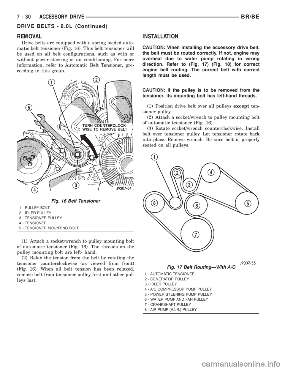
matic belt tensioner (Fig. 16). This belt tensioner will
be used on all belt configurations, such as with or
without power steering or air conditioning. For more
information, refer to Automatic Belt Tensioner, pro-
ceeding in this group.
(1) Attach a socket/wrench to pulley mounting bolt
of automatic tensioner (Fig. 16). The threads on the
pulley mounting bolt are left- hand.
(2) Relax the tension from the belt by rotating the
tensioner counterclockwise (as viewed from front)
(Fig. 16). When all belt tension has been relaxed,
remove belt from tensioner pulley first and other pul-
leys last.
INSTALLATION
CAUTION: When installing the accessory drive belt,
the belt must be routed correctly. If not, engine may
overheat due to water pump rotating in wrong
direction. Refer to (Fig. 17) (Fig. 18) for correct
engine belt routing. The correct belt with correct
length must be used.
CAUTION: If the pulley is to be removed from the
tensioner, its mounting bolt has left-hand threads.
(1) Position drive belt over all pulleysexceptten-
sioner pulley.
(2) Attach a socket/wrench to pulley mounting bolt
of automatic tensioner (Fig. 16).
(3) Rotate socket/wrench counterclockwise. Install
belt over tensioner pulley. Let tensioner rotate back
into place. Remove wrench. Be sure belt is properly
seated on all pulleys.
Fig. 16 Belt Tensioner
1 - PULLEY BOLT
2 - IDLER PULLEY
3 - TENSIONER PULLEY
4 - TENSIONER
5 - TENSIONER MOUNTING BOLT
Fig. 17 Belt RoutingÐWith A/C
1 - AUTOMATIC TENSIONER
2 - GENERATOR PULLEY
3 - IDLER PULLEY
4 - A/C COMPRESSOR PUMP PULLEY
5 - POWER STEERING PUMP PULLEY
6 - WATER PUMP AND FAN PULLEY
7 - CRANKSHAFT PULLEY
8 - AIR PUMP (A.I.R.) PULLEY
7 - 30 ACCESSORY DRIVEBR/BE
DRIVE BELTS - 8.0L (Continued)
Page 369 of 2889
INSTALLATION
CAUTION: When installing the accessory drive belt,
the belt must be routed correctly. If not, engine may
overheat due to water pump rotating in wrong
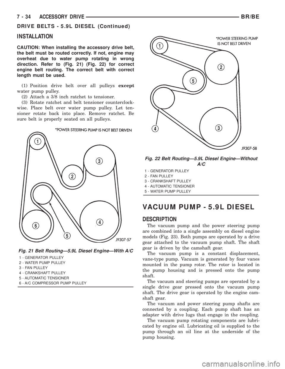
direction. Refer to (Fig. 21) (Fig. 22) for correct
engine belt routing. The correct belt with correct
length must be used.
(1) Position drive belt over all pulleysexcept
water pump pulley.
(2) Attach a 3/8 inch ratchet to tensioner.
(3) Rotate ratchet and belt tensioner counterclock-
wise. Place belt over water pump pulley. Let ten-
sioner rotate back into place. Remove ratchet. Be
sure belt is properly seated on all pulleys.
VACUUM PUMP - 5.9L DIESEL
DESCRIPTION
The vacuum pump and the power steering pump
are combined into a single assembly on diesel engine
models (Fig. 23). Both pumps are operated by a drive
gear attached to the vacuum pump shaft. The shaft
gear is driven by the camshaft gear.
The vacuum pump is a constant displacement,
vane-type pump. Vacuum is generated by four vanes
mounted in the pump rotor. The rotor is located in
the pump housing and is pressed onto the pump
shaft.
The vacuum and steering pumps are operated by a
single drive gear pressed onto the vacuum pump
shaft. The drive gear is operated by the engine cam-
shaft gear.
The vacuum and power steering pump shafts are
connected by a coupling. Each pump shaft has an
adapter with drive lugs that engage in the coupling.
The vacuum pump rotating components are lubri-
cated by engine oil. Lubricating oil is supplied to the
pump through an oil line at the underside of the
pump housing.
Fig. 21 Belt RoutingÐ5.9L Diesel EngineÐWith A/C
1 - GENERATOR PULLEY
2 - WATER PUMP PULLEY
3 - FAN PULLEY
4 - CRANKSHAFT PULLEY
5 - AUTOMATIC TENSIONER
6 - A/C COMPRESSOR PUMP PULLEY
Fig. 22 Belt RoutingÐ5.9L Diesel EngineÐWithout
A/C
1 - GENERATOR PULLEY
2 - FAN PULLEY
3 - CRANKSHAFT PULLEY
4 - AUTOMATIC TENSIONER
5 - WATER PUMP PULLEY
7 - 34 ACCESSORY DRIVEBR/BE
DRIVE BELTS - 5.9L DIESEL (Continued)
Page 386 of 2889
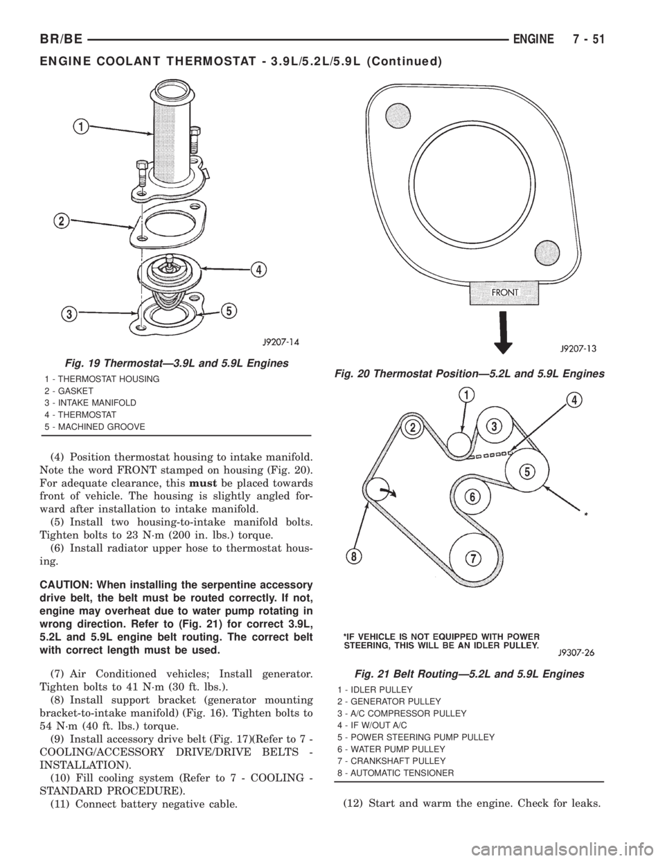
(4) Position thermostat housing to intake manifold.
Note the word FRONT stamped on housing (Fig. 20).
For adequate clearance, thismustbe placed towards
front of vehicle. The housing is slightly angled for-
ward after installation to intake manifold.
(5) Install two housing-to-intake manifold bolts.
Tighten bolts to 23 N´m (200 in. lbs.) torque.
(6) Install radiator upper hose to thermostat hous-
ing.
CAUTION: When installing the serpentine accessory
drive belt, the belt must be routed correctly. If not,
engine may overheat due to water pump rotating in
wrong direction. Refer to (Fig. 21) for correct 3.9L,
5.2L and 5.9L engine belt routing. The correct belt
with correct length must be used.
(7) Air Conditioned vehicles; Install generator.
Tighten bolts to 41 N´m (30 ft. lbs.).
(8) Install support bracket (generator mounting
bracket-to-intake manifold) (Fig. 16). Tighten bolts to
54 N´m (40 ft. lbs.) torque.
(9) Install accessory drive belt (Fig. 17)(Refer to 7 -
COOLING/ACCESSORY DRIVE/DRIVE BELTS -
INSTALLATION).
(10) Fill cooling system (Refer to 7 - COOLING -
STANDARD PROCEDURE).
(11) Connect battery negative cable.(12) Start and warm the engine. Check for leaks.
Fig. 19 ThermostatÐ3.9L and 5.9L Engines
1 - THERMOSTAT HOUSING
2 - GASKET
3 - INTAKE MANIFOLD
4 - THERMOSTAT
5 - MACHINED GROOVEFig. 20 Thermostat PositionÐ5.2L and 5.9L Engines
Fig. 21 Belt RoutingÐ5.2L and 5.9L Engines
1 - IDLER PULLEY
2 - GENERATOR PULLEY
3 - A/C COMPRESSOR PULLEY
4 - IF W/OUT A/C
5 - POWER STEERING PUMP PULLEY
6 - WATER PUMP PULLEY
7 - CRANKSHAFT PULLEY
8 - AUTOMATIC TENSIONER
BR/BEENGINE 7 - 51
ENGINE COOLANT THERMOSTAT - 3.9L/5.2L/5.9L (Continued)
Page 413 of 2889
CAUTION: When installing the serpentine accessory
drive belt, the belt must be routed correctly. If not,
the engine may overheat due to the water pump
rotating in the wrong direction (Refer to 7 - COOL-
ING/ACCESSORY DRIVE/DRIVE BELTS - INSTALLA-
TION). The correct belt with the correct length must
be used.(12) Install air cleaner assembly.
(13) Install upper radiator hose to radiator.
(14) Connect throttle cable to clip at radiator fan
shroud.
(15) Connect wiring harness to A/C compressor.
(16) Fill cooling system (Refer to 7 - COOLING -
STANDARD PROCEDURE).
(17) Start and warm the engine. Check for leaks.
INSTALLATIONÐWATER PUMP BYPASS HOSE
WITHOUT AIR CONDITIONING
(1) Position bypass hose clamps to the center of
hose.
(2) Install bypass hose to engine.
(3) Secure both hose clamps.
(4) Fill cooling system (Refer to 7 - COOLING -
STANDARD PROCEDURE).
(5) Start and warm the engine. Check for leaks.
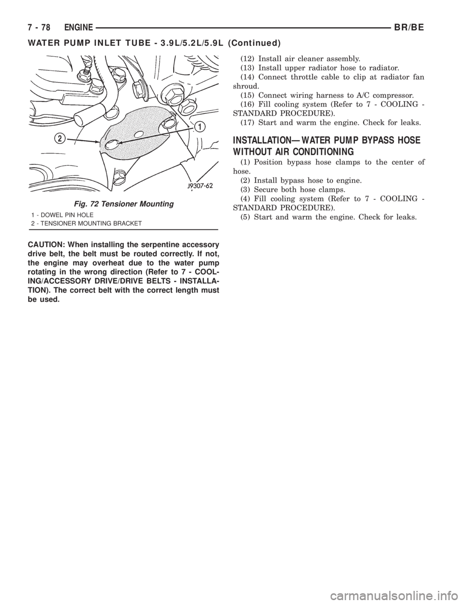
Fig. 72 Tensioner Mounting
1 - DOWEL PIN HOLE
2 - TENSIONER MOUNTING BRACKET
7 - 78 ENGINEBR/BE
WATER PUMP INLET TUBE - 3.9L/5.2L/5.9L (Continued)
Page 428 of 2889
commercial radio stations in both the Amplitude
Modulating (AM) and Frequency Modulating (FM)
frequency ranges. These electromagnetic radio fre-
quency signals induce small electrical modulations
into the antenna as they move past the mast. The
antenna body transfers the weak electromagnetic
radio waves induced into the rigid antenna mast into
the center conductor of the flexible primary antenna
coaxial cable. The braided outer shield of the
antenna coaxial cable is grounded through both the
antenna body and the radio chassis, effectively
shielding the radio waves as they are conducted to
the radio. The radio then tunes and amplifies the
weak radio signals into stronger electrical signals in
order to operate the audio system speakers.
The antenna body includes an integral flange that
mates with and grounds the antenna body to the
underside of the fender panel sheet metal. Above the
fender panel, the antenna body has a short nipple
that is externally threaded to accept the antenna cap
nut. Inside the nipple is a plastic insulator tube, and
inside this insulator is an internally threaded metal
receptacle that accepts the adapter stud on the bot-
tom of the antenna mast. The antenna adapter
serves as an above fender interface to mount and
secure the antenna body to the vehicle. The antenna
adapter is a black molded plastic component that
provides a functional transition between the top of
the fender and the antenna cap nut, while concealing
the edges of the antenna mounting hole and protect-
ing the painted finish of the fender from marring as
the antenna cap nut is tightened. The adapter is
installed over and shrouds the threaded nipple of the
antenna body, which is installed from under and pro-
trudes through the top of the mounting hole in the
fender. The antenna cap nut is installed on top of the
antenna adapter and tightened onto the external
threads of the antenna body nipple to effectively
secure and ground the antenna body to the fender.
Three notches on the outer circumference of the cap
nut are engaged by matching projections of an
antenna nut wrench (Special Tool C-4816) to facili-
tate the removal and installation of this special fas-
tener. Proper tightening of the antenna cap nut is
critical to ensuring proper grounding of the antenna
body to the fender sheet metal, which is necessary
for clear radio signal reception.
A short length of coaxial cable serves as the pri-
mary antenna cable. The center conductor of the
cable is connected to the antenna mast receptacle.
The outer wire mesh of the cable is connected to and
grounded through the antenna body. One end of the
primary antenna cable is securely crimped to the
lower end of the antenna body, while the opposite
end features a simple push/pull-type male coaxial
cable connector that serves as the in-line connector tothe instrument panel (secondary) antenna coaxial
cable. The primary coaxial cable includes a grommet
that seals the cable to an entry hole in the right cowl
side outer panel where the cable passes into the pas-
senger compartment of the vehicle. The secondary
antenna cable has a push/pull-type male coaxial
cable connector on the radio end, and a push/pull-
type female coaxial cable connector on the opposite
end, which serves as the in-line connector to the pri-
mary antenna cable. In the passenger compartment
the primary cable is routed to the lower right side of
the instrument panel, where it is connected to the
secondary instrument panel antenna cable. The
instrument panel antenna cable is routed near the
instrument panel wire harness through the instru-
ment panel to the radio and is secured to the instru-
ment panel structural support with small metal
push-on retainers. This two-piece antenna cable
arrangement allows the instrument panel or the
antenna body and cable to be removed or installed
without disturbing the radio.
DIAGNOSIS AND TESTING
DIAGNOSIS AND TESTING - ANTENNA
WARNING: ON VEHICLES EQUIPPED WITH AIR-
BAGS, REFER TO ELECTRICAL, RESTRAINTS
BEFORE ATTEMPTING ANY STEERING WHEEL,
STEERING COLUMN, OR INSTRUMENT PANEL
COMPONENT DIAGNOSIS OR SERVICE. FAILURE
TO TAKE THE PROPER PRECAUTIONS COULD
RESULT IN ACCIDENTAL AIRBAG DEPLOYMENT
AND POSSIBLE PERSONAL INJURY.
The following four tests are used to diagnose the
antenna with an ohmmeter:
²Test 1- Mast to ground test
²Test 2- Tip-of-mast to tip-of-conductor test
²Test 3- Body ground to battery ground test
²Test 4- Body ground to coaxial shield test.
The ohmmeter test lead connections for each test
are shown in Antenna Tests (Fig. 1).
NOTE: This model has a two-piece antenna coaxial
cable. Tests 2 and 4 must be conducted in two
steps to isolate a coaxial cable problem; from the
coaxial cable connection under the right end of the
instrument panel near the right cowl side inner
panel to the antenna base, and then from the coax-
ial cable connection to the radio receiver chassis
connection.
BR/BEAUDIO 8A - 5
ANTENNA BODY & CABLE (Continued)
Page 430 of 2889
(3) Remove the foam tape to access the coaxial
cable connector. Disconnect the connector by pulling
it apart while twisting the metal connector halves.
Do not pull on the cable.
(4) Securely tie a suitable length of cord or twine
to the antenna half of the coaxial cable connector.
This cord will be used to pull or ªfishº the cable back
into position during installation.
(5) Reach above the Powertrain Control Module
(PCM) on the right side of the dash panel in the
engine compartment to disengage the antenna coax-
ial cable grommet from the hole in the dash panel
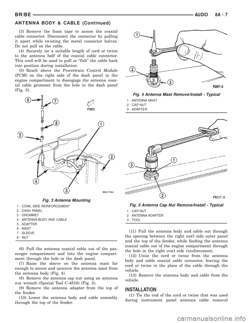
(Fig. 3).
(6) Pull the antenna coaxial cable out of the pas-
senger compartment and into the engine compart-
ment through the hole in the dash panel.
(7) Raise the sleeve on the antenna mast far
enough to access and unscrew the antenna mast from
the antenna body (Fig. 4).
(8) Remove the antenna cap nut using an antenna
nut wrench (Special Tool C-4816) (Fig. 5).
(9) Remove the antenna adapter from the top of
the fender.
(10) Lower the antenna body and cable assembly
through the top of the fender.(11) Pull the antenna body and cable out through
the opening between the right cowl side outer panel
and the top of the fender, while feeding the antenna
coaxial cable out of the engine compartment through
the hole in the right cowl side reinforcement.
(12) Untie the cord or twine from the antenna
body and cable coaxial cable connector, leaving the
cord or twine in the place of the cable through the
vehicle.
(13) Remove the antenna body and cable from the
vehicle.
INSTALLATION
(1) Tie the end of the cord or twine that was used
during instrument panel antenna cable removal
Fig. 3 Antenna Mounting
1 - COWL SIDE REINFORCEMENT
2 - DASH PANEL
3 - GROMMET
4 - ANTENNA BODY AND CABLE
5 - ADAPTER
6 - MAST
7 - SLEEVE
8 - NUT
Fig. 4 Antenna Mast Remove/Install - Typical
1 - ANTENNA MAST
2 - CAP NUT
3 - ADAPTER
Fig. 5 Antenna Cap Nut Remove/Install - Typical
1 - CAP NUT
2 - ANTENNA ADAPTER
3 - TOOL
BR/BEAUDIO 8A - 7
ANTENNA BODY & CABLE (Continued)