2001 DODGE RAM check engine light
[x] Cancel search: check engine lightPage 1966 of 2889
(17) Raise transmission slightly with service jack
to relieve load on crossmember and supports.
(18) Remove bolts securing rear support and cush-
ion to transmission and crossmember. Raise trans-
mission slightly, slide exhaust hanger arm from
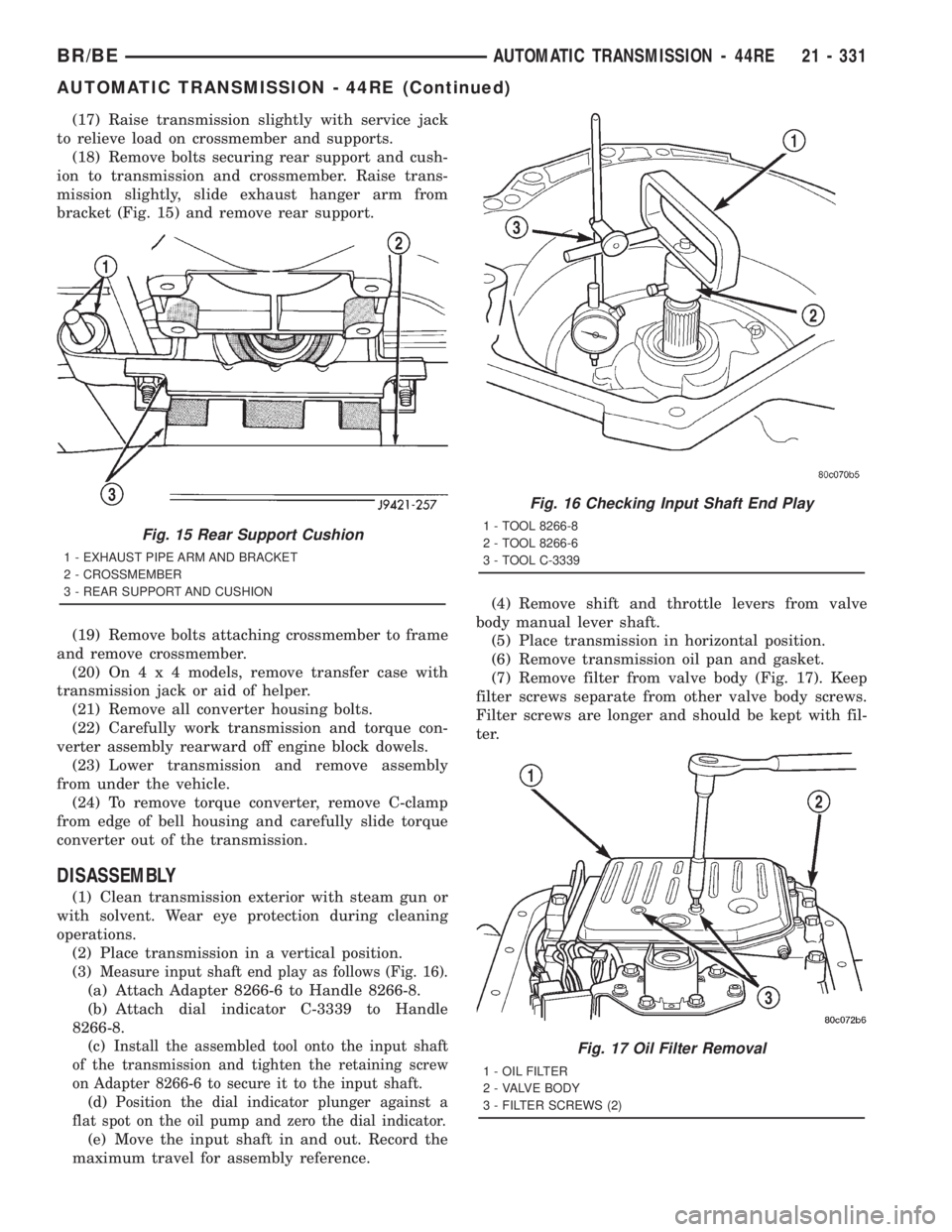
bracket (Fig. 15) and remove rear support.
(19) Remove bolts attaching crossmember to frame
and remove crossmember.
(20) On4x4models, remove transfer case with
transmission jack or aid of helper.
(21) Remove all converter housing bolts.
(22) Carefully work transmission and torque con-
verter assembly rearward off engine block dowels.
(23) Lower transmission and remove assembly
from under the vehicle.
(24) To remove torque converter, remove C-clamp
from edge of bell housing and carefully slide torque
converter out of the transmission.
DISASSEMBLY
(1) Clean transmission exterior with steam gun or
with solvent. Wear eye protection during cleaning
operations.
(2) Place transmission in a vertical position.
(3)
Measure input shaft end play as follows (Fig. 16).
(a) Attach Adapter 8266-6 to Handle 8266-8.
(b) Attach dial indicator C-3339 to Handle
8266-8.
(c)
Install the assembled tool onto the input shaft
of the transmission and tighten the retaining screw
on Adapter 8266-6 to secure it to the input shaft.
(d)Position the dial indicator plunger against a
flat spot on the oil pump and zero the dial indicator.
(e) Move the input shaft in and out. Record the
maximum travel for assembly reference.(4) Remove shift and throttle levers from valve
body manual lever shaft.
(5) Place transmission in horizontal position.
(6) Remove transmission oil pan and gasket.
(7) Remove filter from valve body (Fig. 17). Keep
filter screws separate from other valve body screws.
Filter screws are longer and should be kept with fil-
ter.
Fig. 15 Rear Support Cushion
1 - EXHAUST PIPE ARM AND BRACKET
2 - CROSSMEMBER
3 - REAR SUPPORT AND CUSHION
Fig. 16 Checking Input Shaft End Play
1 - TOOL 8266-8
2 - TOOL 8266-6
3 - TOOL C-3339
Fig. 17 Oil Filter Removal
1 - OIL FILTER
2 - VALVE BODY
3 - FILTER SCREWS (2)
BR/BEAUTOMATIC TRANSMISSION - 44RE 21 - 331
AUTOMATIC TRANSMISSION - 44RE (Continued)
Page 1979 of 2889
INSTALLATION
(1) Check torque converter hub and hub drive
notches for sharp edges burrs, scratches, or nicks.
Polish the hub and notches with 320/400 grit paper
and crocus cloth if necessary. The hub must be
smooth to avoid damaging pump seal at installation.
(2) Lubricate pocket in the rear oil pump seal lip
with transmission fluid.
(3) Lubricate converter pilot hub of the crankshaft
with a light coating of MopartHigh Temp Grease.
(4) Align and install converter in oil pump.
(5) Carefully insert converter in oil pump. Then
rotate converter back and forth until fully seated in
pump gears.
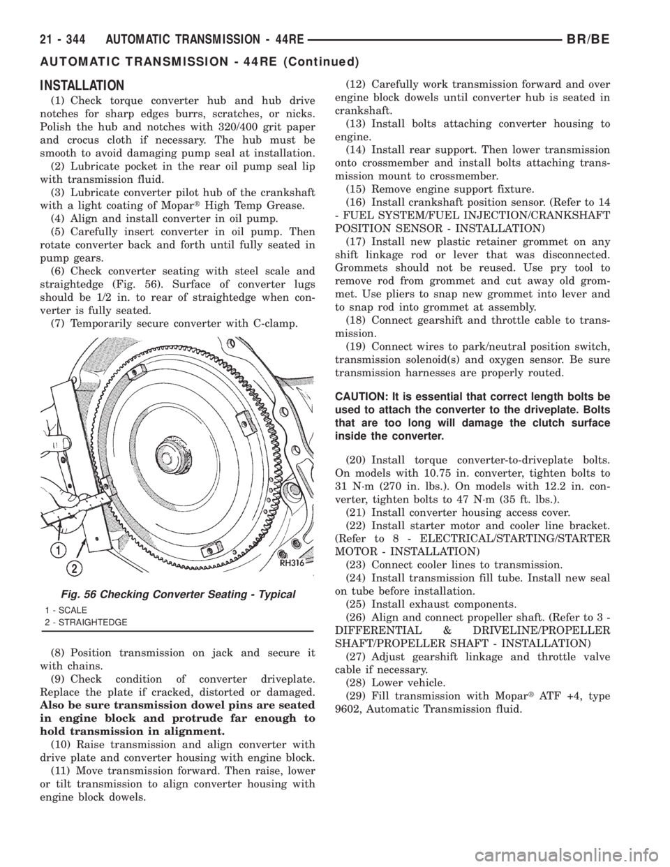
(6) Check converter seating with steel scale and
straightedge (Fig. 56). Surface of converter lugs
should be 1/2 in. to rear of straightedge when con-
verter is fully seated.
(7) Temporarily secure converter with C-clamp.
(8) Position transmission on jack and secure it
with chains.
(9) Check condition of converter driveplate.
Replace the plate if cracked, distorted or damaged.
Also be sure transmission dowel pins are seated
in engine block and protrude far enough to
hold transmission in alignment.
(10) Raise transmission and align converter with
drive plate and converter housing with engine block.
(11) Move transmission forward. Then raise, lower
or tilt transmission to align converter housing with
engine block dowels.(12) Carefully work transmission forward and over
engine block dowels until converter hub is seated in
crankshaft.
(13) Install bolts attaching converter housing to
engine.
(14) Install rear support. Then lower transmission
onto crossmember and install bolts attaching trans-
mission mount to crossmember.
(15) Remove engine support fixture.
(16) Install crankshaft position sensor. (Refer to 14
- FUEL SYSTEM/FUEL INJECTION/CRANKSHAFT
POSITION SENSOR - INSTALLATION)
(17) Install new plastic retainer grommet on any
shift linkage rod or lever that was disconnected.
Grommets should not be reused. Use pry tool to
remove rod from grommet and cut away old grom-
met. Use pliers to snap new grommet into lever and
to snap rod into grommet at assembly.
(18) Connect gearshift and throttle cable to trans-
mission.
(19) Connect wires to park/neutral position switch,
transmission solenoid(s) and oxygen sensor. Be sure
transmission harnesses are properly routed.
CAUTION: It is essential that correct length bolts be
used to attach the converter to the driveplate. Bolts
that are too long will damage the clutch surface
inside the converter.
(20) Install torque converter-to-driveplate bolts.
On models with 10.75 in. converter, tighten bolts to
31 N´m (270 in. lbs.). On models with 12.2 in. con-
verter, tighten bolts to 47 N´m (35 ft. lbs.).
(21) Install converter housing access cover.
(22) Install starter motor and cooler line bracket.
(Refer to 8 - ELECTRICAL/STARTING/STARTER
MOTOR - INSTALLATION)
(23) Connect cooler lines to transmission.
(24) Install transmission fill tube. Install new seal
on tube before installation.
(25) Install exhaust components.
(26) Align and connect propeller shaft. (Refer to 3 -
DIFFERENTIAL & DRIVELINE/PROPELLER
SHAFT/PROPELLER SHAFT - INSTALLATION)
(27) Adjust gearshift linkage and throttle valve
cable if necessary.
(28) Lower vehicle.
(29) Fill transmission with MopartATF +4, type
9602, Automatic Transmission fluid.
Fig. 56 Checking Converter Seating - Typical
1 - SCALE
2 - STRAIGHTEDGE
21 - 344 AUTOMATIC TRANSMISSION - 44REBR/BE
AUTOMATIC TRANSMISSION - 44RE (Continued)
Page 2138 of 2889
(12) Disconnect wires from park/neutral position
switch and transmission solenoid.
(13) Disconnect gearshift rod and torque shaft
assembly from transmission.
(14) Disconnect throttle valve cable from transmis-
sion bracket and throttle valve lever.
(15) On4x4models, disconnect shift rod from
transfer case shift lever.
(16)
Support rear of engine with safety stand or jack.
(17) Raise transmission slightly with service jack
to relieve load on crossmember and supports.
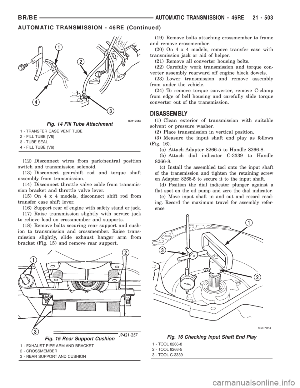
(18) Remove bolts securing rear support and cush-
ion to transmission and crossmember. Raise trans-
mission slightly, slide exhaust hanger arm from
bracket (Fig. 15) and remove rear support.(19) Remove bolts attaching crossmember to frame
and remove crossmember.
(20) On4x4models, remove transfer case with
transmission jack or aid of helper.
(21) Remove all converter housing bolts.
(22) Carefully work transmission and torque con-
verter assembly rearward off engine block dowels.
(23) Lower transmission and remove assembly
from under the vehicle.
(24) To remove torque converter, remove C-clamp
from edge of bell housing and carefully slide torque
converter out of the transmission.
DISASSEMBLY
(1) Clean exterior of transmission with suitable
solvent or pressure washer.
(2) Place transmission in vertical position.
(3) Measure the input shaft end play as follows
(Fig. 16).
(a) Attach Adapter 8266-5 to Handle 8266-8.
(b) Attach dial indicator C-3339 to Handle
8266-8.
(c)
Install the assembled tool onto the input shaft
of the transmission and tighten the retaining screw
on Adapter 8266-5 to secure it to the input shaft.
(d)Position the dial indicator plunger against a
flat spot on the oil pump and zero the dial indicator.
(e)Move input shaft in and out and record read-
ing. Record the maximum travel for assembly refer-
ence
Fig. 14 Fill Tube Attachment
1 - TRANSFER CASE VENT TUBE
2 - FILL TUBE (V8)
3 - TUBE SEAL
4 - FILL TUBE (V6)
Fig. 15 Rear Support Cushion
1 - EXHAUST PIPE ARM AND BRACKET
2 - CROSSMEMBER
3 - REAR SUPPORT AND CUSHION
Fig. 16 Checking Input Shaft End Play
1 - TOOL 8266-8
2 - TOOL 8266-5
3 - TOOL C-3339
BR/BEAUTOMATIC TRANSMISSION - 46RE 21 - 503
AUTOMATIC TRANSMISSION - 46RE (Continued)
Page 2309 of 2889
(12) Disconnect wires from park/neutral position
switch and transmission solenoid.
(13) Disconnect gearshift rod and torque shaft
assembly from transmission.
(14) Disconnect throttle valve cable from transmis-
sion bracket and throttle valve lever.
(15) On4x4models, disconnect shift rod from
transfer case shift lever.
(16)
Support rear of engine with safety stand or jack.
(17) Raise transmission slightly with service jack
to relieve load on crossmember and supports.
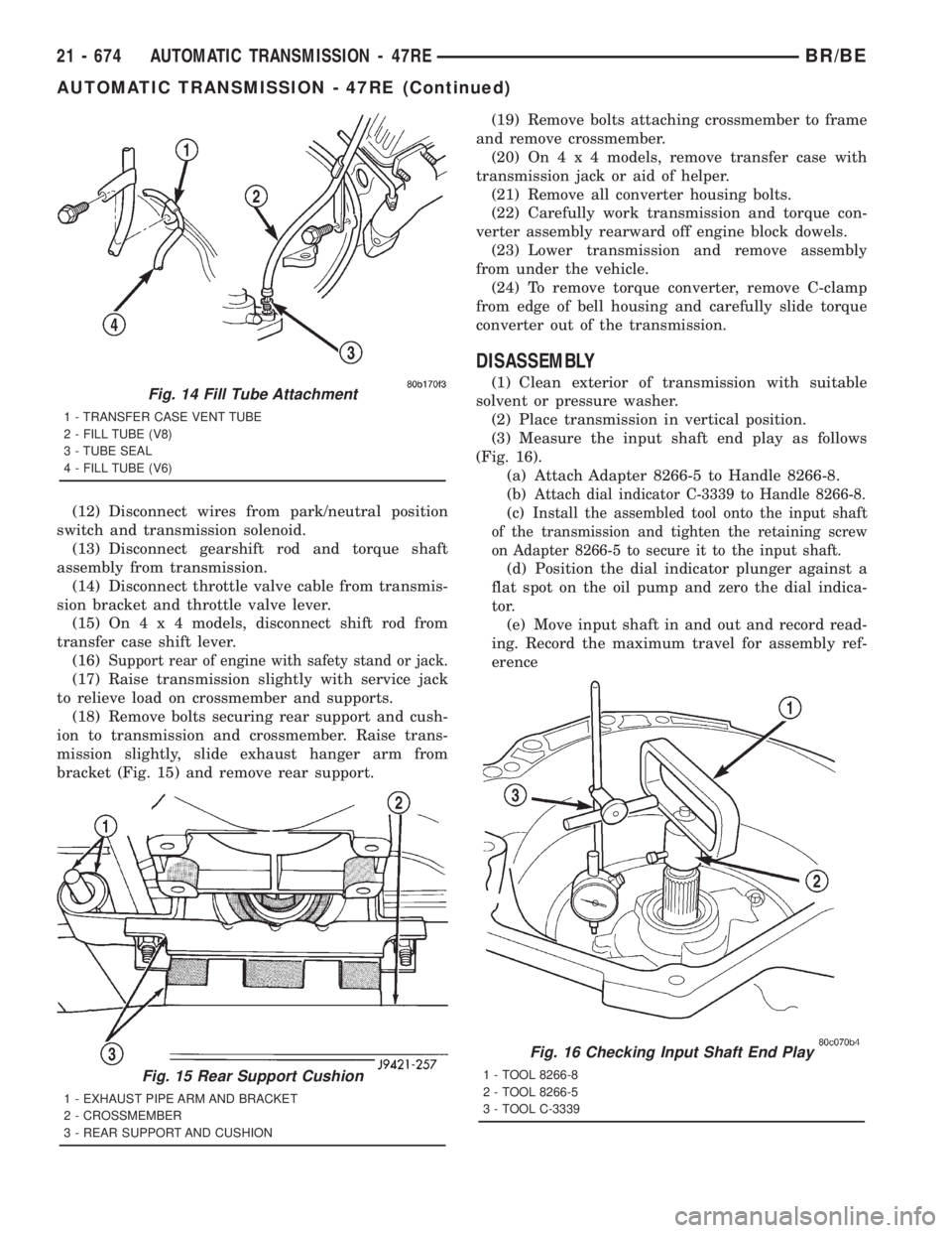
(18) Remove bolts securing rear support and cush-
ion to transmission and crossmember. Raise trans-
mission slightly, slide exhaust hanger arm from
bracket (Fig. 15) and remove rear support.(19) Remove bolts attaching crossmember to frame
and remove crossmember.
(20) On4x4models, remove transfer case with
transmission jack or aid of helper.
(21) Remove all converter housing bolts.
(22) Carefully work transmission and torque con-
verter assembly rearward off engine block dowels.
(23) Lower transmission and remove assembly
from under the vehicle.
(24) To remove torque converter, remove C-clamp
from edge of bell housing and carefully slide torque
converter out of the transmission.
DISASSEMBLY
(1) Clean exterior of transmission with suitable
solvent or pressure washer.
(2) Place transmission in vertical position.
(3) Measure the input shaft end play as follows
(Fig. 16).
(a) Attach Adapter 8266-5 to Handle 8266-8.
(b)
Attach dial indicator C-3339 to Handle 8266-8.
(c)Install the assembled tool onto the input shaft
of the transmission and tighten the retaining screw
on Adapter 8266-5 to secure it to the input shaft.
(d) Position the dial indicator plunger against a
flat spot on the oil pump and zero the dial indica-
tor.
(e) Move input shaft in and out and record read-
ing. Record the maximum travel for assembly ref-
erence
Fig. 14 Fill Tube Attachment
1 - TRANSFER CASE VENT TUBE
2 - FILL TUBE (V8)
3 - TUBE SEAL
4 - FILL TUBE (V6)
Fig. 15 Rear Support Cushion
1 - EXHAUST PIPE ARM AND BRACKET
2 - CROSSMEMBER
3 - REAR SUPPORT AND CUSHION
Fig. 16 Checking Input Shaft End Play
1 - TOOL 8266-8
2 - TOOL 8266-5
3 - TOOL C-3339
21 - 674 AUTOMATIC TRANSMISSION - 47REBR/BE
AUTOMATIC TRANSMISSION - 47RE (Continued)
Page 2323 of 2889
(a) Loosen locknut on each band adjusting screw
4-5 turns.
(b) Tighten both adjusting screws to 8 N´m (72
in. lbs.).
(c) Back off front band adjusting screw 1-7/8
turns.
(d) Back off rear band adjusting screw 3 turns.
(e) Hold each adjusting screw in position and
tighten locknut to 34 N´m (25 ft. lbs.) torque.
(2) Install magnet in oil pan. Magnet seats on
small protrusion at corner of pan.
(3) Position new oil pan gasket on case and install
oil pan. Tighten pan bolts to 17 N´m (13 ft. lbs.).
(4) Install throttle valve and shift selector levers
on valve body manual lever shaft.
(5) Apply small quantity of dielectric grease to ter-
minal pins of solenoid case connector and neutral
switch.
(6) Fill transmission with recommended fluid.
INSTALLATION
(1) Check torque converter hub and hub drive
notches for sharp edges burrs, scratches, or nicks.
Polish the hub and notches with 320/400 grit paper
and crocus cloth if necessary. The hub must be
smooth to avoid damaging pump seal at installation.
(2) Lubricate pocket in the rear oil pump seal lip
with transmission fluid.
(3) Lubricate converter pilot hub of the crankshaft
with a light coating of MopartHigh Temp Grease.
(4) Align and install converter in oil pump.
(5) Carefully insert converter in oil pump. Then
rotate converter back and forth until fully seated in
pump gears.
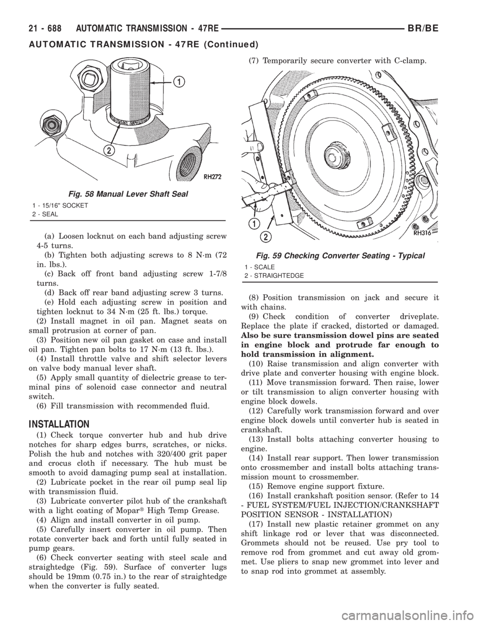
(6) Check converter seating with steel scale and
straightedge (Fig. 59). Surface of converter lugs
should be 19mm (0.75 in.) to the rear of straightedge
when the converter is fully seated.(7) Temporarily secure converter with C-clamp.
(8) Position transmission on jack and secure it
with chains.
(9) Check condition of converter driveplate.
Replace the plate if cracked, distorted or damaged.
Also be sure transmission dowel pins are seated
in engine block and protrude far enough to
hold transmission in alignment.
(10) Raise transmission and align converter with
drive plate and converter housing with engine block.
(11) Move transmission forward. Then raise, lower
or tilt transmission to align converter housing with
engine block dowels.
(12) Carefully work transmission forward and over
engine block dowels until converter hub is seated in
crankshaft.
(13) Install bolts attaching converter housing to
engine.
(14) Install rear support. Then lower transmission
onto crossmember and install bolts attaching trans-
mission mount to crossmember.
(15) Remove engine support fixture.
(16) Install crankshaft position sensor. (Refer to 14
- FUEL SYSTEM/FUEL INJECTION/CRANKSHAFT
POSITION SENSOR - INSTALLATION)
(17) Install new plastic retainer grommet on any
shift linkage rod or lever that was disconnected.
Grommets should not be reused. Use pry tool to
remove rod from grommet and cut away old grom-
met. Use pliers to snap new grommet into lever and
to snap rod into grommet at assembly.
Fig. 58 Manual Lever Shaft Seal
1 - 15/16©© SOCKET
2 - SEAL
Fig. 59 Checking Converter Seating - Typical
1 - SCALE
2 - STRAIGHTEDGE
21 - 688 AUTOMATIC TRANSMISSION - 47REBR/BE
AUTOMATIC TRANSMISSION - 47RE (Continued)
Page 2734 of 2889
A/C Diagnosis
Condition Possible Causes Correction
LOW SIDE PRESSURE
IS NORMAL OR
SLIGHTLY HIGH, AND
HIGH SIDE PRESSURE
IS TOO HIGH.1. Condenser air flow
restricted.1. Check the condenser for damaged fins, foreign objects
obstructing air flow through the condenser fins, and
missing or improperly installed air seals. Refer to Cooling
for more information on air seals. Clean, repair, or replace
components as required.
2. Inoperative cooling
fan.2. Refer to Cooling for more information. Test the cooling
fan and replace, if required.
3. Refrigerant system
overcharged.3. (Refer to Plumbing/Standard Procedure - Refrigerant
System Charge) in this group. Recover the refrigerant
from the refrigerant system. Charge the refrigerant
system to the proper level, if required.
4. Air in the refrigerant
system.4. (Refer to Plumbing/Diagnosis and Testing - Refrigerant
System Leaks) in this group. Test the refrigerant system
for leaks. Repair, evacuate and charge the refrigerant
system, if required.
5. Engine overheating. 5. Refer to Cooling for more information. Test the cooling
system and repair, if required.
LOW SIDE PRESSURE
IS TOO HIGH, AND
HIGH SIDE PRESSURE
IS TOO LOW.1. Accessory drive belt
slipping.1. Refer to Cooling for more information. Inspect the
accessory drive belt condition and tension. Tighten or
replace the accessory drive belt, if required.
2. A/C orifice tube not
installed.2. (Refer to Plumbing/A/C Orifice Tube/Diagnosis and
Testing) in this group. Replace the liquid line, if required.
3. Faulty a/c compressor. 3. (Refer to Plumbing/A/C Compressor/ Removal/
Installation) in this group. Replace the compressor, if
required.
LOW SIDE PRESSURE
IS TOO LOW, AND HIGH
SIDE PRESSURE IS
TOO HIGH.1. Restricted refrigerant
flow through the
refrigerant lines.1. (Refer to Plumbing/Caution - Refrigerant Hoses/Lines/
Tubes Precautions) in this group. Inspect the refrigerant
lines for kinks, tight bends or improper routing. Correct
the routing or replace the refrigerant line, if required.
2. Restricted refrigerant
flow through the a/c
orifice tube.2. (Refer to Plumbing/A/C Orifice Tube/Diagnosis and
Testing) in this group. Replace the liquid line, if required.
3. Restricted refrigerant
flow through the a/c
condenser.3. (Refer to Plumbing/A/C Condenser/ Removal/
Installation) in this group. Replace the restricted a/c
condenser, if required.
BR/BEHEATING & AIR CONDITIONING 24 - 5
HEATING & AIR CONDITIONING (Continued)
Page 2735 of 2889
DIAGNOSIS AND TESTING - HEATER
PERFORMANCE
Before performing the following tests, refer to Cool-
ing for the procedures to check the engine coolant
level and flow, engine coolant reserve/recovery sys-
tem operation, accessory drive belt condition and ten-
sion, radiator air flow and the fan drive operation.
Also be certain that the accessory vacuum supply
line is connected at the engine vacuum source.
MAXIMUM HEATER OUTPUT
Engine coolant is delivered to the heater core
through two heater hoses. With the engine idling atnormal operating temperature, set the temperature
control knob in the full hot position, the mode control
switch knob in the floor position, and the blower
motor switch knob in the highest speed position.
Using a test thermometer, check the temperature of
the air being discharged at the HVAC housing floor
outlets. Compare the test thermometer reading to the
Temperature Reference chart.
Temperature Reference
Ambient Air Temperature15.5É C
(60É F)21.1É C
(70É F)26.6É C
(80É F)32.2É C
(90É F)
Minimum Air Temperature at
Floor Outlet62.2É C
(144É F)63.8É C
(147É F)65.5É C
(150É F)67.2É C
(153É F)
If the floor outlet air temperature is too low, refer
to Cooling to check the engine coolant temperature
specifications. Both of the heater hoses should be hot
to the touch. The coolant return heater hose should
be slightly cooler than the coolant supply heater
hose. If the return hose is much cooler than the sup-
ply hose, locate and repair the engine coolant flow
obstruction in the cooling system. Refer to Cooling
for the procedures.
An alternate method of checking heater perfor-
mance is to use a DRBIIItscan tool to monitor the
engine coolant temperature. The floor outlet air tem-
perature reading should be no more than 4.5É C (40É
F) lower than the engine coolant temperature read-
ing.
OBSTRUCTED COOLANT FLOW Possible loca-
tions or causes of obstructed coolant flow:
²Faulty water pump.
²Faulty thermostat.
²Pinched or kinked heater hoses.
²Improper heater hose routing.
²Plugged heater hoses or supply and return ports
at the cooling system connections.
²A plugged heater core.If proper coolant flow through the cooling system is
verified, and heater outlet air temperature is still
low, a mechanical problem may exist.
MECHANICAL PROBLEMS Possible locations or
causes of insufficient heat:
²An obstructed cowl air intake.
²Obstructed heater system outlets.
²A faulty, obstructed or improperly installed
blend door.
²A faulty blower system.
²A faulty a/c heater control.
TEMPERATURE CONTROL
If the heater outlet air temperature cannot be
adjusted with the temperature control knob on the
a/c heater control panel, the following could require
service:
²A faulty a/c heater control.
²A faulty blend door actuator.
²A faulty, obstructed or improperly installed
blend door.
²An obstructed cowl air intake.
²The engine cooling system.
24 - 6 HEATING & AIR CONDITIONINGBR/BE
HEATING & AIR CONDITIONING (Continued)
Page 2745 of 2889
INSPECTION
Examine the friction surfaces of the clutch pulley
and the front plate for wear. The pulley and front
plate should be replaced if there is excessive wear or
scoring.
If the friction surfaces are oily, inspect the shaft
and nose area of the compressor for oil. Remove the
felt from the front cover. If the felt is saturated with
oil, the shaft seal is leaking and the compressor must
be replaced.
Check the clutch pulley bearing for roughness or
excessive leakage of grease. Replace the bearing, if
required.
INSTALLATION
(1) Install the clutch field coil and snap ring.
(2) Install the clutch coil lead wire harness retain-
ing clip on the compressor front housing and tighten
the retaining screw.
(3) Align the rotor assembly squarely on the front
compressor housing hub.
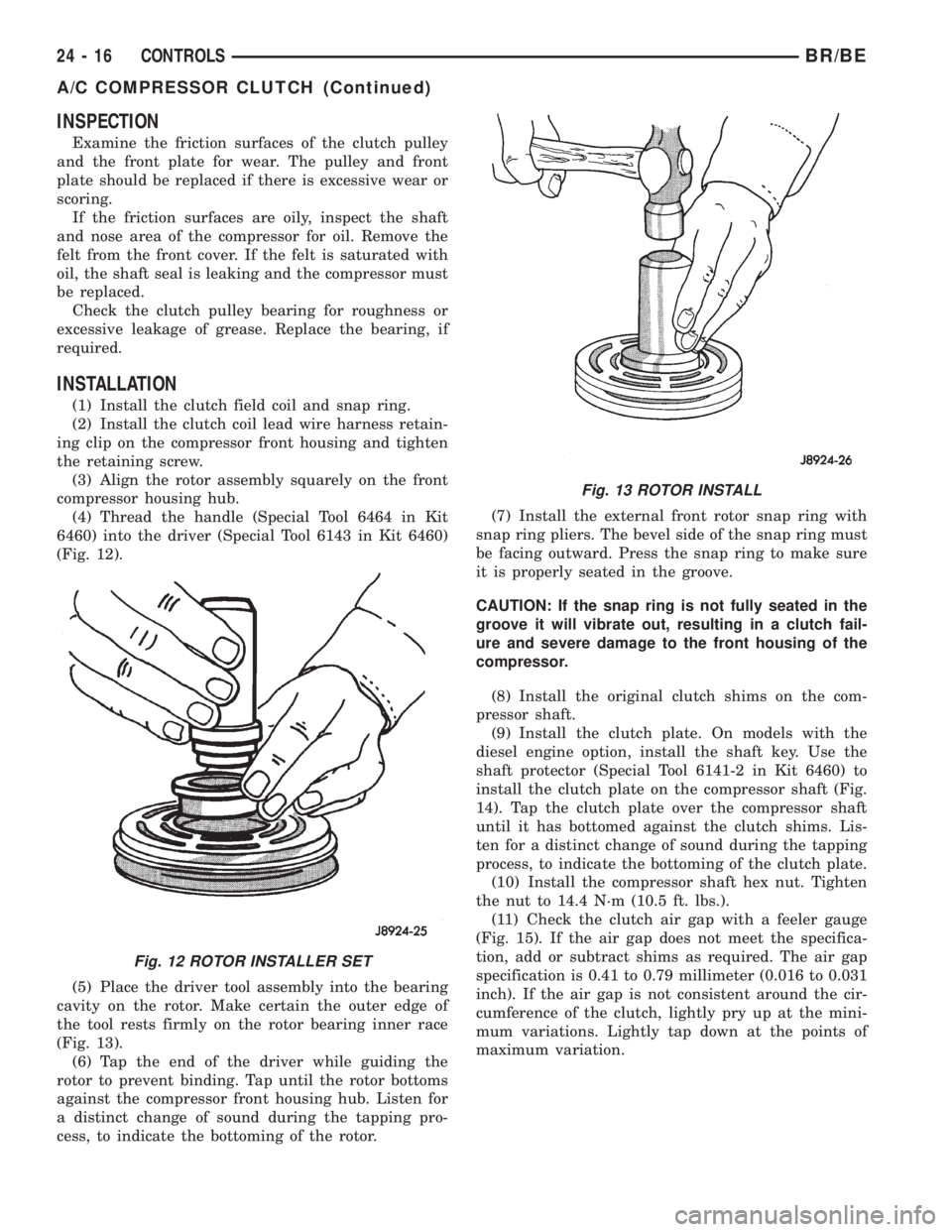
(4) Thread the handle (Special Tool 6464 in Kit
6460) into the driver (Special Tool 6143 in Kit 6460)
(Fig. 12).
(5) Place the driver tool assembly into the bearing
cavity on the rotor. Make certain the outer edge of
the tool rests firmly on the rotor bearing inner race
(Fig. 13).
(6) Tap the end of the driver while guiding the
rotor to prevent binding. Tap until the rotor bottoms
against the compressor front housing hub. Listen for
a distinct change of sound during the tapping pro-
cess, to indicate the bottoming of the rotor.(7) Install the external front rotor snap ring with
snap ring pliers. The bevel side of the snap ring must
be facing outward. Press the snap ring to make sure
it is properly seated in the groove.
CAUTION: If the snap ring is not fully seated in the
groove it will vibrate out, resulting in a clutch fail-
ure and severe damage to the front housing of the
compressor.
(8) Install the original clutch shims on the com-
pressor shaft.
(9) Install the clutch plate. On models with the
diesel engine option, install the shaft key. Use the
shaft protector (Special Tool 6141-2 in Kit 6460) to
install the clutch plate on the compressor shaft (Fig.
14). Tap the clutch plate over the compressor shaft
until it has bottomed against the clutch shims. Lis-
ten for a distinct change of sound during the tapping
process, to indicate the bottoming of the clutch plate.
(10) Install the compressor shaft hex nut. Tighten
the nut to 14.4 N´m (10.5 ft. lbs.).
(11) Check the clutch air gap with a feeler gauge
(Fig. 15). If the air gap does not meet the specifica-
tion, add or subtract shims as required. The air gap
specification is 0.41 to 0.79 millimeter (0.016 to 0.031
inch). If the air gap is not consistent around the cir-
cumference of the clutch, lightly pry up at the mini-
mum variations. Lightly tap down at the points of
maximum variation.
Fig. 12 ROTOR INSTALLER SET
Fig. 13 ROTOR INSTALL
24 - 16 CONTROLSBR/BE
A/C COMPRESSOR CLUTCH (Continued)