2001 DODGE RAM check engine light
[x] Cancel search: check engine lightPage 1412 of 2889
(11) Check the bore cleanliness by wiping with a
white, lint free, lightly oiled cloth. If grit residue is
still present, repeat the cleaning process until all res-
idue is removed. Wash the bores and the complete
block assembly with solvent and dry with compressed
air.
(12) Be sure to remove the tape covering the lube
holes after the cleaning process is complete.
STANDARD PROCEDUREÐCYLINDER BORE
REPAIR
Cylinder bore(s) can be repaired by one of two
methods:
²Method 1:ÐOver boring and using oversize pis-
tons and rings.
²Method 2:ÐBoring and installing a repair sleeve
to return the bore to standard dimensions.
METHOD 1ÐOVERSIZE BORE
Cylinder bore(s) can be repaired by one of two
methods:
Oversize pistons and rings are available in two
sizes - 0.50 mm (0.0197 inch) and 1.00 mm (0.0393
inch).
Any combination of standard, 0.50 mm (0.0197
inch) or 1.00 mm (0.0393 inch) overbore may be used
in the same engine.
If more than 1.00 mm (0.0393 inch) overbore is
needed, a repair sleeve can be installed (refer to
Method 2ÐRepair Sleeve).
Cylinder block bores may be bored twice before use
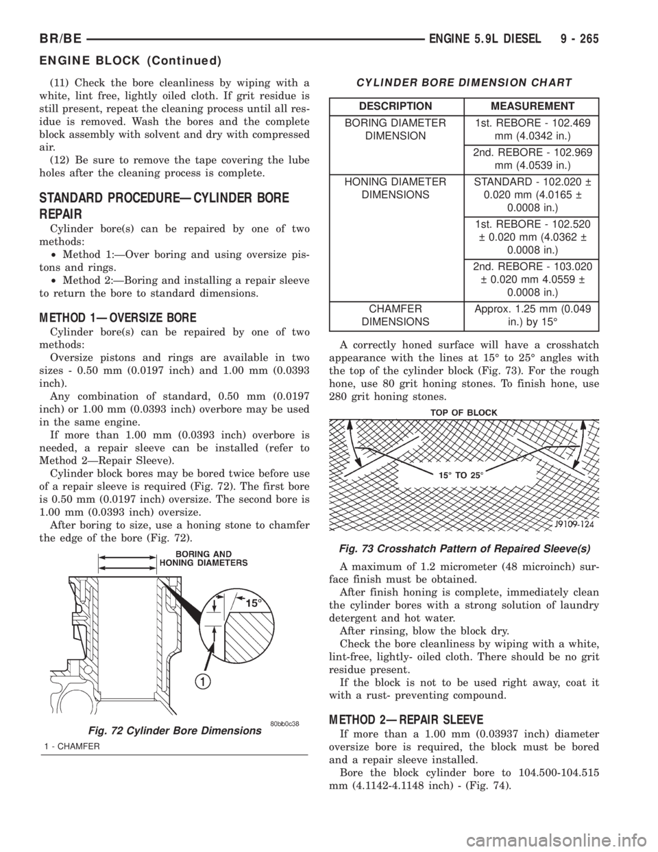
of a repair sleeve is required (Fig. 72). The first bore
is 0.50 mm (0.0197 inch) oversize. The second bore is
1.00 mm (0.0393 inch) oversize.
After boring to size, use a honing stone to chamfer
the edge of the bore (Fig. 72).
CYLINDER BORE DIMENSION CHART
DESCRIPTION MEASUREMENT
BORING DIAMETER
DIMENSION1st. REBORE - 102.469
mm (4.0342 in.)
2nd. REBORE - 102.969
mm (4.0539 in.)
HONING DIAMETER
DIMENSIONSSTANDARD - 102.020
0.020 mm (4.0165
0.0008 in.)
1st. REBORE - 102.520
0.020 mm (4.0362
0.0008 in.)
2nd. REBORE - 103.020
0.020 mm 4.0559
0.0008 in.)
CHAMFER
DIMENSIONSApprox. 1.25 mm (0.049
in.) by 15É
A correctly honed surface will have a crosshatch
appearance with the lines at 15É to 25É angles with
the top of the cylinder block (Fig. 73). For the rough
hone, use 80 grit honing stones. To finish hone, use
280 grit honing stones.
A maximum of 1.2 micrometer (48 microinch) sur-
face finish must be obtained.
After finish honing is complete, immediately clean
the cylinder bores with a strong solution of laundry
detergent and hot water.
After rinsing, blow the block dry.
Check the bore cleanliness by wiping with a white,
lint-free, lightly- oiled cloth. There should be no grit
residue present.
If the block is not to be used right away, coat it
with a rust- preventing compound.
METHOD 2ÐREPAIR SLEEVE
If more than a 1.00 mm (0.03937 inch) diameter
oversize bore is required, the block must be bored
and a repair sleeve installed.
Bore the block cylinder bore to 104.500-104.515
mm (4.1142-4.1148 inch) - (Fig. 74).Fig. 72 Cylinder Bore Dimensions
1 - CHAMFER
Fig. 73 Crosshatch Pattern of Repaired Sleeve(s)
BR/BEENGINE 5.9L DIESEL 9 - 265
ENGINE BLOCK (Continued)
Page 1443 of 2889
²Milky discoloration indicates coolant dilution.
(4) Clean the area around the oil filter head.
Remove the filter (Refer to 9 - ENGINE/LUBRICA-
TION/OIL FILTER - REMOVAL).
(5) Install new oil filter (Refer to 9 - ENGINE/LU-
BRICATION/OIL FILTER - INSTALLATION).
(6) Clean the drain plug and the sealing surface of
the pan. Check the condition of the threads and seal-
ing surface on the oil pan and drain plug.
(7) Install the drain plug. Tighten the plug to 60
N´m (44 ft. lbs.) torque.
(8) Use only High-Quality Multi-Viscosity lubricat-
ing oil in the Cummins Turbo Diesel engine. Choose
the correct oil for the operating conditions (Refer to
LUBRICATION & MAINTENANCE/FLUID TYPES -
DESCRIPTION).
(9) Fill the engine with the correct grade of new oil
(Refer to LUBRICATION & MAINTENANCE/FLUID
CAPACITIES - SPECIFICATIONS).
(10) Start the engine and operate it at idle for sev-
eral minutes. Check for leaks at the filter and drain
plug.
(11) Stop engine. Wait several minutes to allow the
oil to drain back to the pan and check the level
again.
USED ENGINE OIL DISPOSAL Care should be
exercised when disposing of used engine oil after
it has been drained from a vehicle's engine.
OIL COOLER & LINES
CLEANING AND INSPECTION
Clean the sealing surfaces.
Apply 483 kPa (70 psi) air pressure to the element
to check for leaks. If the element leaks, replace the
element.
OIL FILTER
REMOVAL
(1) Clean the area around the oil filter head.
Remove the filter using a 90-95 mm filter wrench.
(2) Clean the gasket surface of the filter head. The
filter canister O-Ring seal can stick on the filter
head. Make sure it is removed.
INSTALLATION
(1) Fill the oil filter element with clean oil before
installation. Use the same type oil that will be used
in the engine.
(2) Apply a light film of lubricating oil to the seal-
ing surface before installing the filter.CAUTION: Mechanical over-tightening may distort
the threads or damage the filter element seal.
(3) Install the filter until it contacts the sealing
surface of the oil filter adapter. Tighten filter an
additional ó turn.
OIL PAN
REMOVAL
(1) Disconnect the battery negative cables.
(2) Raise vehicle on hoist.
(3) Remove transmission and transfer case (if
equipped).
(4) Remove flywheel.
(5) Disconnect starter cables from starter motor.
(6) Remove starter motor (Refer to 8 - ELECTRI-
CAL/STARTING/STARTER MOTOR - REMOVAL)
and transmission adapter plate assembly.
WARNING: HOT OIL CAN CAUSE PERSONAL
INJURY.
(7) Drain the engine oil (Refer to 9 - ENGINE/LU-
BRICATION/OIL - STANDARD PROCEDURE).
(8) Install the oil pan drain plug with a new seal-
ing washer and tighten to 60 N´m (44 ft. lbs.) torque.
(9) Remove oil pan bolts, break the pan to block
seal, and lower pan slightly and remove oil suction
tube fasteners.
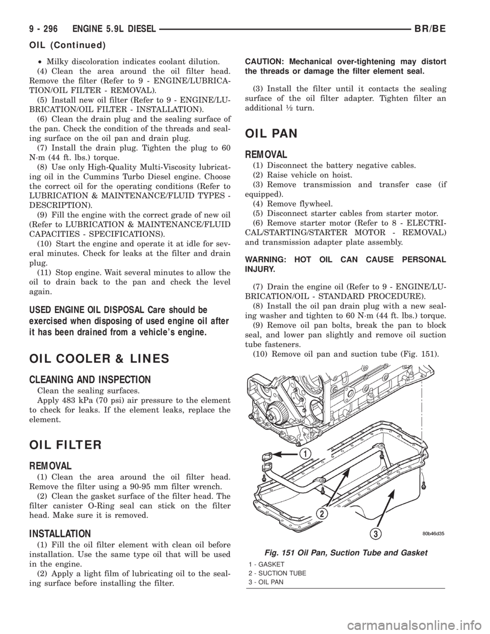
(10) Remove oil pan and suction tube (Fig. 151).
Fig. 151 Oil Pan, Suction Tube and Gasket
1 - GASKET
2 - SUCTION TUBE
3 - OIL PAN
9 - 296 ENGINE 5.9L DIESELBR/BE
OIL (Continued)
Page 1505 of 2889
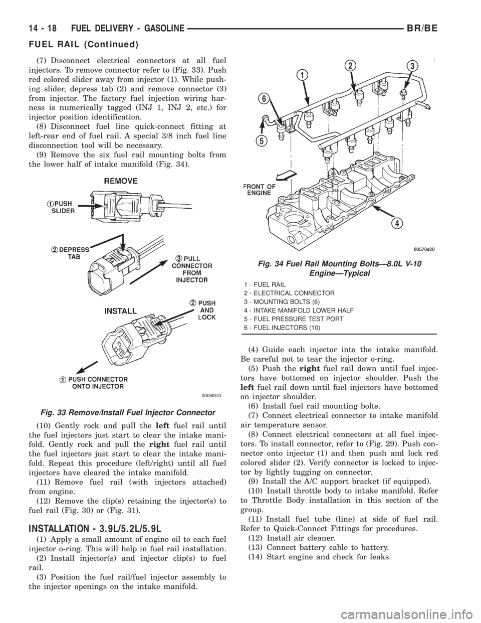
(7) Disconnect electrical connectors at all fuel
injectors. To remove connector refer to (Fig. 33). Push
red colored slider away from injector (1). While push-
ing slider, depress tab (2) and remove connector (3)
from injector. The factory fuel injection wiring har-
ness is numerically tagged (INJ 1, INJ 2, etc.) for
injector position identification.
(8) Disconnect fuel line quick-connect fitting at
left-rear end of fuel rail. A special 3/8 inch fuel line
disconnection tool will be necessary.
(9) Remove the six fuel rail mounting bolts from
the lower half of intake manifold (Fig. 34).
(10) Gently rock and pull theleftfuel rail until
the fuel injectors just start to clear the intake mani-
fold. Gently rock and pull therightfuel rail until
the fuel injectors just start to clear the intake mani-
fold. Repeat this procedure (left/right) until all fuel
injectors have cleared the intake manifold.
(11) Remove fuel rail (with injectors attached)
from engine.
(12) Remove the clip(s) retaining the injector(s) to
fuel rail (Fig. 30) or (Fig. 31).
INSTALLATION - 3.9L/5.2L/5.9L
(1) Apply a small amount of engine oil to each fuel
injector o-ring. This will help in fuel rail installation.
(2) Install injector(s) and injector clip(s) to fuel
rail.
(3) Position the fuel rail/fuel injector assembly to
the injector openings on the intake manifold.(4) Guide each injector into the intake manifold.
Be careful not to tear the injector o-ring.
(5) Push therightfuel rail down until fuel injec-
tors have bottomed on injector shoulder. Push the
leftfuel rail down until fuel injectors have bottomed
on injector shoulder.
(6) Install fuel rail mounting bolts.
(7) Connect electrical connector to intake manifold
air temperature sensor.
(8) Connect electrical connectors at all fuel injec-
tors. To install connector, refer to (Fig. 29). Push con-
nector onto injector (1) and then push and lock red
colored slider (2). Verify connector is locked to injec-
tor by lightly tugging on connector.
(9) Install the A/C support bracket (if equipped).
(10) Install throttle body to intake manifold. Refer
to Throttle Body installation in this section of the
group.
(11) Install fuel tube (line) at side of fuel rail.
Refer to Quick-Connect Fittings for procedures.
(12) Install air cleaner.
(13) Connect battery cable to battery.
(14) Start engine and check for leaks.
Fig. 33 Remove/Install Fuel Injector Connector
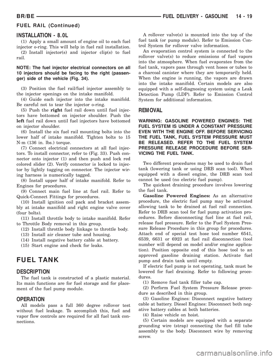
Fig. 34 Fuel Rail Mounting BoltsÐ8.0L V-10
EngineÐTypical
1 - FUEL RAIL
2 - ELECTRICAL CONNECTOR
3 - MOUNTING BOLTS (6)
4 - INTAKE MANIFOLD LOWER HALF
5 - FUEL PRESSURE TEST PORT
6 - FUEL INJECTORS (10)
14 - 18 FUEL DELIVERY - GASOLINEBR/BE
FUEL RAIL (Continued)
Page 1506 of 2889
INSTALLATION - 8.0L
(1) Apply a small amount of engine oil to each fuel
injector o-ring. This will help in fuel rail installation.
(2) Install injector(s) and injector clip(s) to fuel
rail.
NOTE: The fuel injector electrical connectors on all
10 injectors should be facing to the right (passen-
ger) side of the vehicle (Fig. 34).
(3) Position the fuel rail/fuel injector assembly to
the injector openings on the intake manifold.
(4) Guide each injector into the intake manifold.
Be careful not to tear the injector o-ring.
(5) Push therightfuel rail down until fuel injec-
tors have bottomed on injector shoulder. Push the
leftfuel rail down until fuel injectors have bottomed
on injector shoulder.
(6) Install the six fuel rail mounting bolts into the
lower half of intake manifold. Tighten bolts to 15
N´m (136 in. lbs.) torque.
(7) Connect electrical connectors at all fuel injec-
tors. To install connector, refer to (Fig. 33). Push con-
nector onto injector (1) and then push and lock red
colored slider (2). Verify connector is locked to injec-
tor by lightly tugging on connector. The injector wir-
ing harness is numerically tagged.
(8) Install upper half of intake manifold. Refer to
Engines for procedures.
(9) Connect main fuel line at fuel rail. Refer to
Quick-Connect Fittings for procedures.
(10) Install ignition coil pack and bracket assem-
bly at intake manifold and right engine valve cover
(four bolts).
(11) Install throttle body to intake manifold. Refer
to Throttle Body removal in this group.
(12) Install throttle body linkage to throttle body.
(13) Install air cleaner tube and housing.
(14) Install negative battery cable at battery.
(15) Start engine and check for leaks.
FUEL TANK
DESCRIPTION
The fuel tank is constructed of a plastic material.
Its main functions are for fuel storage and for place-
ment of the fuel pump module.
OPERATION
All models pass a full 360 degree rollover test
without fuel leakage. To accomplish this, fuel and
vapor flow controls are required for all fuel tank con-
nections.A rollover valve(s) is mounted into the top of the
fuel tank (or pump module). Refer to Emission Con-
trol System for rollover valve information.
An evaporation control system is connected to the
rollover valve(s) to reduce emissions of fuel vapors
into the atmosphere. When fuel evaporates from the
fuel tank, vapors pass through vent hoses or tubes to
a charcoal canister where they are temporarily held.
When the engine is running, the vapors are drawn
into the intake manifold. Certain models are also
equipped with a self-diagnosing system using a Leak
Detection Pump (LDP). Refer to Emission Control
System for additional information.
REMOVAL
WARNING: GASOLINE POWERED ENGINES: THE
FUEL SYSTEM IS UNDER A CONSTANT PRESSURE
EVEN WITH THE ENGINE OFF. BEFORE SERVICING
THE FUEL TANK, FUEL SYSTEM PRESSURE MUST
BE RELEASED. REFER TO THE FUEL SYSTEM
PRESSURE RELEASE PROCEDURE BEFORE SER-
VICING THE FUEL TANK.
Two different procedures may be used to drain fuel
tank (lowering tank or using DRB scan tool). When
equipped with a diesel engine, the DRB scan tool
cannot be used (no electric fuel pump).
The quickest draining procedure involves lowering
the fuel tank.
Gasoline Powered Engines:As an alternative
procedure, the electric fuel pump may be activated
allowing tank to be drained at fuel rail connection.
Refer to DRB scan tool for fuel pump activation pro-
cedures. Before disconnecting fuel line at fuel rail,
release fuel pressure. Refer to the Fuel System Pres-
sure Release Procedure in this group for procedures.
Attach end of special test hose tool number 6541,
6539, 6631 or 6923 at fuel rail disconnection (tool
number will depend on model and/or engine applica-
tion). Position opposite end of this hose tool to an
approved gasoline draining station. Activate fuel
pump and drain tank until empty.
If electric fuel pump is not operating, tank must be
lowered for fuel draining. Refer to following proce-
dures.
(1) Remove fuel tank filler tube cap.
(2) Perform Fuel System Pressure Release proce-
dure as described in this group.
(3) Gasoline Engines: Disconnect negative battery
cable at battery. Diesel Engines: Disconnect both neg-
ative battery cables at both batteries.
(4) Raise vehicle on hoist.
(5) Certain models are equipped with a separate
grounding wire (strap) connecting the fuel fill tube
assembly to the body. Disconnect wire by removing
screw.
BR/BEFUEL DELIVERY - GASOLINE 14 - 19
FUEL RAIL (Continued)
Page 1527 of 2889

REMOVAL - 8.0L
The crankshaft position sensor is located on the
right-lower side of the cylinder block, forward of the
right engine mount, just above the oil pan rail (Fig.
28).
(1) Raise and support vehicle.
(2) Disconnect sensor pigtail harness from main
engine wiring harness.
(3) Remove sensor mounting bolt (Fig. 29).
(4) Cut plastic tie strap (Fig. 28) securing sensor
pigtail harness to side of engine block.
(5) Carefully pry sensor from cylinder block in a
rocking action with two small screwdrivers.
(6) Remove sensor from vehicle.
(7) Check condition of sensor o-ring (Fig. 30).
INSTALLATION - 3.9L/5.2L/5.9L
(1) Position crankshaft position sensor to engine.
(2) Install mounting bolts and tighten to 8 N´m (70
in. lbs.) torque.
(3) Connect main harness electrical connector to
sensor.
(4) Install air cleaner tube.
INSTALLATION - 8.0L
The crankshaft position sensor is located on the
right-lower side of the cylinder block, forward of the
right engine mount, just above the oil pan rail (Fig.
28).(1) Apply a small amount of engine oil to sensor
o-ring (Fig. 30).
(2) Install sensor into cylinder block with a slight
rocking action. Do not twist sensor into position as
damage to o-ring may result.
CAUTION: Before tightening sensor mounting bolt,
be sure sensor is completely flush to cylinder block
(Fig. 29). If sensor is not flush, damage to sensor
mounting tang may result.
(3) Install mounting bolt and tighten to 8 N´m (70
in. lbs.) torque.
(4) Connect sensor pigtail harness to main engine
wiring harness
Fig. 28 Crankshaft Position Sensor LocationÐ8.0L
V-10 Engine
1 - CRANKSHAFT POSITION SENSOR
2 - HOLE
3 - OIL FILTER
4 - PLASTIC TIE STRAP
5 - PIGTAIL HARNESS
Fig. 29 Sensor Removal/InstallationÐ8.0L V-10
Engine
1 - CRANKSHAFT POSITION SENSOR
2 - MOUNTING BOLT
3 - SENSOR POSITIONED FLUSH TO CYLINDER BLOCK
Fig. 30 Sensor O-RingÐ8.0L V-10 Engine
1 - CRANKSHAFT POSITION SENSOR O-RING
2 - ELECTRICAL CONNECTOR
3 - PIGTAIL HARNESS
14 - 40 FUEL INJECTION - GASOLINEBR/BE
CRANKSHAFT POSITION SENSOR (Continued)
Page 1533 of 2889
(3) Install MAP sensor mounting bolts (screws).
Tighten screws to 3 N´m (25 in. lbs.) torque.
(4) Install air cleaner.
INSTALLATION - 8.0L
The MAP sensor is mounted into the right upper
side of the intake manifold (Fig. 38). A rubber gasket
is used to seal the sensor to the intake manifold. The
rubber gasket is part of the sensor and is not ser-
viced separately.
(1) Check the condition of the sensor seal. Clean
the sensor and lubricate the rubber gasket with clean
engine oil.
(2) Clean the sensor opening in the intake mani-
fold.
(3) Install the sensor into the intake manifold.
(4) Install sensor mounting bolts. Tighten bolts to
2 N´m (20 in. lbs.) torque.
(5) Install the electrical connector to sensor.
O2 SENSOR
DESCRIPTION
The Oxygen Sensors (O2S) are attached to, and
protrude into the vehicle exhaust system. Depending
on the emission package, the vehicle may use a total
of either 2 or 4 sensors.
3.9L/5.2L/Light Duty 5.9L Engine:Four sensors
are used: 2 upstream (referred to as 1/1 and 2/1) and
2 downstream (referred to as 1/2 and 2/2). With this
emission package, the right upstream sensor (2/1) is
located in the right exhaust downpipe just before the
mini-catalytic convertor. The left upstream sensor
(1/1) is located in the left exhaust downpipe just
before the mini-catalytic convertor. The right down-
stream sensor (2/2) is located in the right exhaust
downpipe just after the mini-catalytic convertor, and
before the main catalytic convertor. The left down-
stream sensor (1/2) is located in the left exhaust
downpipe just after the mini-catalytic convertor, and
before the main catalytic convertor.
Medium and Heavy Duty 8.0L V-10 Engine:
Four sensors are used (2 upstream, 1 pre-catalyst
and 1 post-catalyst). With this emission package, the
1/1 upstream sensor (left side) is located in the left
exhaust downpipe before both the pre-catalyst sensor
(1/2), and the main catalytic convertor. The 2/1
upstream sensor (right side) is located in the right
exhaust downpipe before both the pre-catalyst sensor
(1/2), and the main catalytic convertor. The pre-cata-
lyst sensor (1/2) is located after the 1/1 and 2/1 sen-
sors, and just before the main catalytic convertor.
The post-catalyst sensor (1/3) is located just after the
main catalytic convertor.Heavy Duty 5.9L Engine:Two sensors are used.
They arebothreferred to as upstream sensors (left
side is referred to as 1/1 and right side is referred to
as 2/1). With this emission package, a sensor is
located in each of the exhaust downpipes before the
main catalytic convertor.
OPERATION
An O2 sensor is a galvanic battery that provides
the PCM with a voltage signal (0-1 volt) inversely
proportional to the amount of oxygen in the exhaust.
In other words, if the oxygen content is low, the volt-
age output is high; if the oxygen content is high the
output voltage is low. The PCM uses this information
to adjust injector pulse-width to achieve the
14.7±to±1 air/fuel ratio necessary for proper engine
operation and to control emissions.
The O2 sensor must have a source of oxygen from
outside of the exhaust stream for comparison. Cur-
rent O2 sensors receive their fresh oxygen (outside
air) supply through the wire harness. This is why it
is important to never solder an O2 sensor connector,
or pack the connector with grease.
Four wires (circuits) are used on each O2 sensor: a
12±volt feed circuit for the sensor heating element; a
ground circuit for the heater element; a low-noise
sensor return circuit to the PCM, and an input cir-
cuit from the sensor back to the PCM to detect sen-
sor operation.
Oxygen Sensor Heaters/Heater Relays:
Depending on the emissions package, the heating ele-
ments within the sensors will be supplied voltage
from either the ASD relay, or 2 separate oxygen sen-
sor relays. Refer to 8, Wiring Diagrams to determine
which relays are used.
The O2 sensor uses a Positive Thermal Co-efficient
(PTC) heater element. As temperature increases,
resistance increases. At ambient temperatures
around 70ÉF, the resistance of the heating element is
approximately 4.5 ohms. As the sensor's temperature
increases, resistance in the heater element increases.
This allows the heater to maintain the optimum
operating temperature of approximately 930É-1100ÉF
(500É-600É C). Although the sensors operate the
same, there are physical differences, due to the envi-
ronment that they operate in, that keep them from
being interchangeable.
Maintaining correct sensor temperature at all times
allows the system to enter into closed loop operation
sooner. Also, it allows the system to remain in closed
loop operation during periods of extended idle.
In Closed Loop operation, the PCM monitors cer-
tain O2 sensor input(s) along with other inputs, and
adjusts the injector pulse width accordingly. During
Open Loop operation, the PCM ignores the O2 sensor
input. The PCM adjusts injector pulse width based
14 - 46 FUEL INJECTION - GASOLINEBR/BE
MANIFOLD ABSOLUTE PRESSURE SENSOR (Continued)
Page 1539 of 2889
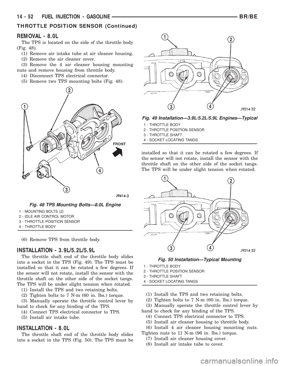
REMOVAL - 8.0L
The TPS is located on the side of the throttle body
(Fig. 48).
(1) Remove air intake tube at air cleaner housing.
(2) Remove the air cleaner cover.
(3) Remove the 4 air cleaner housing mounting
nuts and remove housing from throttle body.
(4) Disconnect TPS electrical connector.
(5) Remove two TPS mounting bolts (Fig. 48).
(6) Remove TPS from throttle body.
INSTALLATION - 3.9L/5.2L/5.9L
The throttle shaft end of the throttle body slides
into a socket in the TPS (Fig. 49). The TPS must be
installed so that it can be rotated a few degrees. If
the sensor will not rotate, install the sensor with the
throttle shaft on the other side of the socket tangs.
The TPS will be under slight tension when rotated.
(1) Install the TPS and two retaining bolts.
(2) Tighten bolts to 7 N´m (60 in. lbs.) torque.
(3) Manually operate the throttle control lever by
hand to check for any binding of the TPS.
(4) Connect TPS electrical connector to TPS.
(5) Install air intake tube.
INSTALLATION - 8.0L
The throttle shaft end of the throttle body slides
into a socket in the TPS (Fig. 50). The TPS must beinstalled so that it can be rotated a few degrees. If
the sensor will not rotate, install the sensor with the
throttle shaft on the other side of the socket tangs.
The TPS will be under slight tension when rotated.
(1) Install the TPS and two retaining bolts.
(2) Tighten bolts to 7 N´m (60 in. lbs.) torque.
(3) Manually operate the throttle control lever by
hand to check for any binding of the TPS.
(4) Connect TPS electrical connector to TPS.
(5) Install air cleaner housing to throttle body.
(6) Install 4 air cleaner housing mounting nuts.
Tighten nuts to 11 N´m (96 in. lbs.) torque.
(7) Install air cleaner housing cover.
(8) Install air intake tube to cover.
Fig. 48 TPS Mounting BoltsÐ8.0L Engine
1 - MOUNTING BOLTS (2)
2 - IDLE AIR CONTROL MOTOR
3 - THROTTLE POSITION SENSOR
4 - THROTTLE BODY
Fig. 49 InstallationÐ3.9L/5.2L/5.9L EnginesÐTypical
1 - THROTTLE BODY
2 - THROTTLE POSITION SENSOR
3 - THROTTLE SHAFT
4 - SOCKET LOCATING TANGS
Fig. 50 InstallationÐTypical Mounting
1 - THROTTLE BODY
2 - THROTTLE POSITION SENSOR
3 - THROTTLE SHAFT
4 - SOCKET LOCATING TANGS
14 - 52 FUEL INJECTION - GASOLINEBR/BE
THROTTLE POSITION SENSOR (Continued)
Page 1548 of 2889
(c) Check condition of o-ring.(d) Inspect the 2 WIF sensor probes. Carefully
clean contaminants from sensor probes with a cloth
if necessary. Replace sensor if probes are covered
with contaminants and will not clean up.
(7)Fuel Heater Element Replacement:The
heater element is located in the fuel filter housing
(Fig. 6).
(a) Remove fuel filter. See previous steps.
(b) Disconnect electrical connector from fuel tem-
perature sensor housing at side of fuel filter hous-
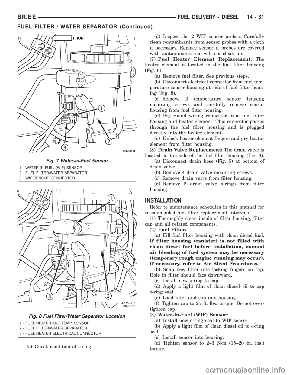
ing (Fig. 8).
(c) Remove 2 temperature sensor housing
mounting screws and carefully remove sensor
housing from fuel filter housing.
(d) Pry round wiring connector from fuel filter
housing and heater element. This connector passes
through the fuel filter housing and is plugged
directly into the heater element.
(e) Unlock heater element fingers and pry heater
element from filter housing.
(8)Drain Valve Replacement:The drain valve is
located on the side of the fuel filter housing (Fig. 6).
(a) Disconnect drain hose (Fig. 5) at bottom of
drain valve.
(b) Remove 4 drain valve mounting screws.
(c) Remove drain valve from filter housing.
(d) Remove 2 drain valve o-rings from filter
housing.
INSTALLATION
Refer to maintenance schedules in this manual for
recommended fuel filter replacement intervals.
(1) Thoroughly clean inside of filter housing, filter
cap and all related components.
(2)Fuel Filter:
(a) Fill fuel filter housing with clean diesel fuel.
If filter housing (canister) is not filled with
clean diesel fuel before installation, manual
air bleeding of fuel system may be necessary
(temporary rough engine running may occur).
If necessary, refer to Air Bleed Procedures.
(b) Snap new filter into locking fingers on cap.
Hole in filter should face downward.
(c) Install new o-ring to cap.
(d) Apply a light film of clean diesel oil to cap
o-ring seal.
(e) Load filter and cap into housing.
(f) Tighten cap to 25 ft. lbs. torque. Do not over-
tighten cap.
(3)Water-In-Fuel (WIF) Sensor:
(a) Install new o-ring seal to WIF sensor.
(b) Apply a light film of clean diesel oil to o-ring
seal.
(c) Install sensor into housing.
(d) Tighten sensor to 2±3 N´m (15±20 in. lbs.)
torque.
Fig. 7 Water-In-Fuel Sensor
1 - WATER-IN-FUEL (WIF) SENSOR
2 - FUEL FILTER/WATER SEPARATOR
3 - WIF SENSOR CONNECTOR
Fig. 8 Fuel Filter/Water Separator Location
1 - FUEL HEATER AND TEMP. SENSOR
2 - FUEL FILTER/WATER SEPARATOR
3 - FUEL HEATER ELECTRICAL CONNECTOR
BR/BEFUEL DELIVERY - DIESEL 14 - 61
FUEL FILTER / WATER SEPARATOR (Continued)