2001 DODGE RAM check engine light
[x] Cancel search: check engine lightPage 1549 of 2889
(e) Connect electrical connector to WIF sensor.
(f) Install fuel filter. Refer to previous steps.
(4)Fuel Heater Element:
(a) Do not install fuel filter until heater element
is installed.
(b) Position heater element into filter housing
(fingers downward). Lock fingers into housing.
(c) Install new o-ring to electrical connector
(where connector passes through filter housing).
Apply a light film of clean diesel oil to o-ring seal.
Press this connector into filter housing until it
snaps into heater element.
(d) Install temperature sensor housing and 2
mounting screws to fuel filter housing.
(e) Connect electrical connector.
(f) Install fuel filter. Refer to previous steps.
(5)Drain Valve:
(a) Install 2 new o-rings to valve and filter hous-
ing.
(b) Apply a light film of clean diesel oil to both
seals.
(c) Position valve to filter housing.
(d) Install 4 mounting screws and tighten to 3±5
N´m (30±40 in. lbs.) torque.
(e) Connect drain hose to drain valve.
(f) Install fuel filter. Refer to previous steps.
(6) Start engine and check for leaks.
FUEL HEATER
DESCRIPTION
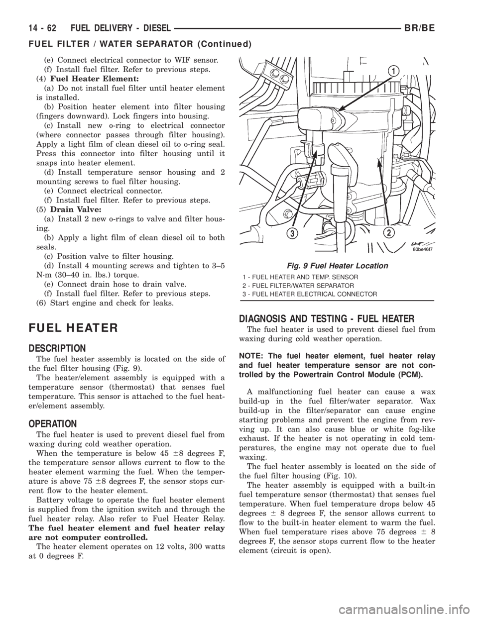
The fuel heater assembly is located on the side of
the fuel filter housing (Fig. 9).
The heater/element assembly is equipped with a
temperature sensor (thermostat) that senses fuel
temperature. This sensor is attached to the fuel heat-
er/element assembly.
OPERATION
The fuel heater is used to prevent diesel fuel from
waxing during cold weather operation.
When the temperature is below 4568 degrees F,
the temperature sensor allows current to flow to the
heater element warming the fuel. When the temper-
ature is above 7568 degrees F, the sensor stops cur-
rent flow to the heater element.
Battery voltage to operate the fuel heater element
is supplied from the ignition switch and through the
fuel heater relay. Also refer to Fuel Heater Relay.
The fuel heater element and fuel heater relay
are not computer controlled.
The heater element operates on 12 volts, 300 watts
at 0 degrees F.
DIAGNOSIS AND TESTING - FUEL HEATER
The fuel heater is used to prevent diesel fuel from
waxing during cold weather operation.
NOTE: The fuel heater element, fuel heater relay
and fuel heater temperature sensor are not con-
trolled by the Powertrain Control Module (PCM).
A malfunctioning fuel heater can cause a wax
build-up in the fuel filter/water separator. Wax
build-up in the filter/separator can cause engine
starting problems and prevent the engine from rev-
ving up. It can also cause blue or white fog-like
exhaust. If the heater is not operating in cold tem-
peratures, the engine may not operate due to fuel
waxing.
The fuel heater assembly is located on the side of
the fuel filter housing (Fig. 10).
The heater assembly is equipped with a built-in
fuel temperature sensor (thermostat) that senses fuel
temperature. When fuel temperature drops below 45
degrees68 degrees F, the sensor allows current to
flow to the built-in heater element to warm the fuel.
When fuel temperature rises above 75 degrees68
degrees F, the sensor stops current flow to the heater
element (circuit is open).
Fig. 9 Fuel Heater Location
1 - FUEL HEATER AND TEMP. SENSOR
2 - FUEL FILTER/WATER SEPARATOR
3 - FUEL HEATER ELECTRICAL CONNECTOR
14 - 62 FUEL DELIVERY - DIESELBR/BE
FUEL FILTER / WATER SEPARATOR (Continued)
Page 1638 of 2889
The driver selects a particular gear by moving the
shift lever to the desired gear position. This move-
ment moves the internal transmission shift compo-
nents to begin the shift sequence. As the shift lever
moves the selected shift rail, the shift fork attached
to that rail begins to move. The fork is positioned in
a groove in the outer circumference of the synchro-
nizer sleeve. As the shift fork moves the synchronizer
sleeve, the synchronizer begins to speed-up or slow
down the selected gear (depending on whether we are
up-shifting or down-shifting). The synchronizer does
this by having the synchronizer hub splined to the
mainshaft, or the countershaft in some cases, and
moving the blocker ring into contact with the gear's
friction cone. As the blocker ring and friction cone
come together, the gear speed is brought up or down
to the speed of the synchronizer. As the two speeds
match, the splines on the inside of the synchronizer
sleeve become aligned with the teeth on the blocker
ring and the friction cone and eventually will slide
over the teeth, locking the gear to the mainshaft, or
countershaft, through the synchronizer.
DIAGNOSIS AND TESTING - MANUAL
TRANSMISSION
LOW LUBRICANT LEVEL
A low transmission lubricant level is generally the
result of a leak, inadequate lubricant fill or an incor-
rect lubricant level check.
Leaks can occur at the mating surfaces of the gear
case, adaptor or extension housing, or from the front/
rear seals. A suspected leak could also be the result
of an overfill condition.
Leaks at the rear of the extension or adapter hous-
ing will be from the housing oil seals. Leaks at com-
ponent mating surfaces will probably be the result of
inadequate sealer, gaps in the sealer, incorrect bolt
tightening or use of a non-recommended sealer.
A leak at the front of the transmission will be from
either the front bearing retainer or retainer seal.
Lubricant may be seen dripping from the clutch
housing after extended operation. If the leak is
severe, it may also contaminate the clutch disc caus-
ing the disc to slip, grab and or chatter.
A correct lubricant level check can only be made
when the vehicle is level. Also allow the lubricant to
settle for a minute or so before checking. These rec-
ommendations will ensure an accurate check and
avoid an underfill or overfill condition. Always check
the lubricant level after any addition of fluid to avoid
an incorrect lubricant level condition.
HARD SHIFTING
Hard shifting is usually caused by a low lubricant
level, improper or contaminated lubricants. The con-sequence of using non-recommended lubricants is
noise, excessive wear, internal bind and hard shift-
ing. Substantial lubricant leaks can result in gear,
shift rail, synchro, and bearing damage. If a leak
goes undetected for an extended period, the first indi-
cations of component damage are usually hard shift-
ing and noise.
Component damage, incorrect clutch adjustment or
damaged clutch pressure plate or disc are additional
probable causes of increased shift effort. Incorrect
adjustment or a worn/damaged pressure plate or disc
can cause incorrect release. If clutch problem is
advanced, gear clash during shifts can result. Worn
or damaged synchro rings can cause gear clash when
shifting into any forward gear. In some new or
rebuilt transmissions, new synchro rings may tend to
stick slightly causing hard or noisy shifts. In most
cases this condition will decline as the rings wear-in.
TRANSMISSION NOISE
Most manual transmissions make some noise dur-
ing normal operation. Rotating gears generate a mild
whine that is audible, but generally only at extreme
speeds.
Severe highly audible transmission noise is gener-
ally the initial indicator of a lubricant problem.
Insufficient, improper or contaminated lubricant will
promote rapid wear of gears, synchros, shift rails,
forks and bearings. The overheating caused by a
lubricant problem, can also lead to gear breakage.
REMOVAL
(1) Disconnect battery negative cable.
(2) Shift transmission into Neutral.
(3) Remove shift boot bezel screws and slide boot
upward on shift lever extension.
(4) Remove shift lever extension from the shift
tower and lever assembly.
(5) Remove bolts attaching shift tower and lever
assembly to rear case. Then remove shift tower and
lever assembly.
(6) Raise vehicle on hoist.
(7) Remove crankshaft position sensor. Retain sen-
sor attaching bolts.
(8) Remove skid plate, if equipped.
(9) Drain transmission lubricant if transmission
will be disassembled for service.
(10) Mark propeller shaft/shafts and yoke/yokes for
installation reference and remove propeller shaft/
shafts.
(11) Disengage harness from clips on transmission
housing.
(12) Support engine with adjustable jack stand
and wood block.
(13) Drain transmission lubricant if transmission
will be disassembled for service.
BR/BEMANUAL - NV3500 21 - 3
MANUAL - NV3500 (Continued)
Page 1682 of 2889
A leak at the front of the transmission will be from
either the front bearing retainer or retainer seal.
Lubricant may be seen dripping from the clutch
housing after extended operation. If the leak is
severe, it may also contaminate the clutch disc caus-
ing the disc to slip, grab and or chatter.
A correct lubricant level check can only be made
when the vehicle is level. Also allow the lubricant to
settle for a minute or so before checking. These rec-
ommendations will ensure an accurate check and
avoid an underfill or overfill condition. Always check
the lubricant level after any addition of fluid to avoid
an incorrect lubricant level condition.
HARD SHIFTING
Hard shifting is usually caused by a low lubricant
level, improper or contaminated lubricants. The con-
sequence of using non-recommended lubricants is
noise, excessive wear, internal bind and hard shift-
ing. Substantial lubricant leaks can result in gear,
shift rail, synchro, and bearing damage. If a leak
goes undetected for an extended period, the first indi-
cations of component damage are usually hard shift-
ing and noise.
Component damage, incorrect clutch adjustment or
damaged clutch pressure plate or disc are additional
probable causes of increased shift effort. Incorrect
adjustment or a worn/damaged pressure plate or disc
can cause incorrect release. If clutch problem is
advanced, gear clash during shifts can result. Worn
or damaged synchro rings can cause gear clash when
shifting into any forward gear. In some new or
rebuilt transmissions, new synchro rings may tend to
stick slightly causing hard or noisy shifts. In most
cases this condition will decline as the rings wear-in.
TRANSMISSION NOISE
Most manual transmissions make some noise dur-
ing normal operation. Rotating gears generate a mild
whine that is audible, but generally only at extreme
speeds.
Severe highly audible transmission noise is gener-
ally the initial indicator of a lubricant problem.
Insufficient, improper or contaminated lubricant will
promote rapid wear of gears, synchros, shift rails,
forks and bearings. The overheating caused by a
lubricant problem, can also lead to gear breakage.
REMOVAL
(1) Disconnect battery negative cable.
(2) Shift transmission into Neutral.
(3) Remove shift boot screws from floorpan and
slide boot upward on the shift lever.
(4) Remove shift lever extension from shift tower
and lever assembly.(5) Remove shift tower bolts holding tower to iso-
lator plate and transmission shift cover.
(6) Remove shift tower and isolator plate from
transmission shift cover.
(7) Raise and support vehicle.
(8) Remove skid plate, if equipped.
(9) Mark propeller shaft and axle yokes for instal-
lation reference and remove shaft/shafts.
(10) Remove exhaust system Y-pipe.
(11) Disconnect speed sensor and backup light
switch connectors.
(12) Support engine with safety stand and a wood
block.
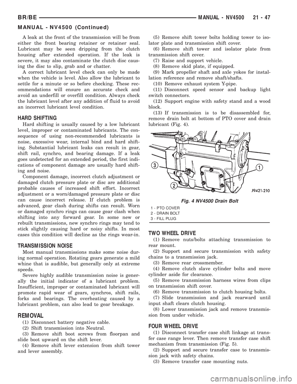
(13) If transmission is to be disassembled for,
remove drain bolt at bottom of PTO cover and drain
lubricant (Fig. 4).
TWO WHEEL DRIVE
(1) Remove nuts/bolts attaching transmission to
rear mount.
(2) Support and secure transmission with safety
chains to a transmission jack.
(3) Remove rear crossmember.
(4) Remove clutch slave cylinder bolts and move
cylinder aside for clearance.
(5) Remove transmission harness wires from clips
on transmission shift cover.
(6) Remove transmission to clutch housing bolts.
(7) Slide transmission and jack rearward until
input shaft clears clutch housing.
(8) Lower transmission jack and remove transmis-
sion from under vehicle.
FOUR WHEEL DRIVE
(1) Disconnect transfer case shift linkage at trans-
fer case range lever. Then remove transfer case shift
mechanism from transmission (Fig. 5).
(2) Support and secure transfer case to transmis-
sion jack with safety chains.
(3) Remove transfer case mounting nuts.
Fig. 4 NV4500 Drain Bolt
1 - PTO COVER
2 - DRAIN BOLT
3 - FILL PLUG
BR/BEMANUAL - NV4500 21 - 47
MANUAL - NV4500 (Continued)
Page 1717 of 2889
INSTALLATION
NOTE: If a new transmission is being installed, be
sure to use all components supplied with the new
transmission. For example, if a new shift tower is
supplied with the new transmission, do not re-use
the original shift tower.
Befor installation apply light coat of Mopar high
temperature bearing grease to contact surfaces of fol-
lowing components:
²input shaft splines.
²release bearing slide surface of front retainer.
²release bearing bore.
²release fork.
²release fork ball stud.
²propeller shaft slip yoke.
(1) Apply sealer to threads of bottom PTO cover
bolt and install bolt in case.
(2) Mount transmission on jack and position trans-
mission under vehicle.
(3) Raise transmission until input shaft is centered
in release bearing and clutch disc hub.
(4) Move transmission forward and start input
shaft in release bearing, clutch disc and pilot bush-
ing.
(5) Work transmission forward until seated against
clutch housing. Do not allow transmission to remain
unsupported after input shaft has entered clutch
disc.
(6) Install and tighten transmission-to-clutch hous-
ing bolts to 108 N´m (80 ft. lbs.).
(7) Install transmission mount on transmission or
rear crossmember.
(8) Install rear crossmember.
(9) Remove transmission jack and engine support
fixture.
(10) Position transmission harness wires in clips
on shift cover.
(11) Install clutch slave cylinder and install slave
cylinder shield, if equipped.
(12) Connect speed sensor and backup light switch
wires.
TWO WHEEL DRIVE
(1) Fill transmission with recommended lubricant.
Correct fill level is bottom edge of fill plug hole.
(2) Align and install propeller shaft.
(3) Lower vehicle.
(4) Clean the mating surfaces of shift tower, isola-
tor plate, and shift cover with suitable wax and
grease remover.
(5) Apply Mopar Gasket Maker, or equivalent, to
the sealing surface of the shift cover. Do not over
apply sealant.(6) Install the isolator plate onto the shift cover,
metal side down.
(7) Install the shift tower onto the isolator plate.
No sealant is necessary between the shift tower and
the isolator plate.
(8) Verify that the shift tower, isolator plate, and
the shift tower bushings are properly aligned.
(9) Install the bolts to hold the shift tower to the
isolator plate and the shift cover. Tighten the shift
tower bolts to 10.2±11.25 N´m (7.5±8.3 ft. lbs.).
(10) Install the shift lever extension onto the shift
tower and lever assembly.
(11) Install shift boot and bezel.
(12) Connect battery negative cable.
FOUR WHEEL DRIVE
(1) Install transfer case shift mechanism on trans-
mission.
(2) Install transfer case on transmission jack.
Secure transfer case to jack with safety chains.
(3) Raise jack and align transfer case input gear
with transmission mainshaft.
(4) Move transfer case forward and seat it on
adapter.
(5) Install and tighten transfer case attaching
nuts. Tighten nuts to 41-47 N´m (30-35 ft. lbs.) if
case has 3/8 studs, or 30-41 N´m (22-30 ft. lbs.) if
case has 5/16 studs.
(6) Install transfer case shift mechanism to side of
transfer case.
(7) Connect transfer case shift lever to range lever
on transfer case.
(8) Align and connect propeller shafts.
(9) Fill transmission with required lubricant.
Check lubricant level in transfer case and add lubri-
cant if necessary.
(10) Install transfer case skid plate, if equipped,
and crossmember. Tighten attaching bolts/nuts to 41
N´m (30 ft. lbs.) torque.
(11) Install exhaust system components.
(12) Lower vehicle.
(13) Clean the mating surfaces of shift tower, iso-
lator plate, and shift cover with suitable wax and
grease remover.
(14) Apply Mopar Gasket Maker, or equivalent, to
the sealing surface of the shift cover. Do not over
apply sealant.
(15) Install the isolator plate onto the shift cover,
metal side down.
(16) Install the shift tower onto the isolator plate.
No sealant is necessary between the shift tower and
the isolator plate.
(17) Verify that the shift tower, isolator plate, and
the shift tower bushings are properly aligned.
21 - 82 MANUAL - NV4500BR/BE
MANUAL - NV4500 (Continued)
Page 1722 of 2889
ADAPTER HOUSING SEAL
REMOVAL
(1) Raise and support vehicle.
(2) Mark the propeller shafts and yokes for instal-
lation reference and remove the shafts.
(3) Support transmission with a transmission jack.
(4) Remove engine rear support. Refer to Group 9
Engine for procedures.
(5) Remove transfer case.
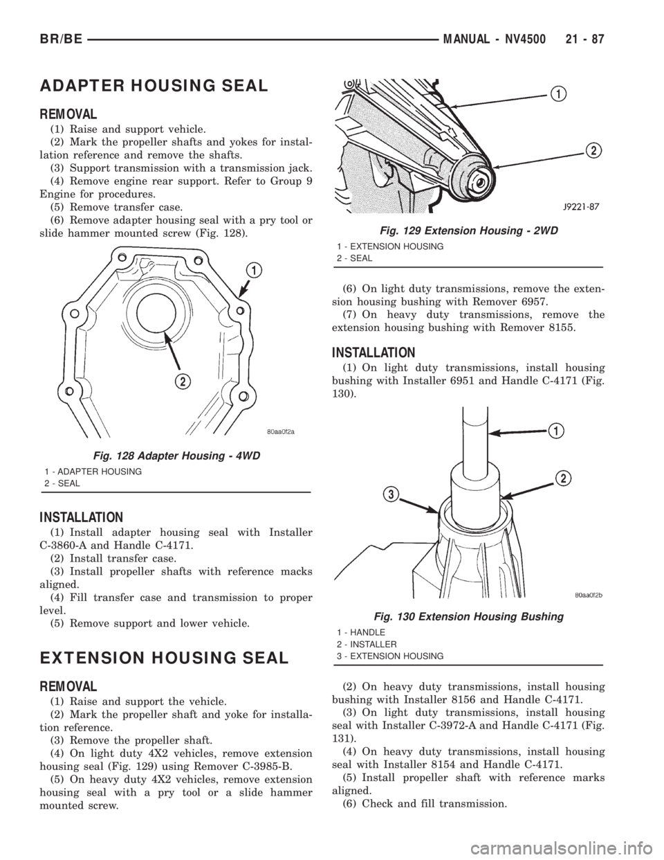
(6) Remove adapter housing seal with a pry tool or
slide hammer mounted screw (Fig. 128).
INSTALLATION
(1) Install adapter housing seal with Installer
C-3860-A and Handle C-4171.
(2) Install transfer case.
(3) Install propeller shafts with reference macks
aligned.
(4) Fill transfer case and transmission to proper
level.
(5) Remove support and lower vehicle.
EXTENSION HOUSING SEAL
REMOVAL
(1) Raise and support the vehicle.
(2) Mark the propeller shaft and yoke for installa-
tion reference.
(3) Remove the propeller shaft.
(4) On light duty 4X2 vehicles, remove extension
housing seal (Fig. 129) using Remover C-3985-B.
(5) On heavy duty 4X2 vehicles, remove extension
housing seal with a pry tool or a slide hammer
mounted screw.(6) On light duty transmissions, remove the exten-
sion housing bushing with Remover 6957.
(7) On heavy duty transmissions, remove the
extension housing bushing with Remover 8155.
INSTALLATION
(1) On light duty transmissions, install housing
bushing with Installer 6951 and Handle C-4171 (Fig.
130).
(2) On heavy duty transmissions, install housing
bushing with Installer 8156 and Handle C-4171.
(3) On light duty transmissions, install housing
seal with Installer C-3972-A and Handle C-4171 (Fig.
131).
(4) On heavy duty transmissions, install housing
seal with Installer 8154 and Handle C-4171.
(5) Install propeller shaft with reference marks
aligned.
(6) Check and fill transmission.
Fig. 128 Adapter Housing - 4WD
1 - ADAPTER HOUSING
2 - SEAL
Fig. 129 Extension Housing - 2WD
1 - EXTENSION HOUSING
2 - SEAL
Fig. 130 Extension Housing Bushing
1 - HANDLE
2 - INSTALLER
3 - EXTENSION HOUSING
BR/BEMANUAL - NV4500 21 - 87
Page 1729 of 2889
A leak at the front of the transmission will be from
either the front bearing retainer or retainer seal.
Lubricant may be seen dripping from the clutch
housing after extended operation. If the leak is
severe, it may also contaminate the clutch disc caus-
ing the disc to slip, grab and or chatter.
A correct lubricant level check can only be made
when the vehicle is level. Also allow the lubricant to
settle for a minute or so before checking. These rec-
ommendations will ensure an accurate check and
avoid an underfill or overfill condition. Always check
the lubricant level after any addition of fluid to avoid
an incorrect lubricant level condition.
HARD SHIFTING
Hard shifting is usually caused by a low lubricant
level, improper or contaminated lubricants. The con-
sequence of using non-recommended lubricants is
noise, excessive wear, internal bind and hard shift-
ing. Substantial lubricant leaks can result in gear,
shift rail, synchro, and bearing damage. If a leak
goes undetected for an extended period, the first indi-
cations of component damage are usually hard shift-
ing and noise.
Component damage, incorrect clutch adjustment or
damaged clutch pressure plate or disc are additional
probable causes of increased shift effort. Incorrect
adjustment or a worn/damaged pressure plate or disc
can cause incorrect release. If clutch problem is
advanced, gear clash during shifts can result. Worn
or damaged synchro rings can cause gear clash when
shifting into any forward gear. In some new or
rebuilt transmissions, new synchro rings may tend to
stick slightly causing hard or noisy shifts. In most
cases this condition will decline as the rings wear-in.
TRANSMISSION NOISE
Most manual transmissions make some noise dur-
ing normal operation. Rotating gears generate a mild
whine that is audible, but generally only at extreme
speeds.
Severe highly audible transmission noise is gener-
ally the initial indicator of a lubricant problem.
Insufficient, improper or contaminated lubricant will
promote rapid wear of gears, synchros, shift rails,
forks and bearings. The overheating caused by a
lubricant problem, can also lead to gear breakage.
REMOVAL
NOTE: Use a heavy duty scissors style transmis-
sion jack for remove of the transmission.
(1) Disconnect battery negative cable.
(2) Shift transmission into Neutral.
(3) Remove screws attaching shift boot to floorpan.
Then slide boot upward on the shift lever.(4) Remove the bolts holding the shift tower to the
isolator plate and transmission gear case.
(5) Remove the shift tower and isolator plate from
the transmission gear case.
(6) Raise and support vehicle.
(7) Remove skid plate, if equipped.
(8) Mark propeller shaft/shafts and axle yokes for
installation reference.
(9) Remove propeller shaft.
(10) Disconnect and remove exhaust system as
necessary.
(11) Disconnect wires at backup light switch.
(12) Support engine with adjustable safety stand
and wood block.
(13) If transmission is to be disassembled for
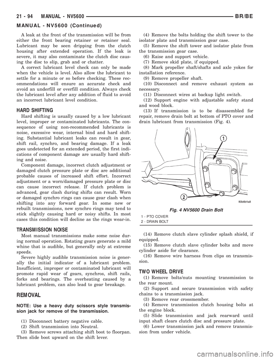
repair, remove drain bolt at bottom of PTO cover and
drain lubricant from transmission (Fig. 4).
(14) Remove clutch slave cylinder splash shield, if
equipped.
(15) Remove clutch slave cylinder bolts and move
cylinder aside for clearance.
(16) Remove wire harness from clips on transmis-
sion.
TWO WHEEL DRIVE
(1) Remove bolts/nuts mounting transmission to
the rear mount.
(2) Support and secure transmission with safety
chains to a transmission jack.
(3) Remove rear crossmember.
(4) Remove transmission clutch housing bolts at
the engine block.
(5) Slide transmission and jack rearward until
input shaft clears clutch disc and pressure plate.
(6) Lower transmission jack and remove transmis-
sion from under vehicle.
Fig. 4 NV5600 Drain Bolt
1 - PTO COVER
2 - DRAIN BOLT
21 - 94 MANUAL - NV5600BR/BE
MANUAL - NV5600 (Continued)
Page 1795 of 2889
ELINE/PROPELLER SHAFT/PROPELLER SHAFT -
REMOVAL)
(12) Disconnect wires from park/neutral position
switch and transmission solenoid.
(13) Disconnect gearshift rod and torque shaft
assembly from transmission.
(14) Disconnect throttle valve cable from transmis-
sion bracket and throttle valve lever.
(15) On4x4models, disconnect shift rod from
transfer case shift lever.
(16)
Support rear of engine with safety stand or jack.
(17) Raise transmission slightly with service jack
to relieve load on crossmember and supports.
(18) Remove bolts securing rear support and cush-
ion to transmission and crossmember. Raise trans-
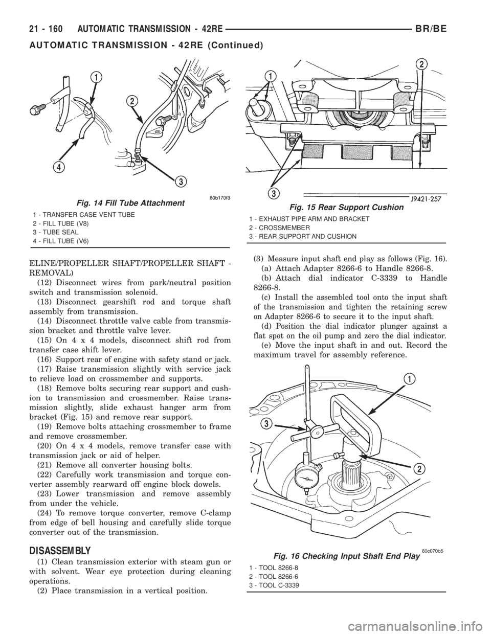
mission slightly, slide exhaust hanger arm from
bracket (Fig. 15) and remove rear support.
(19) Remove bolts attaching crossmember to frame
and remove crossmember.
(20) On4x4models, remove transfer case with
transmission jack or aid of helper.
(21) Remove all converter housing bolts.
(22) Carefully work transmission and torque con-
verter assembly rearward off engine block dowels.
(23) Lower transmission and remove assembly
from under the vehicle.
(24) To remove torque converter, remove C-clamp
from edge of bell housing and carefully slide torque
converter out of the transmission.
DISASSEMBLY
(1) Clean transmission exterior with steam gun or
with solvent. Wear eye protection during cleaning
operations.
(2) Place transmission in a vertical position.(3)
Measure input shaft end play as follows (Fig. 16).
(a) Attach Adapter 8266-6 to Handle 8266-8.
(b) Attach dial indicator C-3339 to Handle
8266-8.
(c)
Install the assembled tool onto the input shaft
of the transmission and tighten the retaining screw
on Adapter 8266-6 to secure it to the input shaft.
(d)Position the dial indicator plunger against a
flat spot on the oil pump and zero the dial indicator.
(e) Move the input shaft in and out. Record the
maximum travel for assembly reference.
Fig. 14 Fill Tube Attachment
1 - TRANSFER CASE VENT TUBE
2 - FILL TUBE (V8)
3 - TUBE SEAL
4 - FILL TUBE (V6)Fig. 15 Rear Support Cushion
1 - EXHAUST PIPE ARM AND BRACKET
2 - CROSSMEMBER
3 - REAR SUPPORT AND CUSHION
Fig. 16 Checking Input Shaft End Play
1 - TOOL 8266-8
2 - TOOL 8266-6
3 - TOOL C-3339
21 - 160 AUTOMATIC TRANSMISSION - 42REBR/BE
AUTOMATIC TRANSMISSION - 42RE (Continued)
Page 1808 of 2889
INSTALLATION
(1) Check torque converter hub and hub drive
notches for sharp edges burrs, scratches, or nicks.
Polish the hub and notches with 320/400 grit paper
and crocus cloth if necessary. The hub must be
smooth to avoid damaging pump seal at installation.
(2) Lubricate pocket in the rear oil pump seal lip
with transmission fluid.
(3) Lubricate converter pilot hub of the crankshaft
with a light coating of MopartHigh Temp Grease.
(4) Align and install converter in oil pump.
(5) Carefully insert converter in oil pump. Then
rotate converter back and forth until fully seated in
pump gears.
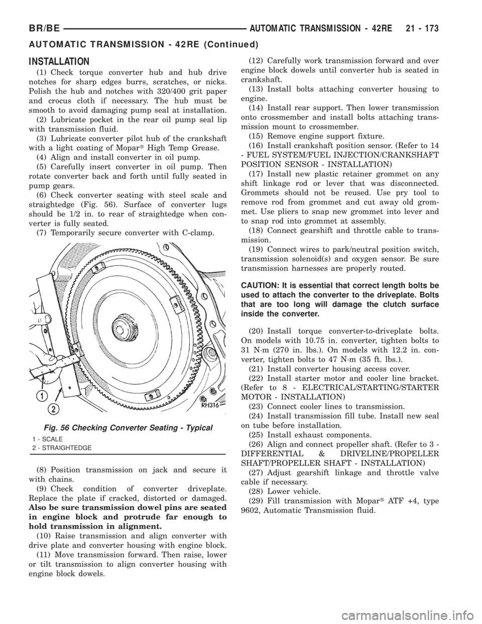
(6) Check converter seating with steel scale and
straightedge (Fig. 56). Surface of converter lugs
should be 1/2 in. to rear of straightedge when con-
verter is fully seated.
(7) Temporarily secure converter with C-clamp.
(8) Position transmission on jack and secure it
with chains.
(9) Check condition of converter driveplate.
Replace the plate if cracked, distorted or damaged.
Also be sure transmission dowel pins are seated
in engine block and protrude far enough to
hold transmission in alignment.
(10) Raise transmission and align converter with
drive plate and converter housing with engine block.
(11) Move transmission forward. Then raise, lower
or tilt transmission to align converter housing with
engine block dowels.(12) Carefully work transmission forward and over
engine block dowels until converter hub is seated in
crankshaft.
(13) Install bolts attaching converter housing to
engine.
(14) Install rear support. Then lower transmission
onto crossmember and install bolts attaching trans-
mission mount to crossmember.
(15) Remove engine support fixture.
(16) Install crankshaft position sensor. (Refer to 14
- FUEL SYSTEM/FUEL INJECTION/CRANKSHAFT
POSITION SENSOR - INSTALLATION)
(17) Install new plastic retainer grommet on any
shift linkage rod or lever that was disconnected.
Grommets should not be reused. Use pry tool to
remove rod from grommet and cut away old grom-
met. Use pliers to snap new grommet into lever and
to snap rod into grommet at assembly.
(18) Connect gearshift and throttle cable to trans-
mission.
(19) Connect wires to park/neutral position switch,
transmission solenoid(s) and oxygen sensor. Be sure
transmission harnesses are properly routed.
CAUTION: It is essential that correct length bolts be
used to attach the converter to the driveplate. Bolts
that are too long will damage the clutch surface
inside the converter.
(20) Install torque converter-to-driveplate bolts.
On models with 10.75 in. converter, tighten bolts to
31 N´m (270 in. lbs.). On models with 12.2 in. con-
verter, tighten bolts to 47 N´m (35 ft. lbs.).
(21) Install converter housing access cover.
(22) Install starter motor and cooler line bracket.
(Refer to 8 - ELECTRICAL/STARTING/STARTER
MOTOR - INSTALLATION)
(23) Connect cooler lines to transmission.
(24) Install transmission fill tube. Install new seal
on tube before installation.
(25) Install exhaust components.
(26) Align and connect propeller shaft. (Refer to 3 -
DIFFERENTIAL & DRIVELINE/PROPELLER
SHAFT/PROPELLER SHAFT - INSTALLATION)
(27) Adjust gearshift linkage and throttle valve
cable if necessary.
(28) Lower vehicle.
(29) Fill transmission with MopartATF +4, type
9602, Automatic Transmission fluid.
Fig. 56 Checking Converter Seating - Typical
1 - SCALE
2 - STRAIGHTEDGE
BR/BEAUTOMATIC TRANSMISSION - 42RE 21 - 173
AUTOMATIC TRANSMISSION - 42RE (Continued)