2001 DODGE RAM seat adjustment
[x] Cancel search: seat adjustmentPage 64 of 2889
SHOCK
DESCRIPTION
The shocks are mounted inside the springs and
attached at the top to brackets with grommets. These
brackets are bolted on the frame with three studs on
a ring. The shock is mounted at the bottom of the
axle below the spring seat.
OPERATION
The shock absorbers dampen the jounce and
rebound of the vehicle over various road conditions.
DIAGNOSIS AND TESTING - SHOCK
A knocking or rattling noise from a shock absorber
may be caused by movement between mounting
bushings and metal brackets or attaching compo-
nents. These noises can usually be stopped by tight-
ening the attaching nuts. If the noise persists,
inspect for damaged and worn bushings, and attach-
ing components. Repair as necessary if any of these
conditions exist.
A squeaking noise from the shock absorber may be
caused by the hydraulic valving and may be intermit-
tent. This condition is not repairable and the shock
absorber must be replaced.
The shock absorbers are not refillable or adjust-
able. If a malfunction occurs, the shock absorbermust be replaced. To test a shock absorber, hold it in
an upright position and force the piston in and out of
the cylinder four or five times. The action throughout
each stroke should be smooth and even.
The shock absorber bushings do not require any
type of lubrication. Do not attempt to stop bushing
noise by lubricating them. Grease and mineral oil-
base lubricants will deteriorate the bushing.
REMOVAL
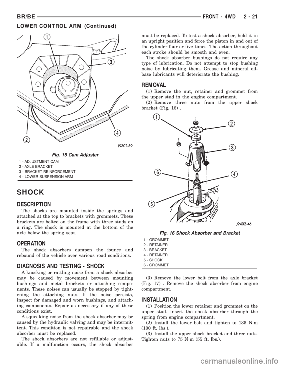
(1) Remove the nut, retainer and grommet from
the upper stud in the engine compartment.
(2) Remove three nuts from the upper shock
bracket (Fig. 16) .
(3) Remove the lower bolt from the axle bracket
(Fig. 17) . Remove the shock absorber from engine
compartment.
INSTALLATION
(1) Position the lower retainer and grommet on the
upper stud. Insert the shock absorber through the
spring from engine compartment.
(2) Install the lower bolt and tighten to 135 N´m
(100 ft. lbs.).
(3) Install the upper shock bracket and three nuts.
Tighten nuts to 75 N´m (55 ft. lbs.).
Fig. 15 Cam Adjuster
1 - ADJUSTMENT CAM
2 - AXLE BRACKET
3 - BRACKET REINFORCEMENT
4 - LOWER SUSPENSION ARM
Fig. 16 Shock Absorber and Bracket
1 - GROMMET
2 - RETAINER
3 - BRACKET
4 - RETAINER
5 - SHOCK
6 - GROMMET
BR/BEFRONT - 4WD 2 - 21
LOWER CONTROL ARM (Continued)
Page 83 of 2889
(5) Position universal joint into pinion yoke for
Dana axles and tighten strap bolts to 29 N´m (22 ft.
lbs.).
(6) Position companion yoke onto the companion
flange for Corporate axles and tighten the bolts to
108 N´m (80 ft. lbs.).
(7) Lower the vehicle.
CENTER BEARING
DESCRIPTION
The two±piece propeller shaft uses a center bearing
to support the shafts. Two types of center bearings
are used. Type 1 is used with the 9 1/4 axle. Type 2
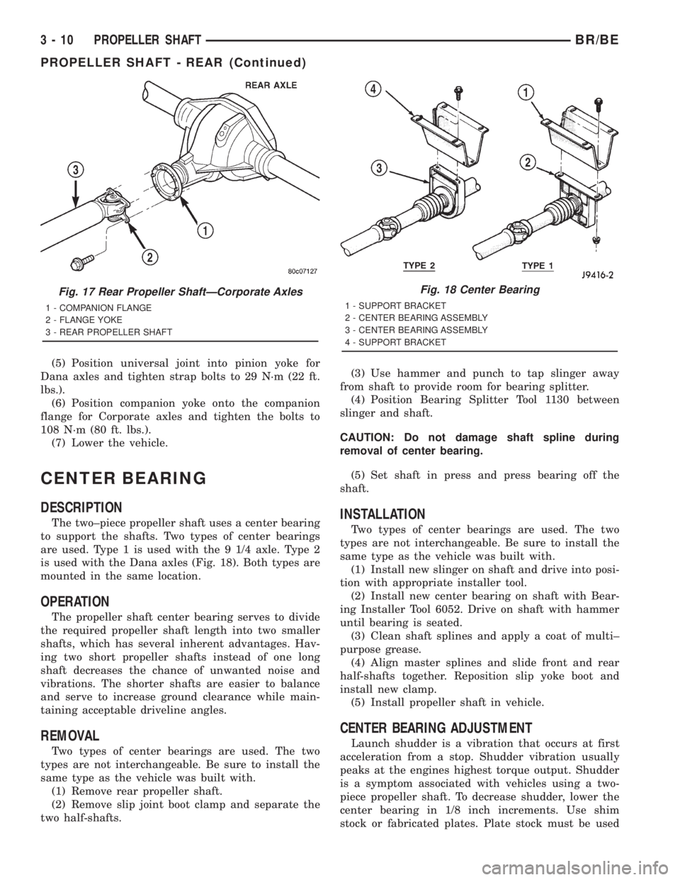
is used with the Dana axles (Fig. 18). Both types are
mounted in the same location.
OPERATION
The propeller shaft center bearing serves to divide
the required propeller shaft length into two smaller
shafts, which has several inherent advantages. Hav-
ing two short propeller shafts instead of one long
shaft decreases the chance of unwanted noise and
vibrations. The shorter shafts are easier to balance
and serve to increase ground clearance while main-
taining acceptable driveline angles.
REMOVAL
Two types of center bearings are used. The two
types are not interchangeable. Be sure to install the
same type as the vehicle was built with.
(1) Remove rear propeller shaft.
(2) Remove slip joint boot clamp and separate the
two half-shafts.(3) Use hammer and punch to tap slinger away
from shaft to provide room for bearing splitter.
(4) Position Bearing Splitter Tool 1130 between
slinger and shaft.
CAUTION: Do not damage shaft spline during
removal of center bearing.
(5) Set shaft in press and press bearing off the
shaft.
INSTALLATION
Two types of center bearings are used. The two
types are not interchangeable. Be sure to install the
same type as the vehicle was built with.
(1) Install new slinger on shaft and drive into posi-
tion with appropriate installer tool.
(2) Install new center bearing on shaft with Bear-
ing Installer Tool 6052. Drive on shaft with hammer
until bearing is seated.
(3) Clean shaft splines and apply a coat of multi±
purpose grease.
(4) Align master splines and slide front and rear
half-shafts together. Reposition slip yoke boot and
install new clamp.
(5) Install propeller shaft in vehicle.
CENTER BEARING ADJUSTMENT
Launch shudder is a vibration that occurs at first
acceleration from a stop. Shudder vibration usually
peaks at the engines highest torque output. Shudder
is a symptom associated with vehicles using a two-
piece propeller shaft. To decrease shudder, lower the
center bearing in 1/8 inch increments. Use shim
stock or fabricated plates. Plate stock must be used
Fig. 17 Rear Propeller ShaftÐCorporate Axles
1 - COMPANION FLANGE
2 - FLANGE YOKE
3 - REAR PROPELLER SHAFT
Fig. 18 Center Bearing
1 - SUPPORT BRACKET
2 - CENTER BEARING ASSEMBLY
3 - CENTER BEARING ASSEMBLY
4 - SUPPORT BRACKET
3 - 10 PROPELLER SHAFTBR/BE
PROPELLER SHAFT - REAR (Continued)
Page 110 of 2889
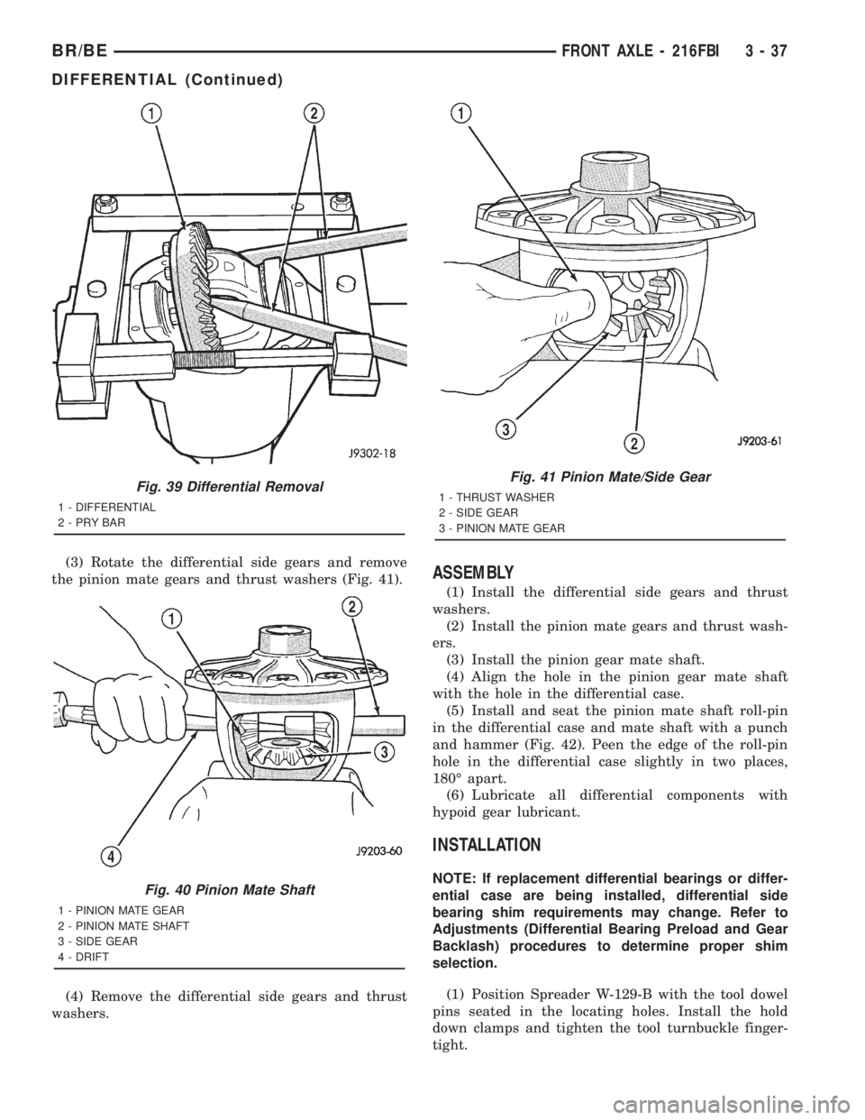
(3) Rotate the differential side gears and remove
the pinion mate gears and thrust washers (Fig. 41).
(4) Remove the differential side gears and thrust
washers.ASSEMBLY
(1) Install the differential side gears and thrust
washers.
(2) Install the pinion mate gears and thrust wash-
ers.
(3) Install the pinion gear mate shaft.
(4) Align the hole in the pinion gear mate shaft
with the hole in the differential case.
(5) Install and seat the pinion mate shaft roll-pin
in the differential case and mate shaft with a punch
and hammer (Fig. 42). Peen the edge of the roll-pin
hole in the differential case slightly in two places,
180É apart.
(6) Lubricate all differential components with
hypoid gear lubricant.
INSTALLATION
NOTE: If replacement differential bearings or differ-
ential case are being installed, differential side
bearing shim requirements may change. Refer to
Adjustments (Differential Bearing Preload and Gear
Backlash) procedures to determine proper shim
selection.
(1) Position Spreader W-129-B with the tool dowel
pins seated in the locating holes. Install the hold
down clamps and tighten the tool turnbuckle finger-
tight.
Fig. 39 Differential Removal
1 - DIFFERENTIAL
2-PRYBAR
Fig. 40 Pinion Mate Shaft
1 - PINION MATE GEAR
2 - PINION MATE SHAFT
3 - SIDE GEAR
4 - DRIFT
Fig. 41 Pinion Mate/Side Gear
1 - THRUST WASHER
2 - SIDE GEAR
3 - PINION MATE GEAR
BR/BEFRONT AXLE - 216FBI 3 - 37
DIFFERENTIAL (Continued)
Page 115 of 2889
INSTALLATION
NOTE: Pinion depth shims are placed between the
rear pinion bearing cone and pinion gear to achieve
proper ring and pinion gear mesh. If ring and pinion
gears are reused, the original pinion depth shim
can be used. Refer to Adjustments (Pinion Gear
Depth) to select the proper shim thickness if ring
and pinion gears are replaced.
(1) Apply Mopar Door Ease stick lubricant to out-
side surface of bearing cups.
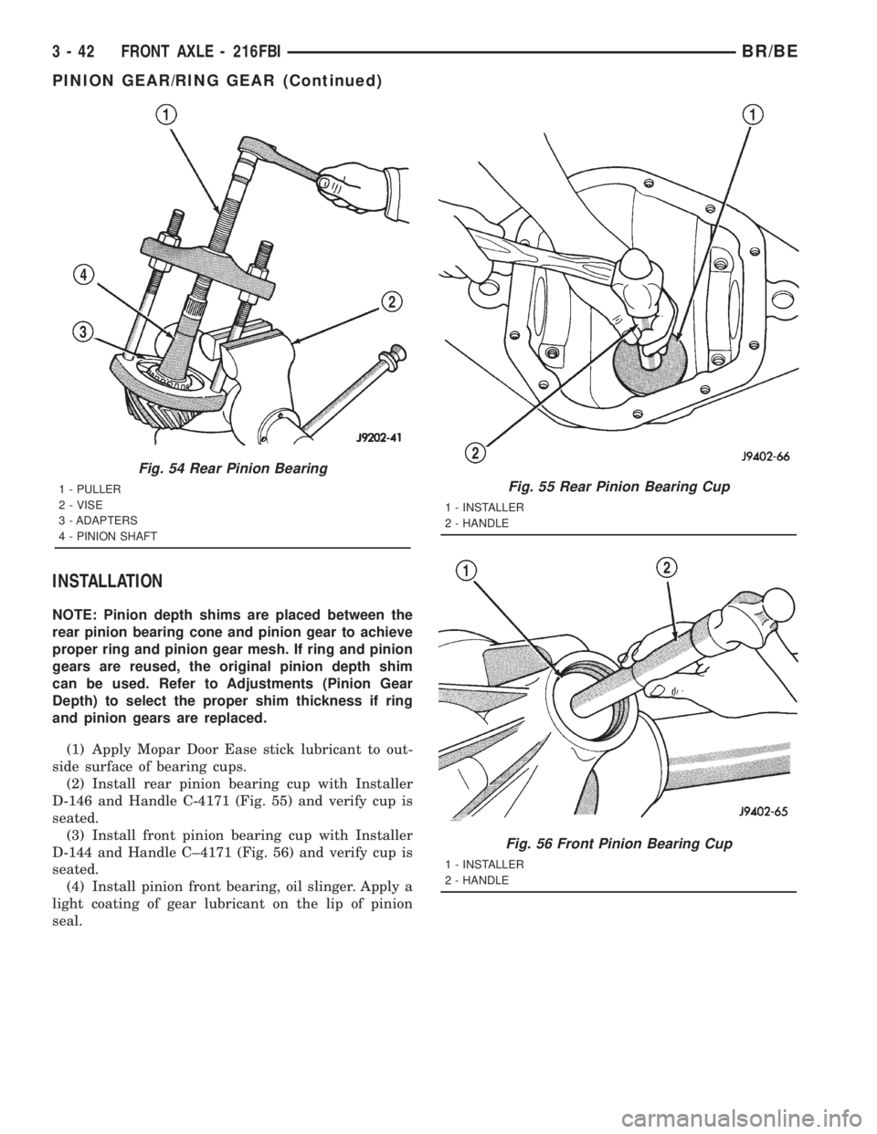
(2) Install rear pinion bearing cup with Installer
D-146 and Handle C-4171 (Fig. 55) and verify cup is
seated.
(3) Install front pinion bearing cup with Installer
D-144 and Handle C±4171 (Fig. 56) and verify cup is
seated.
(4) Install pinion front bearing, oil slinger. Apply a
light coating of gear lubricant on the lip of pinion
seal.
Fig. 54 Rear Pinion Bearing
1 - PULLER
2 - VISE
3 - ADAPTERS
4 - PINION SHAFTFig. 55 Rear Pinion Bearing Cup
1 - INSTALLER
2 - HANDLE
Fig. 56 Front Pinion Bearing Cup
1 - INSTALLER
2 - HANDLE
3 - 42 FRONT AXLE - 216FBIBR/BE
PINION GEAR/RING GEAR (Continued)
Page 142 of 2889
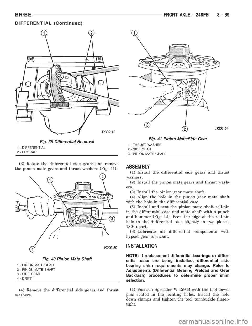
(3) Rotate the differential side gears and remove
the pinion mate gears and thrust washers (Fig. 41).
(4) Remove the differential side gears and thrust
washers.ASSEMBLY
(1) Install the differential side gears and thrust
washers.
(2) Install the pinion mate gears and thrust wash-
ers.
(3) Install the pinion gear mate shaft.
(4) Align the hole in the pinion gear mate shaft
with the hole in the differential case.
(5) Install and seat the pinion mate shaft roll-pin
in the differential case and mate shaft with a punch
and hammer (Fig. 42). Peen the edge of the roll-pin
hole in the differential case slightly in two places,
180É apart.
(6) Lubricate all differential components with
hypoid gear lubricant.
INSTALLATION
NOTE: If replacement differential bearings or differ-
ential case are being installed, differential side
bearing shim requirements may change. Refer to
Adjustments (Differential Bearing Preload and Gear
Backlash) procedures to determine proper shim
selection.
(1) Position Spreader W-129-B with the tool dowel
pins seated in the locating holes. Install the hold
down clamps and tighten the tool turnbuckle finger-
tight.
Fig. 39 Differential Removal
1 - DIFFERENTIAL
2-PRYBAR
Fig. 40 Pinion Mate Shaft
1 - PINION MATE GEAR
2 - PINION MATE SHAFT
3 - SIDE GEAR
4 - DRIFT
Fig. 41 Pinion Mate/Side Gear
1 - THRUST WASHER
2 - SIDE GEAR
3 - PINION MATE GEAR
BR/BEFRONT AXLE - 248FBI 3 - 69
DIFFERENTIAL (Continued)
Page 147 of 2889
INSTALLATION
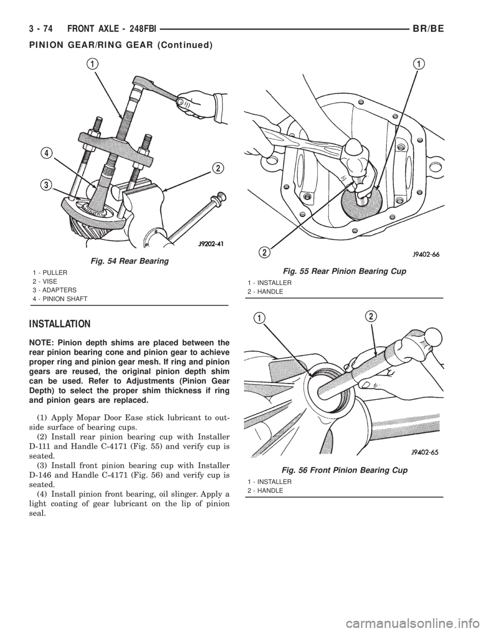
NOTE: Pinion depth shims are placed between the
rear pinion bearing cone and pinion gear to achieve
proper ring and pinion gear mesh. If ring and pinion
gears are reused, the original pinion depth shim
can be used. Refer to Adjustments (Pinion Gear
Depth) to select the proper shim thickness if ring
and pinion gears are replaced.
(1) Apply Mopar Door Ease stick lubricant to out-
side surface of bearing cups.
(2) Install rear pinion bearing cup with Installer
D-111 and Handle C-4171 (Fig. 55) and verify cup is
seated.
(3) Install front pinion bearing cup with Installer
D-146 and Handle C-4171 (Fig. 56) and verify cup is
seated.
(4) Install pinion front bearing, oil slinger. Apply a
light coating of gear lubricant on the lip of pinion
seal.
Fig. 54 Rear Bearing
1 - PULLER
2 - VISE
3 - ADAPTERS
4 - PINION SHAFTFig. 55 Rear Pinion Bearing Cup
1 - INSTALLER
2 - HANDLE
Fig. 56 Front Pinion Bearing Cup
1 - INSTALLER
2 - HANDLE
3 - 74 FRONT AXLE - 248FBIBR/BE
PINION GEAR/RING GEAR (Continued)
Page 159 of 2889
(5) Assemble Dial Indicator C-3339 into Scooter
Block D-115-2 and secure set screw.
(6) Place Scooter Block/Dial Indicator in position
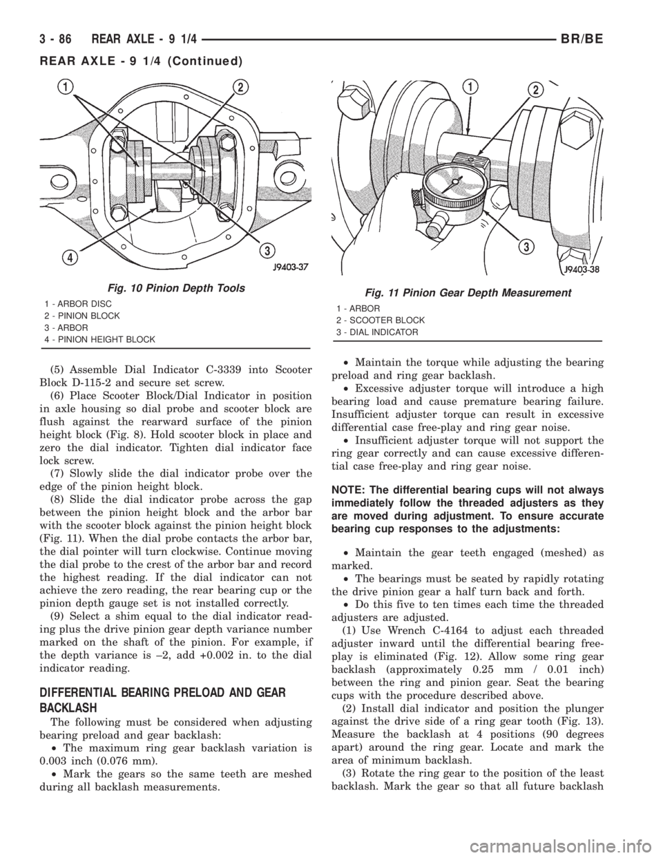
in axle housing so dial probe and scooter block are
flush against the rearward surface of the pinion
height block (Fig. 8). Hold scooter block in place and
zero the dial indicator. Tighten dial indicator face
lock screw.
(7) Slowly slide the dial indicator probe over the
edge of the pinion height block.
(8) Slide the dial indicator probe across the gap
between the pinion height block and the arbor bar
with the scooter block against the pinion height block
(Fig. 11). When the dial probe contacts the arbor bar,
the dial pointer will turn clockwise. Continue moving
the dial probe to the crest of the arbor bar and record
the highest reading. If the dial indicator can not
achieve the zero reading, the rear bearing cup or the
pinion depth gauge set is not installed correctly.
(9) Select a shim equal to the dial indicator read-
ing plus the drive pinion gear depth variance number
marked on the shaft of the pinion. For example, if
the depth variance is ±2, add +0.002 in. to the dial
indicator reading.
DIFFERENTIAL BEARING PRELOAD AND GEAR
BACKLASH
The following must be considered when adjusting
bearing preload and gear backlash:
²The maximum ring gear backlash variation is
0.003 inch (0.076 mm).
²Mark the gears so the same teeth are meshed
during all backlash measurements.²Maintain the torque while adjusting the bearing
preload and ring gear backlash.
²Excessive adjuster torque will introduce a high
bearing load and cause premature bearing failure.
Insufficient adjuster torque can result in excessive
differential case free-play and ring gear noise.
²Insufficient adjuster torque will not support the
ring gear correctly and can cause excessive differen-
tial case free-play and ring gear noise.
NOTE: The differential bearing cups will not always
immediately follow the threaded adjusters as they
are moved during adjustment. To ensure accurate
bearing cup responses to the adjustments:
²Maintain the gear teeth engaged (meshed) as
marked.
²The bearings must be seated by rapidly rotating
the drive pinion gear a half turn back and forth.
²Do this five to ten times each time the threaded
adjusters are adjusted.
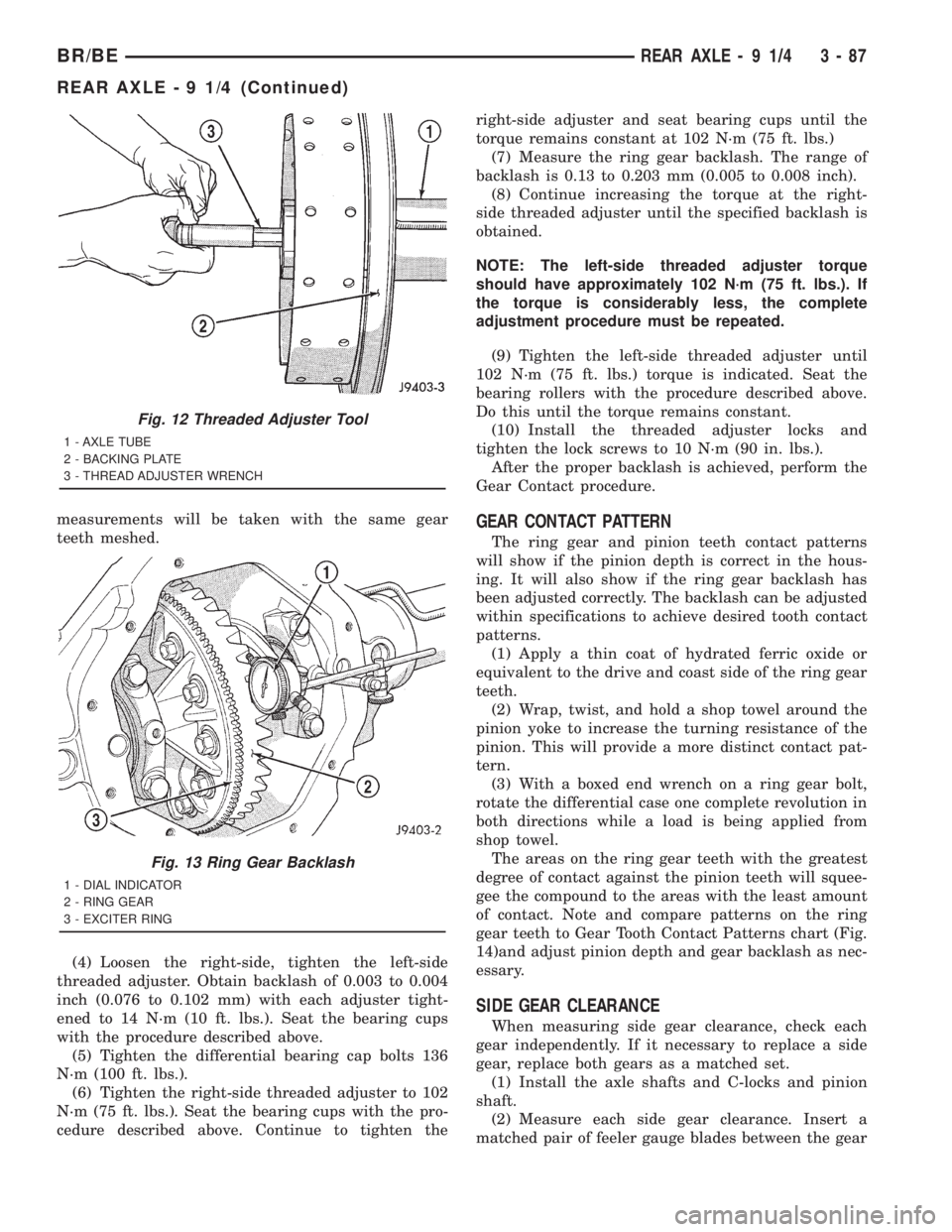
(1) Use Wrench C-4164 to adjust each threaded
adjuster inward until the differential bearing free-
play is eliminated (Fig. 12). Allow some ring gear
backlash (approximately 0.25 mm / 0.01 inch)
between the ring and pinion gear. Seat the bearing
cups with the procedure described above.
(2) Install dial indicator and position the plunger
against the drive side of a ring gear tooth (Fig. 13).
Measure the backlash at 4 positions (90 degrees
apart) around the ring gear. Locate and mark the
area of minimum backlash.
(3) Rotate the ring gear to the position of the least
backlash. Mark the gear so that all future backlash
Fig. 10 Pinion Depth Tools
1 - ARBOR DISC
2 - PINION BLOCK
3 - ARBOR
4 - PINION HEIGHT BLOCKFig. 11 Pinion Gear Depth Measurement
1 - ARBOR
2 - SCOOTER BLOCK
3 - DIAL INDICATOR
3 - 86 REAR AXLE-91/4BR/BE
REAR AXLE - 9 1/4 (Continued)
Page 160 of 2889
measurements will be taken with the same gear
teeth meshed.
(4) Loosen the right-side, tighten the left-side
threaded adjuster. Obtain backlash of 0.003 to 0.004
inch (0.076 to 0.102 mm) with each adjuster tight-
ened to 14 N´m (10 ft. lbs.). Seat the bearing cups
with the procedure described above.
(5) Tighten the differential bearing cap bolts 136
N´m (100 ft. lbs.).
(6) Tighten the right-side threaded adjuster to 102
N´m (75 ft. lbs.). Seat the bearing cups with the pro-
cedure described above. Continue to tighten theright-side adjuster and seat bearing cups until the
torque remains constant at 102 N´m (75 ft. lbs.)
(7) Measure the ring gear backlash. The range of
backlash is 0.13 to 0.203 mm (0.005 to 0.008 inch).
(8) Continue increasing the torque at the right-
side threaded adjuster until the specified backlash is
obtained.
NOTE: The left-side threaded adjuster torque
should have approximately 102 N´m (75 ft. lbs.). If
the torque is considerably less, the complete
adjustment procedure must be repeated.
(9) Tighten the left-side threaded adjuster until
102 N´m (75 ft. lbs.) torque is indicated. Seat the
bearing rollers with the procedure described above.
Do this until the torque remains constant.
(10) Install the threaded adjuster locks and
tighten the lock screws to 10 N´m (90 in. lbs.).
After the proper backlash is achieved, perform the
Gear Contact procedure.GEAR CONTACT PATTERN
The ring gear and pinion teeth contact patterns
will show if the pinion depth is correct in the hous-
ing. It will also show if the ring gear backlash has
been adjusted correctly. The backlash can be adjusted
within specifications to achieve desired tooth contact
patterns.
(1) Apply a thin coat of hydrated ferric oxide or
equivalent to the drive and coast side of the ring gear
teeth.
(2) Wrap, twist, and hold a shop towel around the
pinion yoke to increase the turning resistance of the
pinion. This will provide a more distinct contact pat-
tern.
(3) With a boxed end wrench on a ring gear bolt,
rotate the differential case one complete revolution in
both directions while a load is being applied from
shop towel.
The areas on the ring gear teeth with the greatest
degree of contact against the pinion teeth will squee-
gee the compound to the areas with the least amount
of contact. Note and compare patterns on the ring
gear teeth to Gear Tooth Contact Patterns chart (Fig.
14)and adjust pinion depth and gear backlash as nec-
essary.
SIDE GEAR CLEARANCE
When measuring side gear clearance, check each
gear independently. If it necessary to replace a side
gear, replace both gears as a matched set.
(1) Install the axle shafts and C-locks and pinion
shaft.
(2) Measure each side gear clearance. Insert a
matched pair of feeler gauge blades between the gear
Fig. 12 Threaded Adjuster Tool
1 - AXLE TUBE
2 - BACKING PLATE
3 - THREAD ADJUSTER WRENCH
Fig. 13 Ring Gear Backlash
1 - DIAL INDICATOR
2 - RING GEAR
3 - EXCITER RING
BR/BEREAR AXLE - 9 1/4 3 - 87
REAR AXLE - 9 1/4 (Continued)