2001 DODGE RAM seat adjustment
[x] Cancel search: seat adjustmentPage 171 of 2889
ASSEMBLY
(1) Install differential side gears and thrust wash-
ers.
(2) Install differential pinion and thrust washers.
(3) Install the pinion shaft.
(4) Align the hole in the pinion shaft with the hole
in the differential case and install the pinion shaft
lock screw.
(5) Lubricate all differential components with
hypoid gear lubricant.
INSTALLATION
(1) Apply a coating of hypoid gear lubricant to the
differential bearings, bearing cups, and threaded
adjusters. A dab of grease can be used to keep the
adjusters in position. Carefully position the assem-
bled differential case in the housing.
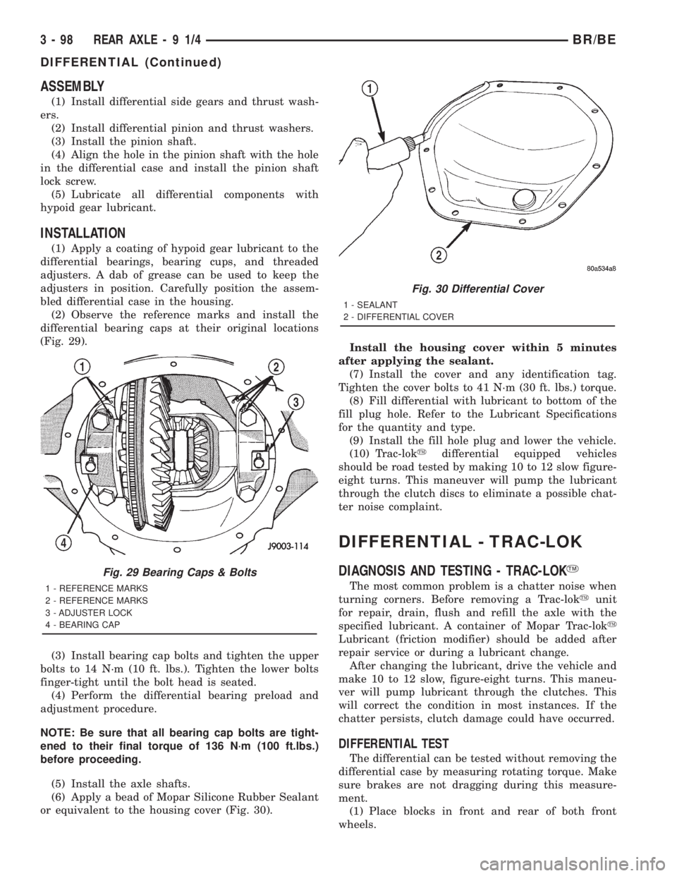
(2) Observe the reference marks and install the
differential bearing caps at their original locations
(Fig. 29).
(3) Install bearing cap bolts and tighten the upper
bolts to 14 N´m (10 ft. lbs.). Tighten the lower bolts
finger-tight until the bolt head is seated.
(4) Perform the differential bearing preload and
adjustment procedure.
NOTE: Be sure that all bearing cap bolts are tight-
ened to their final torque of 136 N´m (100 ft.lbs.)
before proceeding.
(5) Install the axle shafts.
(6) Apply a bead of Mopar Silicone Rubber Sealant
or equivalent to the housing cover (Fig. 30).Install the housing cover within 5 minutes
after applying the sealant.
(7) Install the cover and any identification tag.
Tighten the cover bolts to 41 N´m (30 ft. lbs.) torque.
(8) Fill differential with lubricant to bottom of the
fill plug hole. Refer to the Lubricant Specifications
for the quantity and type.
(9) Install the fill hole plug and lower the vehicle.
(10) Trac-lokydifferential equipped vehicles
should be road tested by making 10 to 12 slow figure-
eight turns. This maneuver will pump the lubricant
through the clutch discs to eliminate a possible chat-
ter noise complaint.
DIFFERENTIAL - TRAC-LOK
DIAGNOSIS AND TESTING - TRAC-LOKY
The most common problem is a chatter noise when
turning corners. Before removing a Trac-lokyunit
for repair, drain, flush and refill the axle with the
specified lubricant. A container of Mopar Trac-loky
Lubricant (friction modifier) should be added after
repair service or during a lubricant change.
After changing the lubricant, drive the vehicle and
make 10 to 12 slow, figure-eight turns. This maneu-
ver will pump lubricant through the clutches. This
will correct the condition in most instances. If the
chatter persists, clutch damage could have occurred.
DIFFERENTIAL TEST
The differential can be tested without removing the
differential case by measuring rotating torque. Make
sure brakes are not dragging during this measure-
ment.
(1) Place blocks in front and rear of both front
wheels.
Fig. 29 Bearing Caps & Bolts
1 - REFERENCE MARKS
2 - REFERENCE MARKS
3 - ADJUSTER LOCK
4 - BEARING CAP
Fig. 30 Differential Cover
1 - SEALANT
2 - DIFFERENTIAL COVER
3 - 98 REAR AXLE-91/4BR/BE
DIFFERENTIAL (Continued)
Page 178 of 2889
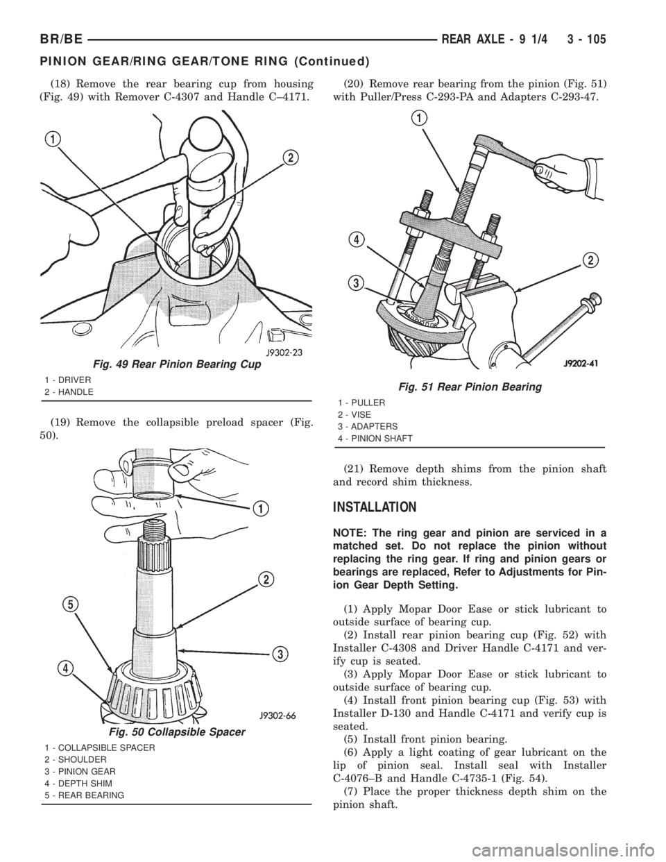
(18) Remove the rear bearing cup from housing
(Fig. 49) with Remover C-4307 and Handle C±4171.
(19) Remove the collapsible preload spacer (Fig.
50).(20) Remove rear bearing from the pinion (Fig. 51)
with Puller/Press C-293-PA and Adapters C-293-47.
(21) Remove depth shims from the pinion shaft
and record shim thickness.
INSTALLATION
NOTE: The ring gear and pinion are serviced in a
matched set. Do not replace the pinion without
replacing the ring gear. If ring and pinion gears or
bearings are replaced, Refer to Adjustments for Pin-
ion Gear Depth Setting.
(1) Apply Mopar Door Ease or stick lubricant to
outside surface of bearing cup.
(2) Install rear pinion bearing cup (Fig. 52) with
Installer C-4308 and Driver Handle C-4171 and ver-
ify cup is seated.
(3) Apply Mopar Door Ease or stick lubricant to
outside surface of bearing cup.
(4) Install front pinion bearing cup (Fig. 53) with
Installer D-130 and Handle C-4171 and verify cup is
seated.
(5) Install front pinion bearing.
(6) Apply a light coating of gear lubricant on the
lip of pinion seal. Install seal with Installer
C-4076±B and Handle C-4735-1 (Fig. 54).
(7) Place the proper thickness depth shim on the
pinion shaft.
Fig. 49 Rear Pinion Bearing Cup
1 - DRIVER
2 - HANDLE
Fig. 50 Collapsible Spacer
1 - COLLAPSIBLE SPACER
2 - SHOULDER
3 - PINION GEAR
4 - DEPTH SHIM
5 - REAR BEARING
Fig. 51 Rear Pinion Bearing
1 - PULLER
2 - VISE
3 - ADAPTERS
4 - PINION SHAFT
BR/BEREAR AXLE - 9 1/4 3 - 105
PINION GEAR/RING GEAR/TONE RING (Continued)
Page 190 of 2889
(2) Remove factory installed shims from differen-
tial case.
(3) Install ring gear on differential case and
tighten bolts to specification.
(4) Install dummy side bearings D-343 on differen-
tial case.
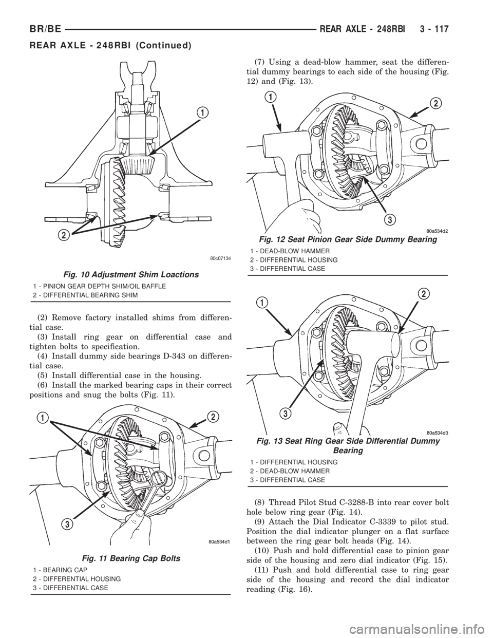
(5) Install differential case in the housing.
(6) Install the marked bearing caps in their correct
positions and snug the bolts (Fig. 11).(7) Using a dead-blow hammer, seat the differen-
tial dummy bearings to each side of the housing (Fig.
12) and (Fig. 13).
(8) Thread Pilot Stud C-3288-B into rear cover bolt
hole below ring gear (Fig. 14).
(9) Attach the Dial Indicator C-3339 to pilot stud.
Position the dial indicator plunger on a flat surface
between the ring gear bolt heads (Fig. 14).
(10) Push and hold differential case to pinion gear
side of the housing and zero dial indicator (Fig. 15).
(11) Push and hold differential case to ring gear
side of the housing and record the dial indicator
reading (Fig. 16).
Fig. 10 Adjustment Shim Loactions
1 - PINION GEAR DEPTH SHIM/OIL BAFFLE
2 - DIFFERENTIAL BEARING SHIM
Fig. 11 Bearing Cap Bolts
1 - BEARING CAP
2 - DIFFERENTIAL HOUSING
3 - DIFFERENTIAL CASE
Fig. 12 Seat Pinion Gear Side Dummy Bearing
1 - DEAD-BLOW HAMMER
2 - DIFFERENTIAL HOUSING
3 - DIFFERENTIAL CASE
Fig. 13 Seat Ring Gear Side Differential Dummy
Bearing
1 - DIFFERENTIAL HOUSING
2 - DEAD-BLOW HAMMER
3 - DIFFERENTIAL CASE
BR/BEREAR AXLE - 248RBI 3 - 117
REAR AXLE - 248RBI (Continued)
Page 202 of 2889
INSTALLATION
NOTE: If replacement differential bearings or differ-
ential case are being installed, differential side
bearing shim requirements may change. Refer to
Adjustments (Differential Bearing Preload and Gear
Backlash) procedures to determine proper shim
selection.
(1) Position Spreader W-129-B with the tool dowel
pins seated in the locating holes. Install the hold
down clamps and tighten the tool turnbuckle finger-
tight.
(2) Install a Pilot Stud C-3288-B at the left side of
the differential housing and attach dial indicator to
the pilot stud. Load the indicator plunger against the
opposite side of the housing and zero the dial indica-
tor.
(3) Spread the housing enough to install the case
in the housing. Measure the distance with the dial
indicator.
CAUTION: Do not spread over 0.50 mm (0.020 in). If
the housing is over-spread, it could be distorted or
damaged.
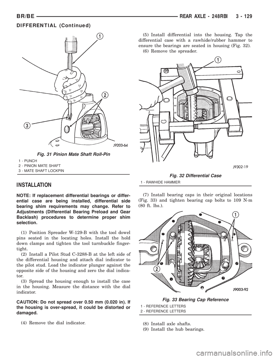
(4) Remove the dial indicator.(5) Install differential into the housing. Tap the
differential case with a rawhide/rubber hammer to
ensure the bearings are seated in housing (Fig. 32).
(6) Remove the spreader.
(7) Install bearing caps in their original locations
(Fig. 33) and tighten bearing cap bolts to 109 N´m
(80 ft. lbs.).
(8) Install axle shafts.
(9) Install the hub bearings.
Fig. 31 Pinion Mate Shaft Roll-Pin
1 - PUNCH
2 - PINION MATE SHAFT
3 - MATE SHAFT LOCKPIN
Fig. 32 Differential Case
1 - RAWHIDE HAMMER
Fig. 33 Bearing Cap Reference
1 - REFERENCE LETTERS
2 - REFERENCE LETTERS
BR/BEREAR AXLE - 248RBI 3 - 129
DIFFERENTIAL (Continued)
Page 221 of 2889
(2) Remove factory installed shims from differen-
tial case.
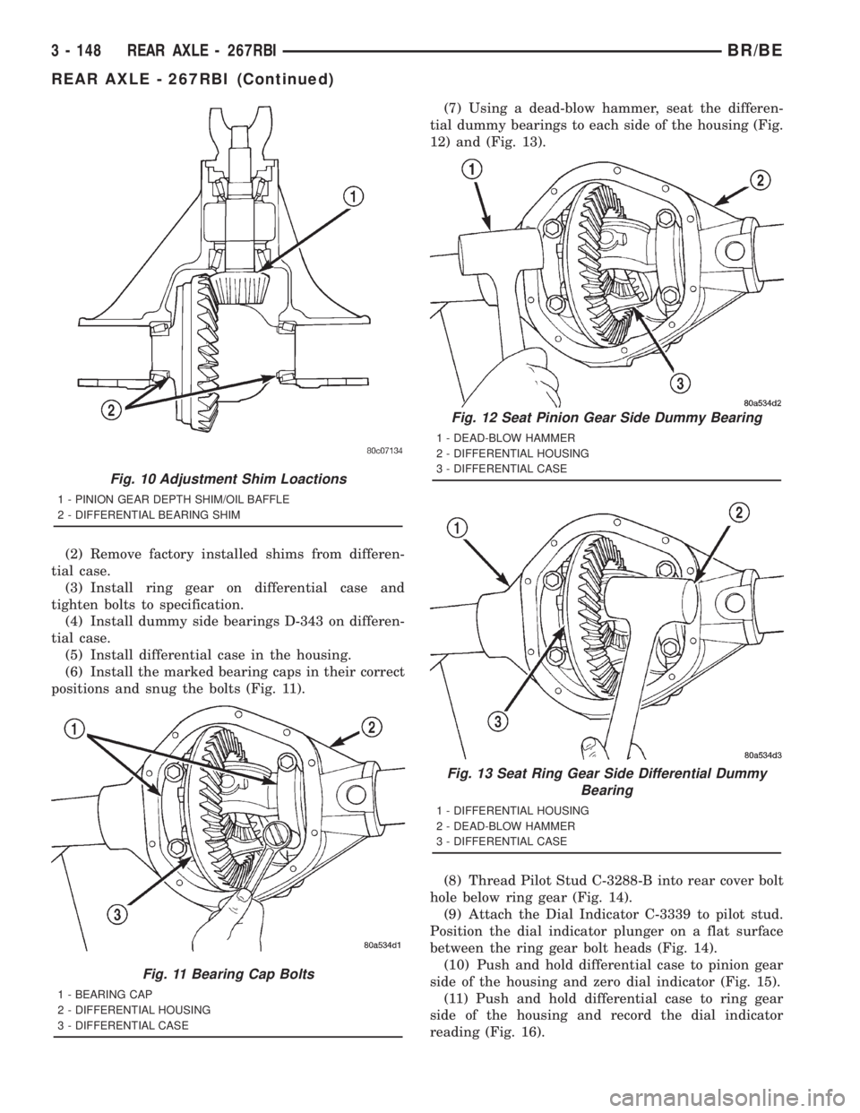
(3) Install ring gear on differential case and
tighten bolts to specification.
(4) Install dummy side bearings D-343 on differen-
tial case.
(5) Install differential case in the housing.
(6) Install the marked bearing caps in their correct
positions and snug the bolts (Fig. 11).(7) Using a dead-blow hammer, seat the differen-
tial dummy bearings to each side of the housing (Fig.
12) and (Fig. 13).
(8) Thread Pilot Stud C-3288-B into rear cover bolt
hole below ring gear (Fig. 14).
(9) Attach the Dial Indicator C-3339 to pilot stud.
Position the dial indicator plunger on a flat surface
between the ring gear bolt heads (Fig. 14).
(10) Push and hold differential case to pinion gear
side of the housing and zero dial indicator (Fig. 15).
(11) Push and hold differential case to ring gear
side of the housing and record the dial indicator
reading (Fig. 16).
Fig. 10 Adjustment Shim Loactions
1 - PINION GEAR DEPTH SHIM/OIL BAFFLE
2 - DIFFERENTIAL BEARING SHIM
Fig. 11 Bearing Cap Bolts
1 - BEARING CAP
2 - DIFFERENTIAL HOUSING
3 - DIFFERENTIAL CASE
Fig. 12 Seat Pinion Gear Side Dummy Bearing
1 - DEAD-BLOW HAMMER
2 - DIFFERENTIAL HOUSING
3 - DIFFERENTIAL CASE
Fig. 13 Seat Ring Gear Side Differential Dummy
Bearing
1 - DIFFERENTIAL HOUSING
2 - DEAD-BLOW HAMMER
3 - DIFFERENTIAL CASE
3 - 148 REAR AXLE - 267RBIBR/BE
REAR AXLE - 267RBI (Continued)
Page 232 of 2889
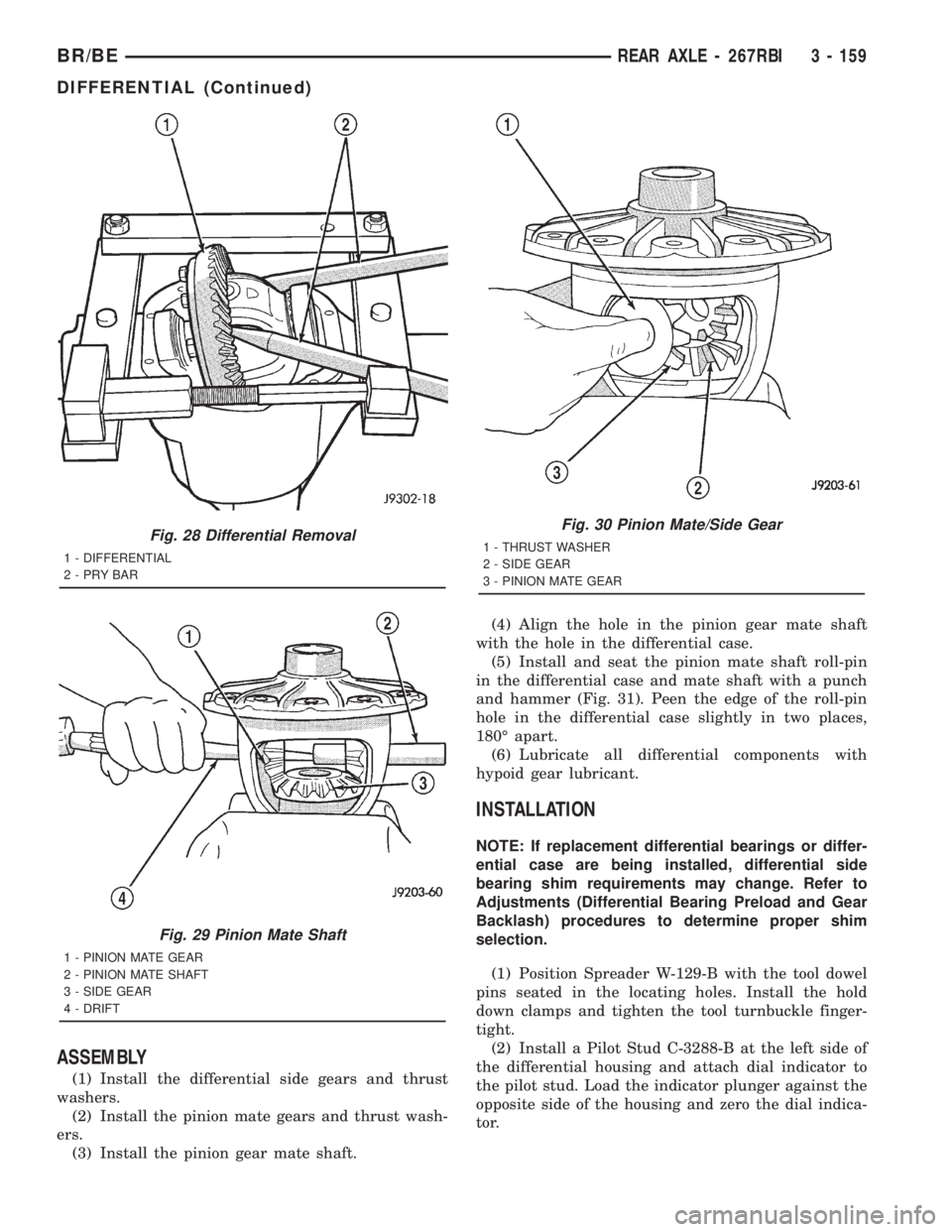
ASSEMBLY
(1) Install the differential side gears and thrust
washers.
(2) Install the pinion mate gears and thrust wash-
ers.
(3) Install the pinion gear mate shaft.(4) Align the hole in the pinion gear mate shaft
with the hole in the differential case.
(5) Install and seat the pinion mate shaft roll-pin
in the differential case and mate shaft with a punch
and hammer (Fig. 31). Peen the edge of the roll-pin
hole in the differential case slightly in two places,
180É apart.
(6) Lubricate all differential components with
hypoid gear lubricant.
INSTALLATION
NOTE: If replacement differential bearings or differ-
ential case are being installed, differential side
bearing shim requirements may change. Refer to
Adjustments (Differential Bearing Preload and Gear
Backlash) procedures to determine proper shim
selection.
(1) Position Spreader W-129-B with the tool dowel
pins seated in the locating holes. Install the hold
down clamps and tighten the tool turnbuckle finger-
tight.
(2) Install a Pilot Stud C-3288-B at the left side of
the differential housing and attach dial indicator to
the pilot stud. Load the indicator plunger against the
opposite side of the housing and zero the dial indica-
tor.
Fig. 28 Differential Removal
1 - DIFFERENTIAL
2-PRYBAR
Fig. 29 Pinion Mate Shaft
1 - PINION MATE GEAR
2 - PINION MATE SHAFT
3 - SIDE GEAR
4 - DRIFT
Fig. 30 Pinion Mate/Side Gear
1 - THRUST WASHER
2 - SIDE GEAR
3 - PINION MATE GEAR
BR/BEREAR AXLE - 267RBI 3 - 159
DIFFERENTIAL (Continued)
Page 240 of 2889
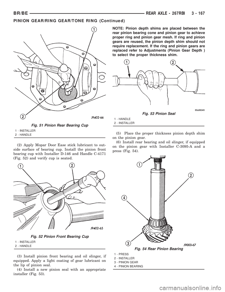
(2) Apply Mopar Door Ease stick lubricant to out-
side surface of bearing cup. Install the pinion front
bearing cup with Installer D-146 and Handle C-4171
(Fig. 52) and verify cup is seated.
(3) Install pinion front bearing and oil slinger, if
equipped. Apply a light coating of gear lubricant on
the lip of pinion seal.
(4) Install a new pinion seal with an appropriate
installer (Fig. 53).NOTE: Pinion depth shims are placed between the
rear pinion bearing cone and pinion gear to achieve
proper ring and pinion gear mesh. If ring and pinion
gears are reused, the pinion depth shim should not
require replacement. If the ring and pinion gears are
replaced refer to Adjustments (Pinion Gear Depth )
to select the proper thickness shim.
(5) Place the proper thickness pinion depth shim
on the pinion gear.
(6) Install rear bearing and oil slinger, if equipped
on the pinion gear with Installer C-3095-A and a
press (Fig. 54).
Fig. 51 Pinion Rear Bearing Cup
1 - INSTALLER
2 - HANDLE
Fig. 52 Pinion Front Bearing Cup
1 - INSTALLER
2 - HANDLE
Fig. 53 Pinion Seal
1 - HANDLE
2 - INSTALLER
Fig. 54 Rear Pinion Bearing
1 - PRESS
2 - INSTALLER
3 - PINION GEAR
4 - PINION BEARING
BR/BEREAR AXLE - 267RBI 3 - 167
PINION GEAR/RING GEAR/TONE RING (Continued)
Page 250 of 2889
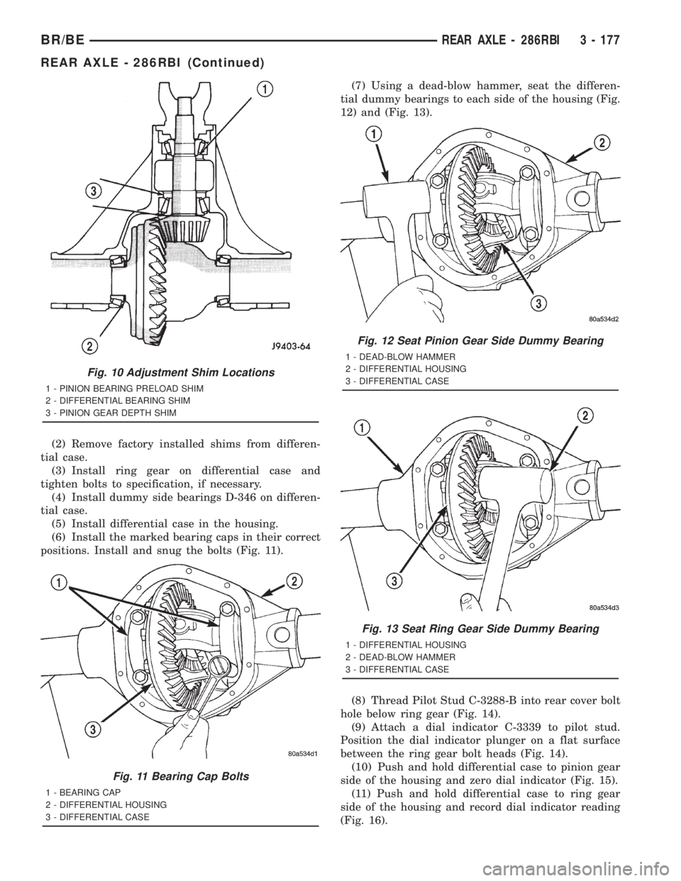
(2) Remove factory installed shims from differen-
tial case.
(3) Install ring gear on differential case and
tighten bolts to specification, if necessary.
(4) Install dummy side bearings D-346 on differen-
tial case.
(5) Install differential case in the housing.
(6) Install the marked bearing caps in their correct
positions. Install and snug the bolts (Fig. 11).(7) Using a dead-blow hammer, seat the differen-
tial dummy bearings to each side of the housing (Fig.
12) and (Fig. 13).
(8) Thread Pilot Stud C-3288-B into rear cover bolt
hole below ring gear (Fig. 14).
(9) Attach a dial indicator C-3339 to pilot stud.
Position the dial indicator plunger on a flat surface
between the ring gear bolt heads (Fig. 14).
(10) Push and hold differential case to pinion gear
side of the housing and zero dial indicator (Fig. 15).
(11) Push and hold differential case to ring gear
side of the housing and record dial indicator reading
(Fig. 16).
Fig. 10 Adjustment Shim Locations
1 - PINION BEARING PRELOAD SHIM
2 - DIFFERENTIAL BEARING SHIM
3 - PINION GEAR DEPTH SHIM
Fig. 11 Bearing Cap Bolts
1 - BEARING CAP
2 - DIFFERENTIAL HOUSING
3 - DIFFERENTIAL CASE
Fig. 12 Seat Pinion Gear Side Dummy Bearing
1 - DEAD-BLOW HAMMER
2 - DIFFERENTIAL HOUSING
3 - DIFFERENTIAL CASE
Fig. 13 Seat Ring Gear Side Dummy Bearing
1 - DIFFERENTIAL HOUSING
2 - DEAD-BLOW HAMMER
3 - DIFFERENTIAL CASE
BR/BEREAR AXLE - 286RBI 3 - 177
REAR AXLE - 286RBI (Continued)