2001 DODGE RAM seat adjustment
[x] Cancel search: seat adjustmentPage 261 of 2889
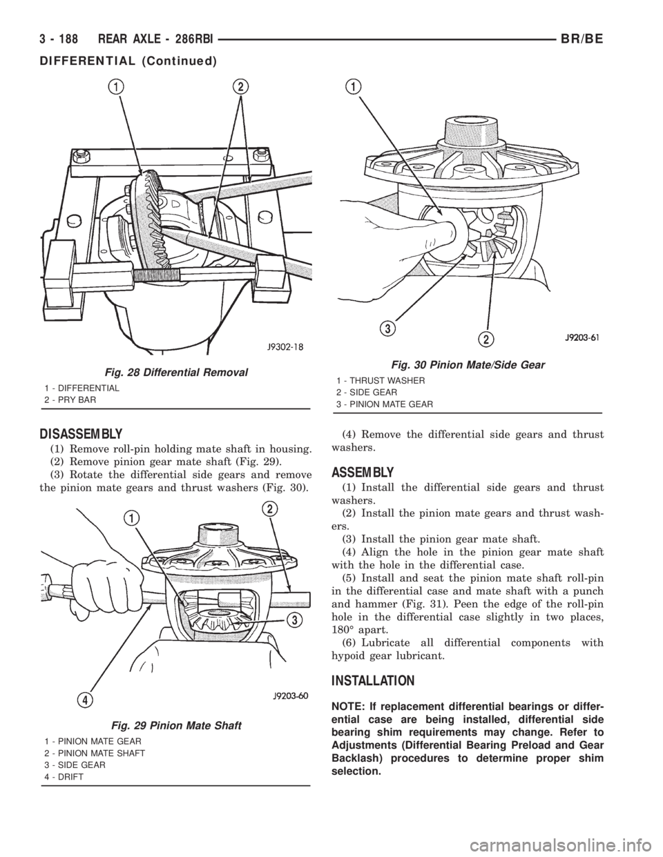
DISASSEMBLY
(1) Remove roll-pin holding mate shaft in housing.
(2) Remove pinion gear mate shaft (Fig. 29).
(3) Rotate the differential side gears and remove
the pinion mate gears and thrust washers (Fig. 30).(4) Remove the differential side gears and thrust
washers.
ASSEMBLY
(1) Install the differential side gears and thrust
washers.
(2) Install the pinion mate gears and thrust wash-
ers.
(3) Install the pinion gear mate shaft.
(4) Align the hole in the pinion gear mate shaft
with the hole in the differential case.
(5) Install and seat the pinion mate shaft roll-pin
in the differential case and mate shaft with a punch
and hammer (Fig. 31). Peen the edge of the roll-pin
hole in the differential case slightly in two places,
180É apart.
(6) Lubricate all differential components with
hypoid gear lubricant.
INSTALLATION
NOTE: If replacement differential bearings or differ-
ential case are being installed, differential side
bearing shim requirements may change. Refer to
Adjustments (Differential Bearing Preload and Gear
Backlash) procedures to determine proper shim
selection.
Fig. 28 Differential Removal
1 - DIFFERENTIAL
2-PRYBAR
Fig. 29 Pinion Mate Shaft
1 - PINION MATE GEAR
2 - PINION MATE SHAFT
3 - SIDE GEAR
4 - DRIFT
Fig. 30 Pinion Mate/Side Gear
1 - THRUST WASHER
2 - SIDE GEAR
3 - PINION MATE GEAR
3 - 188 REAR AXLE - 286RBIBR/BE
DIFFERENTIAL (Continued)
Page 268 of 2889
INSTALLATION
(1) Apply Mopar Door Ease stick lubricant to out-
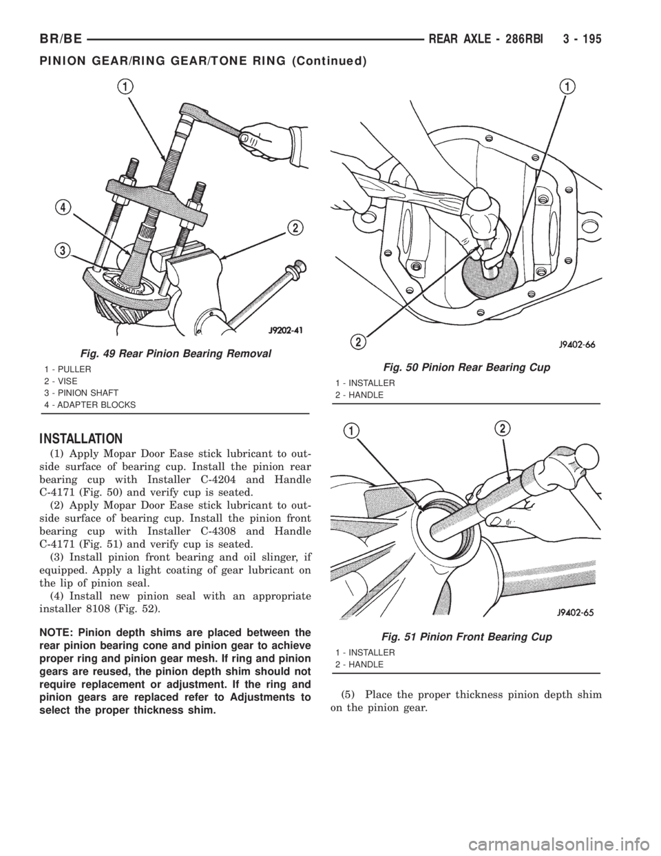
side surface of bearing cup. Install the pinion rear
bearing cup with Installer C-4204 and Handle
C-4171 (Fig. 50) and verify cup is seated.
(2) Apply Mopar Door Ease stick lubricant to out-
side surface of bearing cup. Install the pinion front
bearing cup with Installer C-4308 and Handle
C-4171 (Fig. 51) and verify cup is seated.
(3) Install pinion front bearing and oil slinger, if
equipped. Apply a light coating of gear lubricant on
the lip of pinion seal.
(4) Install new pinion seal with an appropriate
installer 8108 (Fig. 52).
NOTE: Pinion depth shims are placed between the
rear pinion bearing cone and pinion gear to achieve
proper ring and pinion gear mesh. If ring and pinion
gears are reused, the pinion depth shim should not
require replacement or adjustment. If the ring and
pinion gears are replaced refer to Adjustments to
select the proper thickness shim.(5) Place the proper thickness pinion depth shim
on the pinion gear.
Fig. 49 Rear Pinion Bearing Removal
1 - PULLER
2 - VISE
3 - PINION SHAFT
4 - ADAPTER BLOCKSFig. 50 Pinion Rear Bearing Cup
1 - INSTALLER
2 - HANDLE
Fig. 51 Pinion Front Bearing Cup
1 - INSTALLER
2 - HANDLE
BR/BEREAR AXLE - 286RBI 3 - 195
PINION GEAR/RING GEAR/TONE RING (Continued)
Page 310 of 2889
INSTALLATION - FRONT PARKING BRAKE
CABLE
(1) From inside the vehicle, insert the cable end
fitting into the hole in the pedal assembly.
(2) Seat the cable retainer in the pedal assembly.
(3) Engage the cable ball end in clevis on the pedal
assembly.
(4) Route the cable along the top of the wheel well
and clip in place.
(5) Route the cable through the floorpan and
install the body grommet.
(6) Place the carpet down and install the left cowl
trim and sill plate.
(7) Raise and support the vehicle.
(8) Route the cable through the underbody bracket
and seat the cable housing retainer in the bracket.
(9) Connect the cable to the cable connector.
(10) Perform the park brake adjustment proce-
dure, (Refer to 5 - BRAKES/PARKING BRAKE/CA-
BLE TENSIONER - ADJUSTMENTS).
(11) Lower the vehicle.
INSTALLATION - REAR PARK BRAKE CABLES -
1500 SERIES
(1) Install the parking brake cable guide spring.
(2) Install the brake drums.
(3) Pull back on the cable. Then push the cable
through the brake support plate hole to engage the
cable in the park brake lever.
NOTE: Pull on the cable end to ensure it is attached
to the park brake lever.
(4) Push each cable end through the brake support
plate hole until the cable end fitting tabs lock into
place.
NOTE: Pull on the cable to ensure it is locked into
place.
(5) Install the right cable retainers on the axle.
Route the right cable through the hole in the brake
hose bracket.
(6) Push both cables through the frame bracket.
NOTE: The right cable must be installed in the top
hole of the bracket.(7) Lock the left cable end fitting tabs into the
frame bracket lower hole.
(8) Install the right rear cable into the tensioner
cable bracket and lock the cable end fitting tabs into
place.
(9) Install the cables onto the cable connectors.
(10) Install the wheel and tire assemblies, (Refer
to 22 - TIRES/WHEELS/WHEELS - STANDARD
PROCEDURE).
(11) Perform the park brake adjustment procedure,
(Refer to 5 - BRAKES/PARKING BRAKE/CABLE
TENSIONER - ADJUSTMENTS).
(12) Remove the supports and lower the vehicle.
INSTALLATION - REAR PARK BRAKE CABLE
2500/3500 SERIES WITH DRUM BRAKES
(1) Install cable guide spring.
(2) Install the brake drums.
(3) Pull back on the cable. Then push the cable
through the brake support plate hole to engage the
cable in the park brake lever.
NOTE: Pull on the cable end to ensure it is attached
to the park brake lever.
(4) Push each cable housing through the brake
support plate hole until the cable end fitting tabs
lock into place.
NOTE: Pull on the cable housing to ensure it is
locked into place.
(5) Install the right cable retainers on the axle.
The push the right cable through the hole in the
brake hose bracket.
(6) Push both cables through the frame bracket.
Push the left cable until the cable end fitting tabs
lock into place. Install the O-ring on the right cable.
NOTE: The right cable must be installed in the top
hole of the bracket and left cable in the bottom
hole.
(7) Install the cables onto the cable tensioner
bracket and install the cables into the cable connec-
tors.
(8) Install the wheel and tire assemblies.
(9) Perform park brake adjustment procedure.
(10) Remove supports and lower vehicle.
BR/BEBRAKES 5 - 39
CABLES (Continued)
Page 1174 of 2889
(1) When refacing valve seats, it is important that
the correct size valve guide pilot be used for reseat-
ing stones. A true and complete surface must be
obtained.
(2) Measure the concentricity of valve seat using a
dial indicator. Total runout should not exceed 0.051
mm (0.002 in.) total indicator reading.
(3) Inspect the valve seat with Prussian blue, to
determine where the valve contacts the seat. To do
this, coat valve seat LIGHTLY with Prussian blue
then set valve in place. Rotate the valve with light
pressure. If the blue is transferred to the center of
valve face, contact is satisfactory. If the blue is trans-
ferred to the top edge of valve face, lower valve seat
with a 15É stone. If the blue is transferred to bottom
edge of valve face raise valve seat with a 60É stone.
(4) When seat is properly positioned the width of
intake seats should be 1.016-1.524 mm (0.040-0.060
in.). The width of the exhaust seats should be 1.524-
2.032 mm (0.060-0.080 in.).
VALVE SPRINGS
Whenever valves have been removed for inspection,
reconditioning or replacement, valve springs should
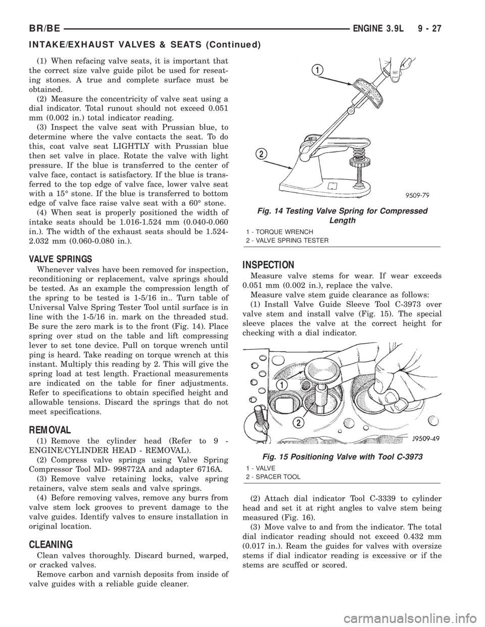
be tested. As an example the compression length of
the spring to be tested is 1-5/16 in.. Turn table of
Universal Valve Spring Tester Tool until surface is in
line with the 1-5/16 in. mark on the threaded stud.
Be sure the zero mark is to the front (Fig. 14). Place
spring over stud on the table and lift compressing
lever to set tone device. Pull on torque wrench until
ping is heard. Take reading on torque wrench at this
instant. Multiply this reading by 2. This will give the
spring load at test length. Fractional measurements
are indicated on the table for finer adjustments.
Refer to specifications to obtain specified height and
allowable tensions. Discard the springs that do not
meet specifications.
REMOVAL
(1) Remove the cylinder head (Refer to 9 -
ENGINE/CYLINDER HEAD - REMOVAL).
(2) Compress valve springs using Valve Spring
Compressor Tool MD- 998772A and adapter 6716A.
(3) Remove valve retaining locks, valve spring
retainers, valve stem seals and valve springs.
(4) Before removing valves, remove any burrs from
valve stem lock grooves to prevent damage to the
valve guides. Identify valves to ensure installation in
original location.
CLEANING
Clean valves thoroughly. Discard burned, warped,
or cracked valves.
Remove carbon and varnish deposits from inside of
valve guides with a reliable guide cleaner.
INSPECTION
Measure valve stems for wear. If wear exceeds
0.051 mm (0.002 in.), replace the valve.
Measure valve stem guide clearance as follows:
(1) Install Valve Guide Sleeve Tool C-3973 over
valve stem and install valve (Fig. 15). The special
sleeve places the valve at the correct height for
checking with a dial indicator.
(2) Attach dial indicator Tool C-3339 to cylinder
head and set it at right angles to valve stem being
measured (Fig. 16).
(3) Move valve to and from the indicator. The total
dial indicator reading should not exceed 0.432 mm
(0.017 in.). Ream the guides for valves with oversize
stems if dial indicator reading is excessive or if the
stems are scuffed or scored.
Fig. 14 Testing Valve Spring for Compressed
Length
1 - TORQUE WRENCH
2 - VALVE SPRING TESTER
Fig. 15 Positioning Valve with Tool C-3973
1 - VALVE
2 - SPACER TOOL
BR/BEENGINE 3.9L 9 - 27
INTAKE/EXHAUST VALVES & SEATS (Continued)
Page 1231 of 2889
(1) When refacing valve seats, it is important that
the correct size valve guide pilot be used for reseat-
ing stones. A true and complete surface must be
obtained.
(2) Measure the concentricity of valve seat using a
dial indicator. Total runout should not exceed 0.051
mm (0.002 in.) total indicator reading.
(3) Inspect the valve seat with Prussian blue, to
determine where the valve contacts the seat. To do
this, coat valve seat LIGHTLY with Prussian blue
then set valve in place. Rotate the valve with light
pressure. If the blue is transferred to the center of
valve face, contact is satisfactory. If the blue is trans-
ferred to the top edge of valve face, lower valve seat
with a 15É stone. If the blue is transferred to bottom
edge of valve face raise valve seat with a 60É stone.
(4) When seat is properly positioned the width of
intake seats should be 1.016-1.524 mm (0.040-0.060
in.). The width of the exhaust seats should be 1.524-
2.032 mm (0.060-0.080 in.).
VALVE SPRINGS
Whenever valves have been removed for inspection,
reconditioning or replacement, valve springs should
be tested. As an example the compression length of
the spring to be tested is 1-5/16 in.. Turn table of
Universal Valve Spring Tester Tool until surface is in
line with the 1-5/16 in. mark on the threaded stud.
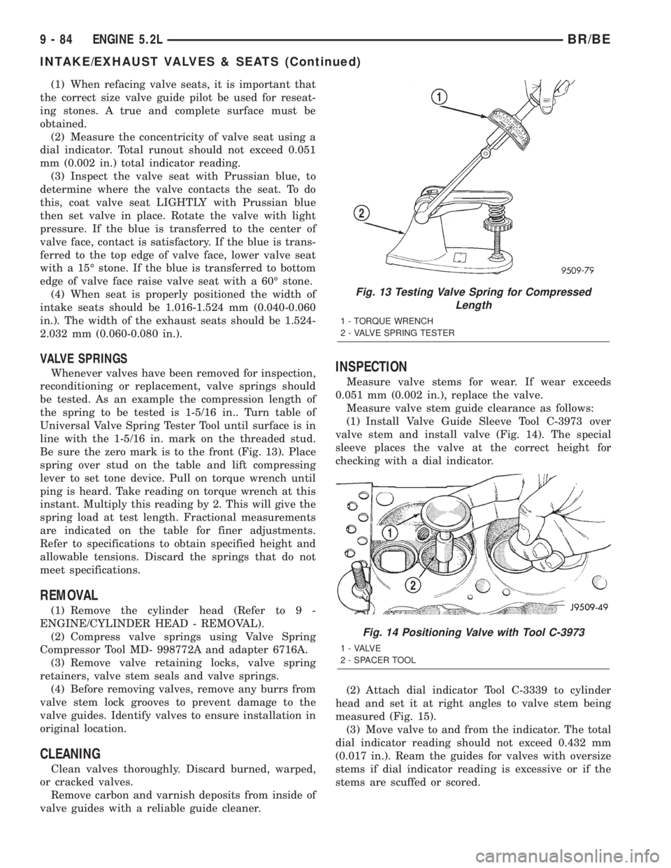
Be sure the zero mark is to the front (Fig. 13). Place
spring over stud on the table and lift compressing
lever to set tone device. Pull on torque wrench until
ping is heard. Take reading on torque wrench at this
instant. Multiply this reading by 2. This will give the
spring load at test length. Fractional measurements
are indicated on the table for finer adjustments.
Refer to specifications to obtain specified height and
allowable tensions. Discard the springs that do not
meet specifications.
REMOVAL
(1) Remove the cylinder head (Refer to 9 -
ENGINE/CYLINDER HEAD - REMOVAL).
(2) Compress valve springs using Valve Spring
Compressor Tool MD- 998772A and adapter 6716A.
(3) Remove valve retaining locks, valve spring
retainers, valve stem seals and valve springs.
(4) Before removing valves, remove any burrs from
valve stem lock grooves to prevent damage to the
valve guides. Identify valves to ensure installation in
original location.
CLEANING
Clean valves thoroughly. Discard burned, warped,
or cracked valves.
Remove carbon and varnish deposits from inside of
valve guides with a reliable guide cleaner.
INSPECTION
Measure valve stems for wear. If wear exceeds
0.051 mm (0.002 in.), replace the valve.
Measure valve stem guide clearance as follows:
(1) Install Valve Guide Sleeve Tool C-3973 over
valve stem and install valve (Fig. 14). The special
sleeve places the valve at the correct height for
checking with a dial indicator.
(2) Attach dial indicator Tool C-3339 to cylinder
head and set it at right angles to valve stem being
measured (Fig. 15).
(3) Move valve to and from the indicator. The total
dial indicator reading should not exceed 0.432 mm
(0.017 in.). Ream the guides for valves with oversize
stems if dial indicator reading is excessive or if the
stems are scuffed or scored.
Fig. 13 Testing Valve Spring for Compressed
Length
1 - TORQUE WRENCH
2 - VALVE SPRING TESTER
Fig. 14 Positioning Valve with Tool C-3973
1 - VALVE
2 - SPACER TOOL
9 - 84 ENGINE 5.2LBR/BE
INTAKE/EXHAUST VALVES & SEATS (Continued)
Page 1287 of 2889
VALVES
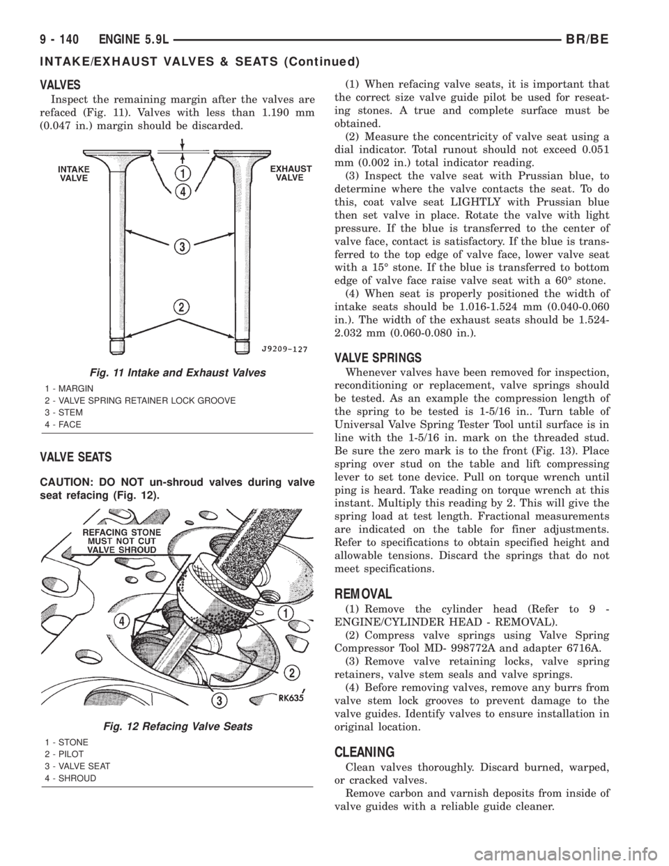
Inspect the remaining margin after the valves are
refaced (Fig. 11). Valves with less than 1.190 mm
(0.047 in.) margin should be discarded.
VALVE SEATS
CAUTION: DO NOT un-shroud valves during valve
seat refacing (Fig. 12).(1) When refacing valve seats, it is important that
the correct size valve guide pilot be used for reseat-
ing stones. A true and complete surface must be
obtained.
(2) Measure the concentricity of valve seat using a
dial indicator. Total runout should not exceed 0.051
mm (0.002 in.) total indicator reading.
(3) Inspect the valve seat with Prussian blue, to
determine where the valve contacts the seat. To do
this, coat valve seat LIGHTLY with Prussian blue
then set valve in place. Rotate the valve with light
pressure. If the blue is transferred to the center of
valve face, contact is satisfactory. If the blue is trans-
ferred to the top edge of valve face, lower valve seat
with a 15É stone. If the blue is transferred to bottom
edge of valve face raise valve seat with a 60É stone.
(4) When seat is properly positioned the width of
intake seats should be 1.016-1.524 mm (0.040-0.060
in.). The width of the exhaust seats should be 1.524-
2.032 mm (0.060-0.080 in.).
VALVE SPRINGS
Whenever valves have been removed for inspection,
reconditioning or replacement, valve springs should
be tested. As an example the compression length of
the spring to be tested is 1-5/16 in.. Turn table of
Universal Valve Spring Tester Tool until surface is in
line with the 1-5/16 in. mark on the threaded stud.
Be sure the zero mark is to the front (Fig. 13). Place
spring over stud on the table and lift compressing
lever to set tone device. Pull on torque wrench until
ping is heard. Take reading on torque wrench at this
instant. Multiply this reading by 2. This will give the
spring load at test length. Fractional measurements
are indicated on the table for finer adjustments.
Refer to specifications to obtain specified height and
allowable tensions. Discard the springs that do not
meet specifications.
REMOVAL
(1) Remove the cylinder head (Refer to 9 -
ENGINE/CYLINDER HEAD - REMOVAL).
(2) Compress valve springs using Valve Spring
Compressor Tool MD- 998772A and adapter 6716A.
(3) Remove valve retaining locks, valve spring
retainers, valve stem seals and valve springs.
(4) Before removing valves, remove any burrs from
valve stem lock grooves to prevent damage to the
valve guides. Identify valves to ensure installation in
original location.
CLEANING
Clean valves thoroughly. Discard burned, warped,
or cracked valves.
Remove carbon and varnish deposits from inside of
valve guides with a reliable guide cleaner.
Fig. 11 Intake and Exhaust Valves
1 - MARGIN
2 - VALVE SPRING RETAINER LOCK GROOVE
3 - STEM
4-FACE
Fig. 12 Refacing Valve Seats
1-STONE
2 - PILOT
3 - VALVE SEAT
4 - SHROUD
9 - 140 ENGINE 5.9LBR/BE
INTAKE/EXHAUST VALVES & SEATS (Continued)
Page 1344 of 2889
(3) Inspect the valve seat with Prussian blue to
determine where the valve contacts the seat. To do
this, coat valve seat LIGHTLY with Prussian blue
then set valve in place. Rotate the valve with light
pressure. If the blue is transferred to the center of
valve face, contact is satisfactory. If the blue is trans-
ferred to the top edge of valve face, lower valve seat
with a 15É stone. If the blue is transferred to bottom
edge of valve face raise valve seat with a 60É stone.
(4) When seat is properly positioned the width of
valve seats should be 1.016-1.524 mm (0.040-0.060
inch).
VALVE SPRING INSPECTION
Whenever valves have been removed for inspection,
reconditioning or replacement, valve springs should
be tested. As an example the compression length of
the spring to be tested is 1-5/16 inch. Turn table of
Universal Valve Spring Tester Tool until surface is in
line with the 1-5/16 inch mark on the threaded stud.
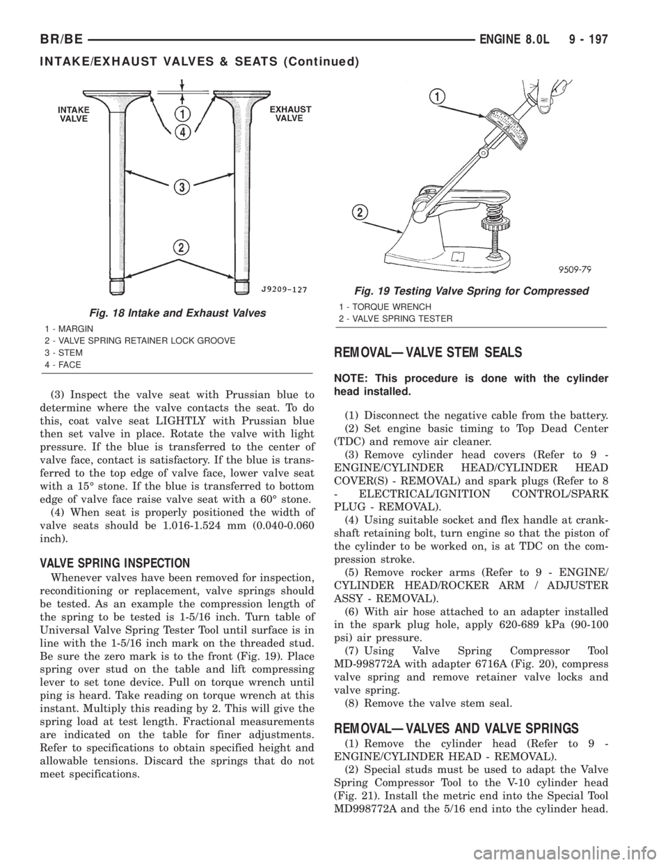
Be sure the zero mark is to the front (Fig. 19). Place
spring over stud on the table and lift compressing
lever to set tone device. Pull on torque wrench until
ping is heard. Take reading on torque wrench at this
instant. Multiply this reading by 2. This will give the
spring load at test length. Fractional measurements
are indicated on the table for finer adjustments.
Refer to specifications to obtain specified height and
allowable tensions. Discard the springs that do not
meet specifications.
REMOVALÐVALVE STEM SEALS
NOTE: This procedure is done with the cylinder
head installed.
(1) Disconnect the negative cable from the battery.
(2) Set engine basic timing to Top Dead Center
(TDC) and remove air cleaner.
(3) Remove cylinder head covers (Refer to 9 -
ENGINE/CYLINDER HEAD/CYLINDER HEAD
COVER(S) - REMOVAL) and spark plugs (Refer to 8
- ELECTRICAL/IGNITION CONTROL/SPARK
PLUG - REMOVAL).
(4) Using suitable socket and flex handle at crank-
shaft retaining bolt, turn engine so that the piston of
the cylinder to be worked on, is at TDC on the com-
pression stroke.
(5) Remove rocker arms (Refer to 9 - ENGINE/
CYLINDER HEAD/ROCKER ARM / ADJUSTER
ASSY - REMOVAL).
(6) With air hose attached to an adapter installed
in the spark plug hole, apply 620-689 kPa (90-100
psi) air pressure.
(7) Using Valve Spring Compressor Tool
MD-998772A with adapter 6716A (Fig. 20), compress
valve spring and remove retainer valve locks and
valve spring.
(8) Remove the valve stem seal.
REMOVALÐVALVES AND VALVE SPRINGS
(1) Remove the cylinder head (Refer to 9 -
ENGINE/CYLINDER HEAD - REMOVAL).
(2) Special studs must be used to adapt the Valve
Spring Compressor Tool to the V-10 cylinder head
(Fig. 21). Install the metric end into the Special Tool
MD998772A and the 5/16 end into the cylinder head.
Fig. 18 Intake and Exhaust Valves
1 - MARGIN
2 - VALVE SPRING RETAINER LOCK GROOVE
3 - STEM
4-FACE
Fig. 19 Testing Valve Spring for Compressed
1 - TORQUE WRENCH
2 - VALVE SPRING TESTER
BR/BEENGINE 8.0L 9 - 197
INTAKE/EXHAUST VALVES & SEATS (Continued)
Page 1376 of 2889
ENGINE 5.9L DIESEL
TABLE OF CONTENTS
page page
ENGINE 5.9L DIESEL
DESCRIPTION..........................231
DIAGNOSIS AND TESTING................232
ENGINE DIAGNOSIS - MECHANICAL.......232
SMOKE DIAGNOSIS CHARTS............234
STANDARD PROCEDURE.................237
FORM-IN-PLACE GASKETS AND SEALERS . . 237
REPAIR DAMAGED OR WORN THREADS . . . 238
HYDROSTATIC LOCK...................238
REMOVAL.............................238
INSTALLATION..........................241
SPECIFICATIONS........................242
SPECIAL TOOLS........................244
ENGINE DATA PLATE
DESCRIPTION..........................244
AIR CLEANER ELEMENT
REMOVAL.............................244
INSTALLATION..........................245
CYLINDER HEAD
DESCRIPTION..........................246
REMOVAL.............................246
CLEANING.............................248
INSPECTION...........................250
INSTALLATION..........................250
CYLINDER HEAD COVER(S)
REMOVAL.............................253
CLEANING.............................253
INSPECTION...........................253
INSTALLATION..........................253
INTAKE/EXHAUST VALVES & SEATS
DESCRIPTION..........................253
STANDARD PROCEDURE.................253
VALVES, GUIDES AND SPRINGS..........253
VALVE LASH ADJUSTMENT AND
VERIFICATION........................256
REMOVAL.............................258
INSTALLATION..........................260
ROCKER ARM / ADJUSTER ASSY
DESCRIPTION..........................261
REMOVAL.............................261
CLEANING.............................262
INSPECTION...........................262
INSTALLATION..........................263
ENGINE BLOCK
STANDARD PROCEDURE.................263
CYLINDER BORE REFACING.............263
CYLINDER BORE DE-GLAZE.............264
CYLINDER BORE REPAIR...............265
CAM BORE REPAIR....................267INSPECTION...........................267
CAMSHAFT & BEARINGS (IN BLOCK)
REMOVAL.............................268
INSPECTION...........................272
INSTALLATION..........................273
CONNECTING ROD BEARINGS
STANDARD PROCEDURE.................274
CONNECTING ROD BEARING AND
CRANKSHAFT JOURNAL CLEARANCE......274
CRANKSHAFT
DESCRIPTION..........................275
CRANKSHAFT MAIN BEARINGS
STANDARD PROCEDURE.................275
MAIN BEARING CLEARANCE............275
CRANKSHAFT OIL SEAL - FRONT
REMOVAL.............................276
INSTALLATION..........................277
CRANKSHAFT OIL SEAL - REAR
REMOVAL.............................278
INSTALLATION..........................278
CRANKSHAFT REAR OIL SEAL RETAINER
REMOVAL.............................278
INSTALLATION..........................279
SOLID LIFTERS/TAPPETS
REMOVAL.............................280
CLEANING.............................281
INSPECTION...........................281
INSTALLATION..........................281
PISTON & CONNECTING ROD
DESCRIPTION..........................282
STANDARD PROCEDURE.................282
PISTON GRADING....................282
REMOVAL.............................285
CLEANING.............................285
INSPECTION...........................285
INSTALLATION..........................287
PISTON RINGS
STANDARD PROCEDURE.................288
PISTON RINGS - FITTING...............288
VIBRATION DAMPER
REMOVAL.............................289
INSPECTION...........................289
INSTALLATION..........................289
FRONT MOUNT
REMOVAL.............................290
INSTALLATION..........................290
REAR MOUNT
REMOVAL.............................291
INSTALLATION..........................291
BR/BEENGINE 5.9L DIESEL 9 - 229