2001 CHRYSLER VOYAGER maintenance
[x] Cancel search: maintenancePage 1669 of 4284
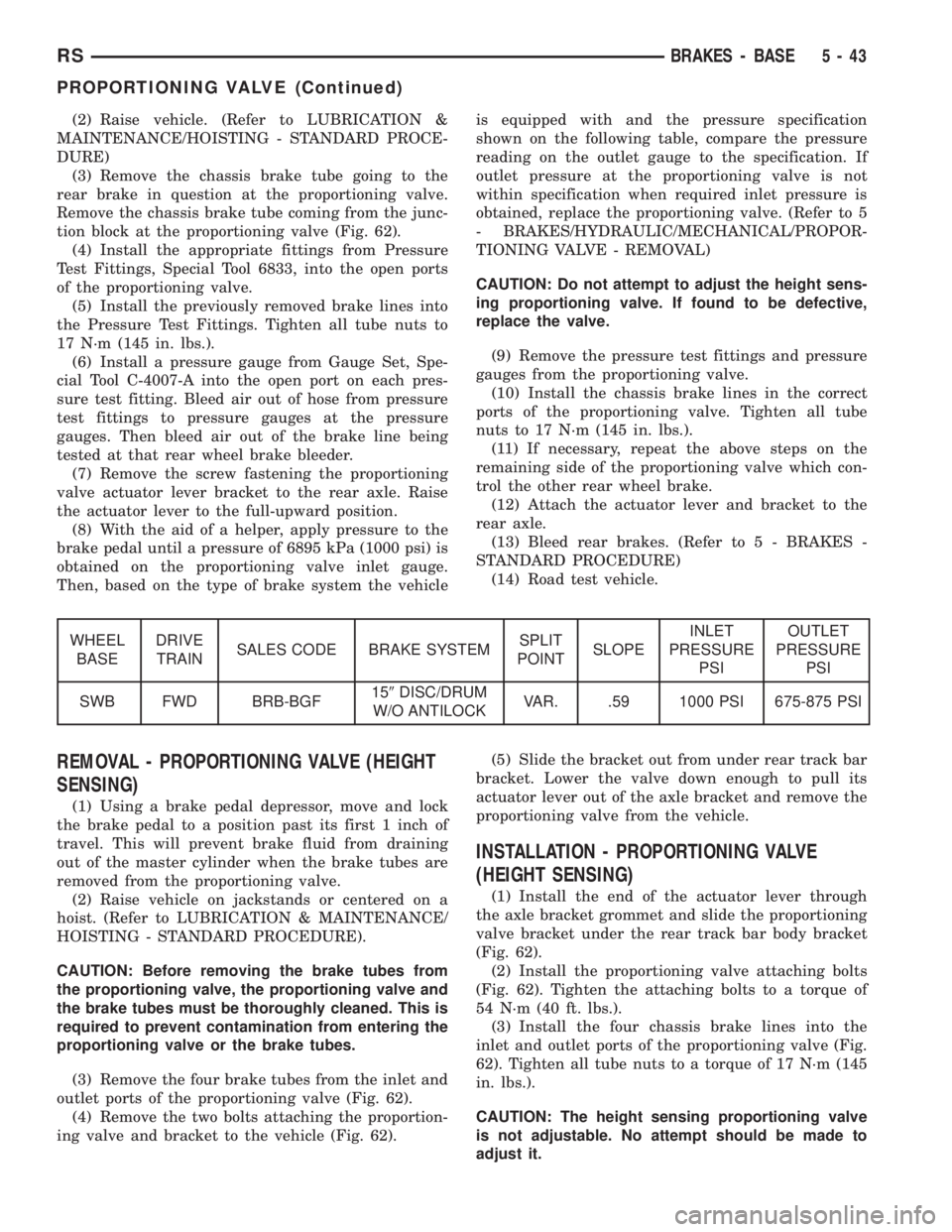
(2) Raise vehicle. (Refer to LUBRICATION &
MAINTENANCE/HOISTING - STANDARD PROCE-
DURE)
(3) Remove the chassis brake tube going to the
rear brake in question at the proportioning valve.
Remove the chassis brake tube coming from the junc-
tion block at the proportioning valve (Fig. 62).
(4) Install the appropriate fittings from Pressure
Test Fittings, Special Tool 6833, into the open ports
of the proportioning valve.
(5) Install the previously removed brake lines into
the Pressure Test Fittings. Tighten all tube nuts to
17 N´m (145 in. lbs.).
(6) Install a pressure gauge from Gauge Set, Spe-
cial Tool C-4007-A into the open port on each pres-
sure test fitting. Bleed air out of hose from pressure
test fittings to pressure gauges at the pressure
gauges. Then bleed air out of the brake line being
tested at that rear wheel brake bleeder.
(7) Remove the screw fastening the proportioning
valve actuator lever bracket to the rear axle. Raise
the actuator lever to the full-upward position.
(8) With the aid of a helper, apply pressure to the
brake pedal until a pressure of 6895 kPa (1000 psi) is
obtained on the proportioning valve inlet gauge.
Then, based on the type of brake system the vehicleis equipped with and the pressure specification
shown on the following table, compare the pressure
reading on the outlet gauge to the specification. If
outlet pressure at the proportioning valve is not
within specification when required inlet pressure is
obtained, replace the proportioning valve. (Refer to 5
- BRAKES/HYDRAULIC/MECHANICAL/PROPOR-
TIONING VALVE - REMOVAL)
CAUTION: Do not attempt to adjust the height sens-
ing proportioning valve. If found to be defective,
replace the valve.
(9) Remove the pressure test fittings and pressure
gauges from the proportioning valve.
(10) Install the chassis brake lines in the correct
ports of the proportioning valve. Tighten all tube
nuts to 17 N´m (145 in. lbs.).
(11) If necessary, repeat the above steps on the
remaining side of the proportioning valve which con-
trol the other rear wheel brake.
(12) Attach the actuator lever and bracket to the
rear axle.
(13) Bleed rear brakes. (Refer to 5 - BRAKES -
STANDARD PROCEDURE)
(14) Road test vehicle.
WHEEL
BASEDRIVE
TRAINSALES CODE BRAKE SYSTEMSPLIT
POINTSLOPEINLET
PRESSURE
PSIOUTLET
PRESSURE
PSI
SWB FWD BRB-BGF159DISC/DRUM
W/O ANTILOCKVAR. .59 1000 PSI 675-875 PSI
REMOVAL - PROPORTIONING VALVE (HEIGHT
SENSING)
(1) Using a brake pedal depressor, move and lock
the brake pedal to a position past its first 1 inch of
travel. This will prevent brake fluid from draining
out of the master cylinder when the brake tubes are
removed from the proportioning valve.
(2) Raise vehicle on jackstands or centered on a
hoist. (Refer to LUBRICATION & MAINTENANCE/
HOISTING - STANDARD PROCEDURE).
CAUTION: Before removing the brake tubes from
the proportioning valve, the proportioning valve and
the brake tubes must be thoroughly cleaned. This is
required to prevent contamination from entering the
proportioning valve or the brake tubes.
(3) Remove the four brake tubes from the inlet and
outlet ports of the proportioning valve (Fig. 62).
(4) Remove the two bolts attaching the proportion-
ing valve and bracket to the vehicle (Fig. 62).(5) Slide the bracket out from under rear track bar
bracket. Lower the valve down enough to pull its
actuator lever out of the axle bracket and remove the
proportioning valve from the vehicle.
INSTALLATION - PROPORTIONING VALVE
(HEIGHT SENSING)
(1) Install the end of the actuator lever through
the axle bracket grommet and slide the proportioning
valve bracket under the rear track bar body bracket
(Fig. 62).
(2) Install the proportioning valve attaching bolts
(Fig. 62). Tighten the attaching bolts to a torque of
54 N´m (40 ft. lbs.).
(3) Install the four chassis brake lines into the
inlet and outlet ports of the proportioning valve (Fig.
62). Tighten all tube nuts to a torque of 17 N´m (145
in. lbs.).
CAUTION: The height sensing proportioning valve
is not adjustable. No attempt should be made to
adjust it.
RSBRAKES - BASE5-43
PROPORTIONING VALVE (Continued)
Page 1674 of 4284
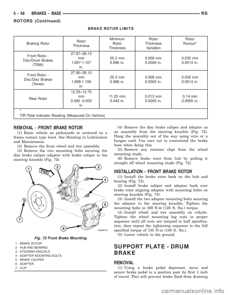
BRAKE ROTOR LIMITS
Braking RotorRotor
ThicknessMinimum
Rotor
ThicknessRotor
Thickness
VariationRotor
Runout*
Front Rotor -
Disc/Drum Brakes
(TRW)27.87±28.13
mm
1.097-1.107
in.25.3 mm
0.996 in.0.009 mm
0.0004 in.0.035 mm
0.0014 in.
Front Rotor -
Disc/Disc Brakes
(Teves)27.90±28.10
mm
1.098-1.106
in.25.3 mm
0.996 in.0.008 mm
0.0003 in.0.035 mm
0.0014 in.
Rear Rotor12.25±12.75
mm
0.482 -0.502
in.11.25 mm
0.443 in.0.013 mm
0.0005 in.0.14 mm
0.0055 in.
*
TIR Total Indicator Reading (Measured On Vehicle)
REMOVAL - FRONT BRAKE ROTOR
(1) Raise vehicle on jackstands or centered on a
frame contact type hoist. See Hoisting in Lubrication
and Maintenance.
(2) Remove the front wheel and tire assembly.
(3) Remove the two mounting bolts securing the
disc brake caliper adapter with brake caliper to the
steering knuckle (Fig. 72).(4) Remove the disc brake caliper and adapter as
an assembly from the steering knuckle (Fig. 72).
Hang the assembly out of the way using wire or a
bungee cord. Use care not to overextend the brake
hose when doing this.
(5) Remove any retainer clips from the wheel
mounting studs.
(6) Remove brake rotor from hub by pulling it
straight off wheel mounting studs (Fig. 72).
INSTALLATION - FRONT BRAKE ROTOR
(1) Install the brake rotor back on the hub and
bearing (Fig. 72).
(2) Install brake caliper and adapter back over
brake rotor aligning adapter with mounting holes on
steering knuckle (Fig. 72).
(3) Install the two adapter mounting bolts securing
the adapter to the steering knuckle. Tighten the
mounting bolts to 169 N´m (125 ft. lbs.) torque.
(4) Install wheel and tire assembly on vehicle.
Tighten the wheel mounting lug nuts in proper
sequence until all nuts are torqued to half specifica-
tion, then repeat the tightening sequence to the full
specified torque of 135 N´m (100 ft. lbs.).
(5) Lower vehicle to the ground.
SUPPORT PLATE - DRUM
BRAKE
REMOVAL
(1) Using a brake pedal depressor, move and
secure brake pedal to a position past its first 1 inch
of travel. This will prevent brake fluid from draining
Fig. 72 Front Brake Mounting
1 - BRAKE ROTOR
2 - HUB AND BEARING
3 - STEERING KNUCKLE
4 - ADAPTER MOUNTING BOLTS
5 - BRAKE CALIPER
6 - ADAPTER
7 - CLIP
5 - 48 BRAKES - BASERS
ROTORS (Continued)
Page 1675 of 4284
out of master cylinder when brake tube is remove
from wheel cylinder.
(2) Raise vehicle. (Refer to LUBRICATION &
MAINTENANCE/HOISTING - STANDARD PROCE-
DURE).
(3) Remove wheel and tire assembly.
(4) Disconnect brake tube from rear of wheel cylin-
der. Cap open ends
(5) Remove brake drum.
(6) Remove brake shoes from brake support plate.
(Refer to 5 - BRAKES/HYDRAULIC/MECHANICAL/
BRAKE PADS/SHOES - REMOVAL).
(7) Remove the 2 bolts attaching the wheel cylin-
der to the brake support plate.
(8) Remove the wheel cylinder from the brake sup-
port plate.
(9) Disconnect the park brake cable from the park
brake actuation lever.
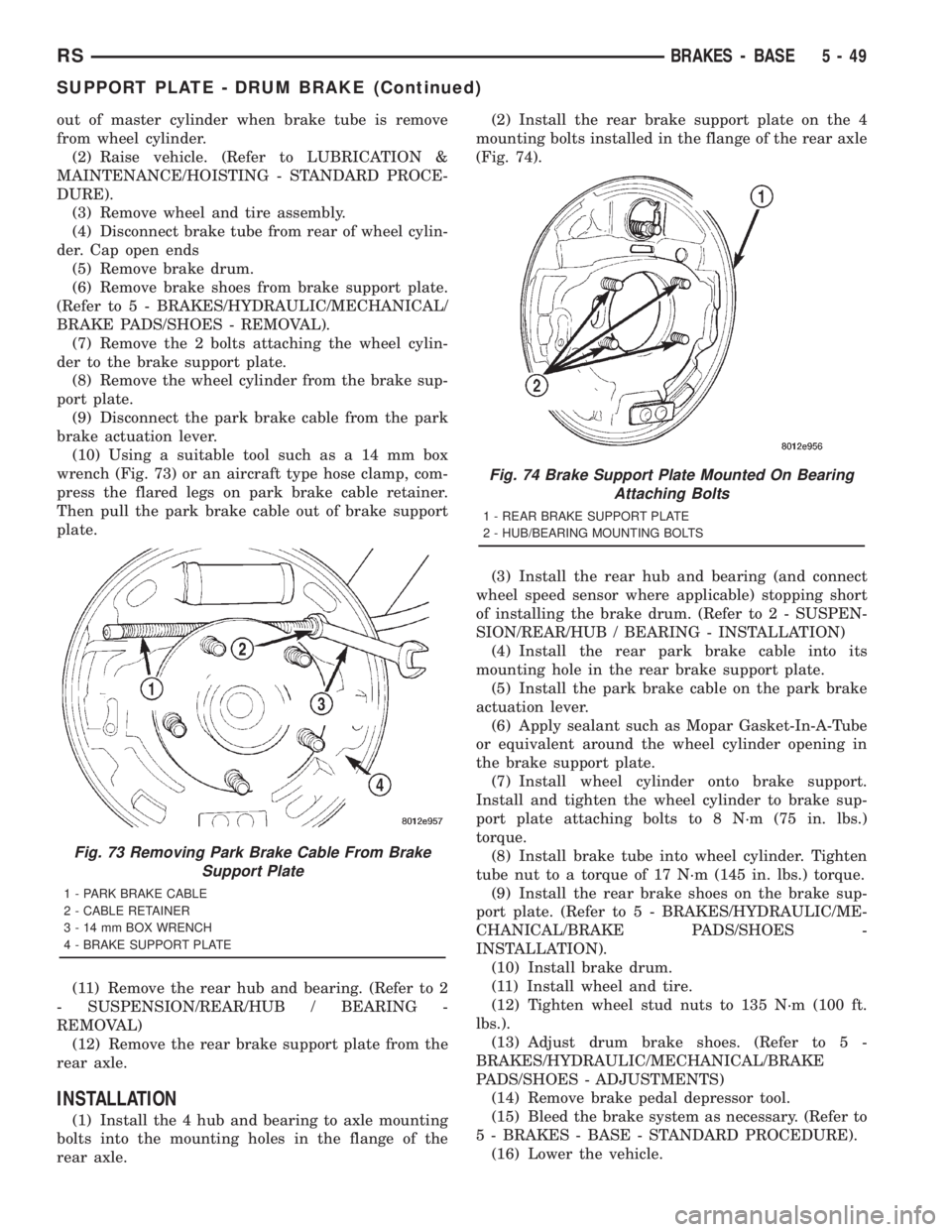
(10) Using a suitable tool such as a 14 mm box
wrench (Fig. 73) or an aircraft type hose clamp, com-
press the flared legs on park brake cable retainer.
Then pull the park brake cable out of brake support
plate.
(11) Remove the rear hub and bearing. (Refer to 2
- SUSPENSION/REAR/HUB / BEARING -
REMOVAL)
(12) Remove the rear brake support plate from the
rear axle.
INSTALLATION
(1) Install the 4 hub and bearing to axle mounting
bolts into the mounting holes in the flange of the
rear axle.(2) Install the rear brake support plate on the 4
mounting bolts installed in the flange of the rear axle
(Fig. 74).
(3) Install the rear hub and bearing (and connect
wheel speed sensor where applicable) stopping short
of installing the brake drum. (Refer to 2 - SUSPEN-
SION/REAR/HUB / BEARING - INSTALLATION)
(4) Install the rear park brake cable into its
mounting hole in the rear brake support plate.
(5) Install the park brake cable on the park brake
actuation lever.
(6) Apply sealant such as Mopar Gasket-In-A-Tube
or equivalent around the wheel cylinder opening in
the brake support plate.
(7) Install wheel cylinder onto brake support.
Install and tighten the wheel cylinder to brake sup-
port plate attaching bolts to 8 N´m (75 in. lbs.)
torque.
(8) Install brake tube into wheel cylinder. Tighten
tube nut to a torque of 17 N´m (145 in. lbs.) torque.
(9) Install the rear brake shoes on the brake sup-
port plate. (Refer to 5 - BRAKES/HYDRAULIC/ME-
CHANICAL/BRAKE PADS/SHOES -
INSTALLATION).
(10) Install brake drum.
(11) Install wheel and tire.
(12) Tighten wheel stud nuts to 135 N´m (100 ft.
lbs.).
(13) Adjust drum brake shoes. (Refer to 5 -
BRAKES/HYDRAULIC/MECHANICAL/BRAKE
PADS/SHOES - ADJUSTMENTS)
(14) Remove brake pedal depressor tool.
(15) Bleed the brake system as necessary. (Refer to
5 - BRAKES - BASE - STANDARD PROCEDURE).
(16) Lower the vehicle.
Fig. 73 Removing Park Brake Cable From Brake
Support Plate
1 - PARK BRAKE CABLE
2 - CABLE RETAINER
3 - 14 mm BOX WRENCH
4 - BRAKE SUPPORT PLATE
Fig. 74 Brake Support Plate Mounted On Bearing
Attaching Bolts
1 - REAR BRAKE SUPPORT PLATE
2 - HUB/BEARING MOUNTING BOLTS
RSBRAKES - BASE5-49
SUPPORT PLATE - DRUM BRAKE (Continued)
Page 1676 of 4284
WHEEL CYLINDERS
REMOVAL
(1) Using a brake pedal depressor, move and
secure brake pedal to a position past its first 1 inch
of travel. This will prevent brake fluid from draining
out of master cylinder when brake tube is remove
from wheel cylinder.
(2) Raise vehicle. (Refer to LUBRICATION &
MAINTENANCE/HOISTING - STANDARD PROCE-
DURE).
(3) Remove wheel and tire assembly.
(4) Disconnect brake tube from rear of wheel cylin-
der. Cap open ends
(5) Remove brake drum.
(6) Remove brake shoes from brake support plate
(Discard if contaminated).(Refer to 5 - BRAKES/HY-
DRAULIC/MECHANICAL/BRAKE PADS/SHOES -
REMOVAL)
(7) Remove the 2 bolts attaching the wheel cylin-
der to the brake support plate.
(8) Remove the wheel cylinder from the brake sup-
port plate.
INSPECTION
With brake drums removed, inspect the wheel cyl-
inder boots for evidence of a brake fluid leak. Visu-
ally check the boots for cuts, tears, or heat cracks. If
any of these conditions exist, the wheel cylinders
should be completely cleaned, inspected and new
parts installed.
If a wheel cylinder is leaking and the brake lining
material is saturated with brake fluid, the brake
shoes must be replaced.
INSTALLATION
(1) Apply sealant such as Mopar Gasket-In-A-Tube
or equivalent around the wheel cylinder opening in
the brake support plate.
(2) Install wheel cylinder onto brake support.
Install and tighten the wheel cylinder to brake sup-
port plate attaching bolts to 8 N´m (75 in. lbs.)
torque.
(3) Install brake tube into wheel cylinder. Tighten
tube nut to a torque of 17 N´m (145 in. lbs.) torque.
(4) Install the rear brake shoes on the brake sup-
port plate. (Refer to 5 - BRAKES/HYDRAULIC/ME-
CHANICAL/BRAKE PADS/SHOES -
INSTALLATION).
(5) Install brake drum.
(6) Install wheel and tire. Install and tighten
wheel lug nuts to 135 N´m (100 ft. lbs.).
(7) Adjust drum brake shoes. (Refer to 5 -
BRAKES/HYDRAULIC/MECHANICAL/BRAKE
PADS/SHOES - ADJUSTMENTS)
(8) Remove brake pedal depressor tool.(9) Bleed the brake system as necessary. (Refer to
5 - BRAKES - BASE - STANDARD PROCEDURE).
(10) Lower vehicle.
PARKING BRAKE
DESCRIPTION
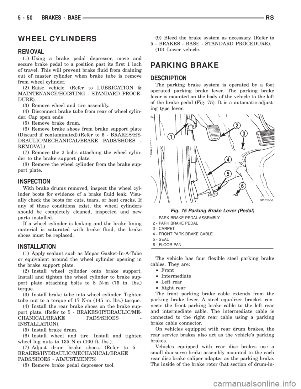
The parking brake system is operated by a foot
operated parking brake lever. The parking brake
lever is mounted on the body of the vehicle to the left
of the brake pedal (Fig. 75). It is a automatic-adjust-
ing type lever.
The vehicle has four flexible steel parking brake
cables. They are:
²Front
²Intermediate
²Left rear
²Right rear
The front parking brake cable extends from the
parking brake lever. A steel equalizer bracket con-
nects the front parking brake cable to the left rear
and intermediate cable. The intermediate cable is
connected to the right rear cable using a parking
brake cable connector.
On vehicles equipped with rear drum brakes, the
rear service brakes also act as the vehicle's parking
brakes.
Vehicles equipped with rear disc brakes use a
small duo-servo brake assembly mounted to the each
rear disc brake caliper adapter as the parking brake.
The inside of the brake rotor (hat section of drum-in-
Fig. 75 Parking Brake Lever (Pedal)
1 - PARK BRAKE PEDAL ASSEMBLY
2 - PARK BRAKE PEDAL
3 - CARPET
4 - FRONT PARK BRAKE CABLE
5 - SEAL
6 - FLOOR PAN
5 - 50 BRAKES - BASERS
Page 1679 of 4284
(14) Pull downward on front park brake cable
while rotating park brake pedal mechanism out from
behind junction block.
(15) Remove park brake pedal release link from
park brake mechanism.
(16) Remove the warning lamp ground switch con-
nector from the park brake pedal mechanism (Fig.
79).
(17) Remove front park brake cable button from
park brake pedal mechanism. Tap end housing for
front park brake cable out of park brake pedal mech-
anism.
INSTALLATION
(1) Install park brake cable end housing into park
brake pedal mechanism.
(2) Install cable retainer onto the park brake cable
strand and then install retainer into pedal bracket.
(3) Install cable strand button into the clevis on
the park brake pedal mechanism.
(4) Install wiring harness connector on warning
indicator lamp ground switch.
(5) Install the park brake release rod on the
release mechanism of the park brake pedal.
(6) Position the park brake pedal mechanism into
its installed position on the body of the vehicle.
(7) Loosely install the top bolt mounting the park
brake pedal mechanism to the body (Fig. 79).
(8) Loosely install the forward nut mounting the
park brake pedal mechanism to the body (Fig. 79).
(9) Loosely install the lower bolt mounting the
park brake pedal mechanism to the body (Fig. 79).
(10) Tighten pedal mechanism attaching bolts and
nut to 28 N´m (250 in. lbs.).
(11) Verify that the park brake pedal is in the fully
released (full up) position.
(12) Raise vehicle.
(13) Install the front park brake cable on the park
brake cable equalizer (Fig. 78).
NOTE: If the original lever assembly is being used,
the lever mechanism auto adjuster spring tension
will need to be reset. (Refer to 5 - BRAKES/PARK-
ING BRAKE - STANDARD PROCEDURE)
(14) Lower vehicle.
(15) Remove the lock-out pin (if a new lever has
been installed) from the automatic cable adjuster on
the park brake pedal mechanism.
(16) Install the electrical junction block on the
instrument panel.
(17) Install the reinforcement on the lower instru-
ment panel.
(18) Install the steering column lower cover on the
lower instrument panel.(19) Install the silencer panel under the instru-
ment panel.
(20) Install the left side kick panel.
(21) Install the sill scuff plate on the lower sill of
the left door.
(22) Install the negative (ground) cable on the bat-
tery.
(23) Cycle the park brake pedal one time. This will
seat the park brake cables and will allow the auto-
matic self adjuster to properly tension the park brake
cables.
SHOES - PARKING BRAKE
REMOVAL
(1) Set the parking brake.The parking brake is
set to keep the hub/bearing and axle shaft from
rotating when loosening the hub nut.
(2) Raise vehicle. (Refer to LUBRICATION &
MAINTENANCE/HOISTING - STANDARD PROCE-
DURE).
(3) Remove the wheel and tire assembly.
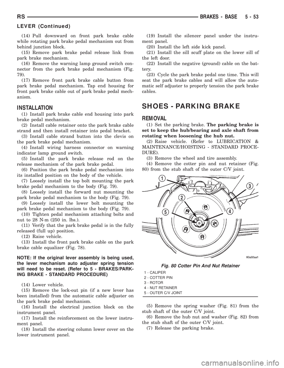
(4) Remove the cotter pin and nut retainer (Fig.
80) from the stub shaft of the outer C/V joint.
(5) Remove the spring washer (Fig. 81) from the
stub shaft of the outer C/V joint.
(6) Remove the hub nut and washer (Fig. 82) from
the stub shaft of the outer C/V joint.
(7) Release the parking brake.
Fig. 80 Cotter Pin And Nut Retainer
1 - CALIPER
2 - COTTER PIN
3 - ROTOR
4 - NUT RETAINER
5 - OUTER C/V JOINT
RSBRAKES - BASE5-53
LEVER (Continued)
Page 1687 of 4284
(18) Road test the vehicle to ensure proper func-
tion of the vehicle's brake system.
CABLES - PARKING BRAKE
REMOVAL - PARKING BRAKE CABLE (FRONT)
(1) Raise vehicle on jackstands or centered on a
hoist. (Refer to LUBRICATION & MAINTENANCE/
HOISTING - STANDARD PROCEDURE).
(2) Manually release the automatic self-adjusting
mechanism tension of the parking brake lever (pedal)
assembly. (Refer to 5 - BRAKES - STANDARD PRO-
CEDURE).
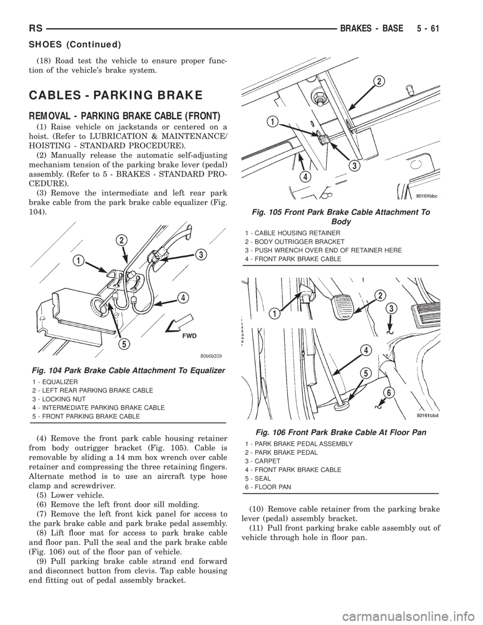
(3) Remove the intermediate and left rear park
brake cable from the park brake cable equalizer (Fig.
104).
(4) Remove the front park cable housing retainer
from body outrigger bracket (Fig. 105). Cable is
removable by sliding a 14 mm box wrench over cable
retainer and compressing the three retaining fingers.
Alternate method is to use an aircraft type hose
clamp and screwdriver.
(5) Lower vehicle.
(6) Remove the left front door sill molding.
(7) Remove the left front kick panel for access to
the park brake cable and park brake pedal assembly.
(8) Lift floor mat for access to park brake cable
and floor pan. Pull the seal and the park brake cable
(Fig. 106) out of the floor pan of vehicle.
(9) Pull parking brake cable strand end forward
and disconnect button from clevis. Tap cable housing
end fitting out of pedal assembly bracket.(10) Remove cable retainer from the parking brake
lever (pedal) assembly bracket.
(11) Pull front parking brake cable assembly out of
vehicle through hole in floor pan.
Fig. 104 Park Brake Cable Attachment To Equalizer
1 - EQUALIZER
2 - LEFT REAR PARKING BRAKE CABLE
3 - LOCKING NUT
4 - INTERMEDIATE PARKING BRAKE CABLE
5 - FRONT PARKING BRAKE CABLE
Fig. 105 Front Park Brake Cable Attachment To
Body
1 - CABLE HOUSING RETAINER
2 - BODY OUTRIGGER BRACKET
3 - PUSH WRENCH OVER END OF RETAINER HERE
4 - FRONT PARK BRAKE CABLE
Fig. 106 Front Park Brake Cable At Floor Pan
1 - PARK BRAKE PEDAL ASSEMBLY
2 - PARK BRAKE PEDAL
3 - CARPET
4 - FRONT PARK BRAKE CABLE
5 - SEAL
6 - FLOOR PAN
RSBRAKES - BASE5-61
SHOES (Continued)
Page 1688 of 4284
REMOVAL - PARKING BRAKE CABLE
(INTERMEDIATE)
(1) Raise the vehicle. (Refer to LUBRICATION &
MAINTENANCE/HOISTING - STANDARD PROCE-
DURE).
(2) Manually lock out the automatic self-adjusting
mechanism tension of the parking brake lever (pedal)
assembly. (Refer to 5 - BRAKES - STANDARD PRO-
CEDURE). Once the cable is released from the equal-
izer, do not remove the locking pliers until
reinstallation of the cable is complete.
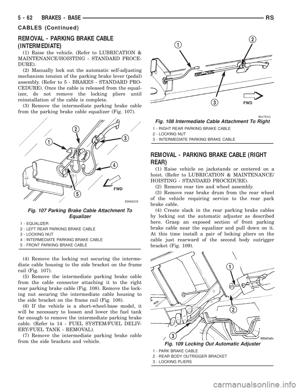
(3) Remove the intermediate parking brake cable
from the parking brake cable equalizer (Fig. 107).
(4) Remove the locking nut securing the interme-
diate cable housing to the side bracket on the frame
rail (Fig. 107).
(5) Remove the intermediate parking brake cable
from the cable connector attaching it to the right
rear parking brake cable (Fig. 108). Remove the lock-
ing nut securing the intermediate cable housing to
the side bracket on the frame rail (Fig. 108).
(6) If the vehicle is a short-wheel-base model, it
will be necessary to loosen and lower the fuel tank
far enough to remove the intermediate parking brake
cable. (Refer to 14 - FUEL SYSTEM/FUEL DELIV-
ERY/FUEL TANK - REMOVAL).
(7) Remove the intermediate parking brake cable
from the side brackets and vehicle.
REMOVAL - PARKING BRAKE CABLE (RIGHT
REAR)
(1) Raise vehicle on jackstands or centered on a
hoist. (Refer to LUBRICATION & MAINTENANCE/
HOISTING - STANDARD PROCEDURE).
(2) Remove rear tire and wheel assembly.
(3) Remove rear brake drum from the rear wheel
of the vehicle requiring service to the rear park
brake cable.
(4) Create slack in the rear parking brake cables
by locking out the automatic adjuster as described
here. Grasp an exposed section of front parking
brake cable near the equalizer and pull down on it.
At this time install a pair of locking pliers on the
cable just rearward of the second body outrigger
bracket (Fig. 109).
Fig. 107 Parking Brake Cable Attachment To
Equalizer
1 - EQUALIZER
2 - LEFT REAR PARKING BRAKE CABLE
3 - LOCKING NUT
4 - INTERMEDIATE PARKING BRAKE CABLE
5 - FRONT PARKING BRAKE CABLE
Fig. 108 Intermediate Cable Attachment To Right
1 - RIGHT REAR PARKING BRAKE CABLE
2 - LOCKING NUT
3 - INTERMEDIATE PARKING BRAKE CABLE
Fig. 109 Locking Out Automatic Adjuster
1 - PARK BRAKE CABLE
2 - REAR BODY OUTRIGGER BRACKET
3 - LOCKING PLIERS
5 - 62 BRAKES - BASERS
CABLES (Continued)
Page 1689 of 4284
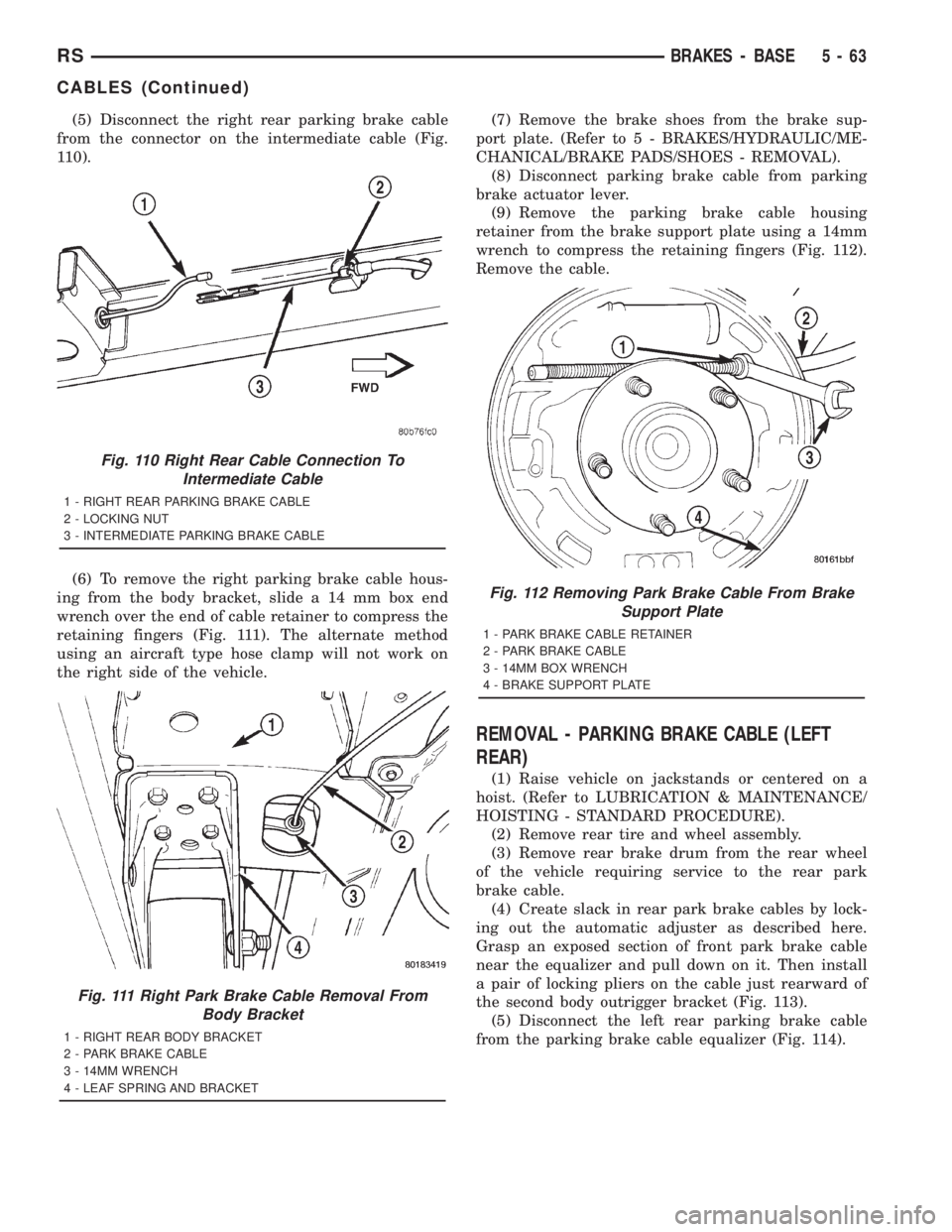
(5) Disconnect the right rear parking brake cable
from the connector on the intermediate cable (Fig.
110).
(6) To remove the right parking brake cable hous-
ing from the body bracket, slide a 14 mm box end
wrench over the end of cable retainer to compress the
retaining fingers (Fig. 111). The alternate method
using an aircraft type hose clamp will not work on
the right side of the vehicle.(7) Remove the brake shoes from the brake sup-
port plate. (Refer to 5 - BRAKES/HYDRAULIC/ME-
CHANICAL/BRAKE PADS/SHOES - REMOVAL).
(8) Disconnect parking brake cable from parking
brake actuator lever.
(9) Remove the parking brake cable housing
retainer from the brake support plate using a 14mm
wrench to compress the retaining fingers (Fig. 112).
Remove the cable.
REMOVAL - PARKING BRAKE CABLE (LEFT
REAR)
(1) Raise vehicle on jackstands or centered on a
hoist. (Refer to LUBRICATION & MAINTENANCE/
HOISTING - STANDARD PROCEDURE).
(2) Remove rear tire and wheel assembly.
(3) Remove rear brake drum from the rear wheel
of the vehicle requiring service to the rear park
brake cable.
(4) Create slack in rear park brake cables by lock-
ing out the automatic adjuster as described here.
Grasp an exposed section of front park brake cable
near the equalizer and pull down on it. Then install
a pair of locking pliers on the cable just rearward of
the second body outrigger bracket (Fig. 113).
(5) Disconnect the left rear parking brake cable
from the parking brake cable equalizer (Fig. 114).
Fig. 110 Right Rear Cable Connection To
Intermediate Cable
1 - RIGHT REAR PARKING BRAKE CABLE
2 - LOCKING NUT
3 - INTERMEDIATE PARKING BRAKE CABLE
Fig. 111 Right Park Brake Cable Removal From
Body Bracket
1 - RIGHT REAR BODY BRACKET
2 - PARK BRAKE CABLE
3 - 14MM WRENCH
4 - LEAF SPRING AND BRACKET
Fig. 112 Removing Park Brake Cable From Brake
Support Plate
1 - PARK BRAKE CABLE RETAINER
2 - PARK BRAKE CABLE
3 - 14MM BOX WRENCH
4 - BRAKE SUPPORT PLATE
RSBRAKES - BASE5-63
CABLES (Continued)