2001 CHRYSLER VOYAGER maintenance
[x] Cancel search: maintenancePage 1856 of 4284
BATTERY SYSTEM
DESCRIPTION
A single 12-volt battery system is standard factory-
installed equipment on this model. All of the compo-
nents of the battery system are located within the
engine compartment of the vehicle. The service infor-
mation for the battery system in this vehicle covers
the following related components, which are covered
in further detail elsewhere in this service manual:
²Battery- The storage battery provides a reli-
able means of storing a renewable source of electrical
energy within the vehicle.
²Battery Cable- The battery cables connect the
battery terminal posts to the vehicle electrical sys-
tem.
²Battery Holddown- The battery holddown
hardware secures the battery in the battery tray in
the engine compartment.
²Battery Thermoguard- The battery thermo-
guard insulates the battery to protect it from engine
compartment temperature extremes.
²Battery Tray- The battery tray provides a
secure mounting location in the vehicle for the bat-
tery and an anchor point for the battery holddown
hardware.
For battery system maintenance schedules and
jump starting procedures, see the owner's manual in
the vehicle glove box. Optionally, refer to Lubrication
and Maintanance for the recommended battery main-
tenance schedules and for the proper battery jump
starting procedures. While battery charging can be
considered a maintenance procedure, the battery
charging procedures and related information are
located in the standard procedures section of this ser-
vice manual. This was done because the battery must
be fully-charged before any battery system diagnosis
or testing procedures can be performed. Refer to
Standard procedures for the proper battery charging
procedures.
OPERATION
The battery system is designed to provide a safe,
efficient, reliable and mobile means of delivering and
storing electrical energy. This electrical energy is
required to operate the engine starting system, as
well as to operate many of the other vehicle acces-sory systems for limited durations while the engine
and/or the charging system are not operating. The
battery system is also designed to provide a reserve
of electrical energy to supplement the charging sys-
tem for short durations while the engine is running
and the electrical current demands of the vehicle
exceed the output of the charging system. In addition
to delivering, and storing electrical energy for the
vehicle, the battery system serves as a capacitor and
voltage stabilizer for the vehicle electrical system. It
absorbs most abnormal or transient voltages caused
by the switching of any of the electrical components
or circuits in the vehicle.
DIAGNOSIS AND TESTING - BATTERY SYSTEM
The battery, starting, and charging systems in the
vehicle operate with one another and must be tested
as a single complete system. In order for the engine
to start and the battery to charge properly, all of the
components that are used in these systems must per-
form within specifications. It is important that the
battery, starting, and charging systems be thoroughly
tested and inspected any time a battery needs to be
charged or replaced. The cause of abnormal battery
discharge, overcharging or early battery failure must
be diagnosed and corrected before a battery is
replaced and before a vehicle is returned to service.
The service information for these systems has been
separated within this service manual to make it eas-
ier to locate the specific information you are seeking.
However, when attempting to diagnose any of these
systems, it is important that you keep their interde-
pendency in mind.
The diagnostic procedures used for the battery,
starting, and charging systems include the most
basic conventional diagnostic methods, to the more
sophisticated On-Board Diagnostics (OBD) built into
the Powertrain Control Module (PCM). Use of an
induction-type milliampere ammeter, a volt/ohmme-
ter, a battery charger, a carbon pile rheostat (load
tester) and a 12-volt test lamp may be required. All
OBD-sensed systems are monitored by the PCM.
Each monitored circuit is assigned a Diagnostic Trou-
ble Code (DTC). The PCM will store a DTC in elec-
tronic memory for any failure it detects. Refer to
Charging System for the proper charging system on-
board diagnostic test procedures.
8F - 2 BATTERY SYSTEMRS
Page 1859 of 4284
²A faulty or incorrect starting system component.
Refer to Starting System for the proper starting sys-
tem diagnosis and testing procedures.
²A faulty or incorrect battery. Refer to Standard
Procedures for the proper battery diagnosis and test-
ing procedures. Refer to Battery System Specifica-
tions for the proper specifications.
CLEANING
The following information details the recommended
cleaning procedures for the battery and related com-
ponents. In addition to the maintenance schedules
found in this service manual and the owner's man-
ual, it is recommended that these procedures be per-
formed any time the battery or related components
must be removed for vehicle service.
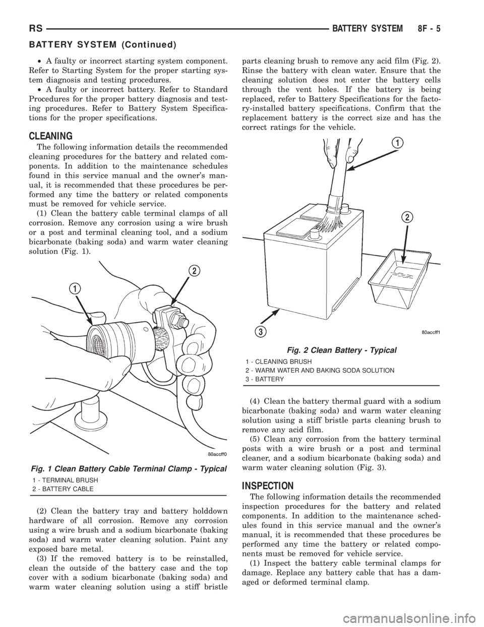
(1) Clean the battery cable terminal clamps of all
corrosion. Remove any corrosion using a wire brush
or a post and terminal cleaning tool, and a sodium
bicarbonate (baking soda) and warm water cleaning
solution (Fig. 1).
(2) Clean the battery tray and battery holddown
hardware of all corrosion. Remove any corrosion
using a wire brush and a sodium bicarbonate (baking
soda) and warm water cleaning solution. Paint any
exposed bare metal.
(3) If the removed battery is to be reinstalled,
clean the outside of the battery case and the top
cover with a sodium bicarbonate (baking soda) and
warm water cleaning solution using a stiff bristleparts cleaning brush to remove any acid film (Fig. 2).
Rinse the battery with clean water. Ensure that the
cleaning solution does not enter the battery cells
through the vent holes. If the battery is being
replaced, refer to Battery Specifications for the facto-
ry-installed battery specifications. Confirm that the
replacement battery is the correct size and has the
correct ratings for the vehicle.
(4) Clean the battery thermal guard with a sodium
bicarbonate (baking soda) and warm water cleaning
solution using a stiff bristle parts cleaning brush to
remove any acid film.
(5) Clean any corrosion from the battery terminal
posts with a wire brush or a post and terminal
cleaner, and a sodium bicarbonate (baking soda) and
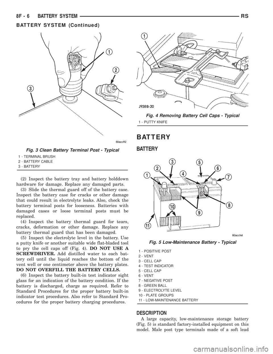
warm water cleaning solution (Fig. 3).
INSPECTION
The following information details the recommended
inspection procedures for the battery and related
components. In addition to the maintenance sched-
ules found in this service manual and the owner's
manual, it is recommended that these procedures be
performed any time the battery or related compo-
nents must be removed for vehicle service.
(1) Inspect the battery cable terminal clamps for
damage. Replace any battery cable that has a dam-
aged or deformed terminal clamp.
Fig. 1 Clean Battery Cable Terminal Clamp - Typical
1 - TERMINAL BRUSH
2 - BATTERY CABLE
Fig. 2 Clean Battery - Typical
1 - CLEANING BRUSH
2 - WARM WATER AND BAKING SODA SOLUTION
3 - BATTERY
RSBATTERY SYSTEM8F-5
BATTERY SYSTEM (Continued)
Page 1860 of 4284
(2) Inspect the battery tray and battery holddown
hardware for damage. Replace any damaged parts.
(3) Slide the thermal guard off of the battery case.
Inspect the battery case for cracks or other damage
that could result in electrolyte leaks. Also, check the
battery terminal posts for looseness. Batteries with
damaged cases or loose terminal posts must be
replaced.
(4) Inspect the battery thermal guard for tears,
cracks, deformation or other damage. Replace any
battery thermal guard that has been damaged.
(5) Inspect the electrolyte level in the battery. Use
a putty knife or another suitable wide flat-bladed tool
to pry the cell caps off (Fig. 4).DO NOT USE A
SCREWDRIVER.Add distilled water to each bat-
tery cell until the liquid reaches the bottom of the
vent well or one centimeter above the battery plates.
DO NOT OVERFILL THE BATTERY CELLS.
(6) Inspect the battery built-in test indicator sight
glass for an indication of the battery condition. If the
battery is discharged, charge as required. Refer to
Standard Procedures for the proper battery built-in
indicator test procedures. Also refer to Standard Pro-
cedures for the proper battery charging procedures.
BATTERY
BATTERY
DESCRIPTION
A large capacity, low-maintenance storage battery
(Fig. 5) is standard factory-installed equipment on this
model. Male post type terminals made of a soft lead
Fig. 3 Clean Battery Terminal Post - Typical
1 - TERMINAL BRUSH
2 - BATTERY CABLE
3 - BATTERY
Fig. 4 Removing Battery Cell Caps - Typical
1 - PUTTY KNIFE
Fig. 5 Low-Maintenance Battery - Typical
1 - POSITIVE POST
2 - VENT
3 - CELL CAP
4 - TEST INDICATOR
5 - CELL CAP
6 - VENT
7 - NEGATIVE POST
8 - GREEN BALL
9 - ELECTROLYTE LEVEL
10 - PLATE GROUPS
11 - LOW-MAINTENANCE BATTERY
8F - 6 BATTERY SYSTEMRS
BATTERY SYSTEM (Continued)
Page 1861 of 4284
material protrude from the top of the molded plastic
battery case to provide the means for connecting the
battery to the vehicle electrical system. The battery
positive terminal post is visibly larger in diameter
than the negative terminal post, for easy identification.
The lettersPOS
andNEGare also molded into the
top of the battery case adjacent to their respective
positive and negative terminal posts for additional
identification confirmation. Refer toBattery Cables
in the index of this service manual for the location of
more information on the battery cables that connect
the battery to the vehicle electrical system.
This battery is designed to provide a safe, efficient
and reliable means of storing electrical energy in a
chemical form. This means of energy storage allows
the battery to produce the electrical energy required
to operate the engine starting system, as well as to
operate many of the other vehicle accessory systems
for limited durations while the engine and/or the
charging system are not operating. The battery is
made up of six individual cells that are connected in
series. Each cell contains positively charged plate
groups that are connected with lead straps to the
positive terminal post, and negatively charged plate
groups that are connected with lead straps to the
negative terminal post. Each plate consists of a stiff
mesh framework or grid coated with lead dioxide
(positive plate) or sponge lead (negative plate). Insu-
lators or plate separators made of a non-conductive
material are inserted between the positive and nega-
tive plates to prevent them from contacting or short-
ing against one another. These dissimilar metal
plates are submerged in a sulfuric acid and water
solution called an electrolyte.
Some factory-installed batteries have a built-in test
indicator (hydrometer). The color visible in the sight
glass of the indicator will reveal the battery condi-
tion. For more information on the use of the built-in
test indicator, refer toStandard Procedures The
factory-installed low-maintenance battery has
removable battery cell caps.Distilled water can
be added to this battery. The battery is not sealed
and has vent holes in the cell caps. The chemical
composition of the metal coated plates within the
low-maintenance battery reduces battery gassing and
water loss, at normal charge and discharge rates.
Therefore, the battery should not require additional
water in normal service. If the electrolyte level in
this battery does become low, distilled water must be
added. However, rapid loss of electrolyte can be
caused by an overcharging condition. Be certain to
diagnose the charging system after replenishing the
water in the battery for a low electrolyte condition
and before returning the vehicle to service. Refer to
Charging Systemfor additional information.The battery Group Size number, the Cold Cranking
Amperage (CCA) rating, and the Reserve Capacity
(RC) rating or Ampere-Hours (AH) rating can be
found on the original equipment battery label. Be
certain that a replacement battery has the correct
Group Size number, as well as CCA, and RC or AH
ratings that equal or exceed the original equipment
specification for the vehicle being serviced. Refer to
Battery Specificationsin this group for the loca-
tion of the proper factory-installed battery specifica-
tions. Battery sizes and ratings are discussed in more
detail below.
Group Size
²The outside dimensions and terminal placement
of the battery conform to standards established by
the Battery Council International (BCI). Each bat-
tery is assigned a BCI Group Size number to help
identify a correctly-sized replacement.
Cold Cranking Amperage
²The Cold Cranking Amperage (CCA) rating spec-
ifies how much current (in amperes) the battery can
deliver for thirty seconds at -18É C (0É F). Terminal
voltage must not fall below 7.2 volts during or after
the thirty second discharge period. The CCA required
is generally higher as engine displacement increases,
depending also upon the starter current draw
requirements.
Reserve Capacity
²The Reserve Capacity (RC) rating specifies the
time (in minutes) it takes for battery terminal volt-
age to fall below 10.5 volts, at a discharge rate of 25
amperes. RC is determined with the battery fully-
charged at 26.7É C (80É F). This rating estimates how
long the battery might last after a charging system
failure, under minimum electrical load.
Ampere-Hours
²The Ampere-Hours (AH) rating specifies the cur-
rent (in amperes) that a battery can deliver steadily
for twenty hours, with the voltage in the battery not
falling below 10.5 volts. This rating is also sometimes
identified as the twenty-hour discharge rating.
OPERATION
The battery is designed to store electrical energy in
a chemical form. When an electrical load is applied to
the terminals of the battery, an electrochemical reac-
tion occurs. This reaction causes the battery to dis-
charge electrical current from its terminals. As the
RSBATTERY SYSTEM8F-7
BATTERY (Continued)
Page 1865 of 4284
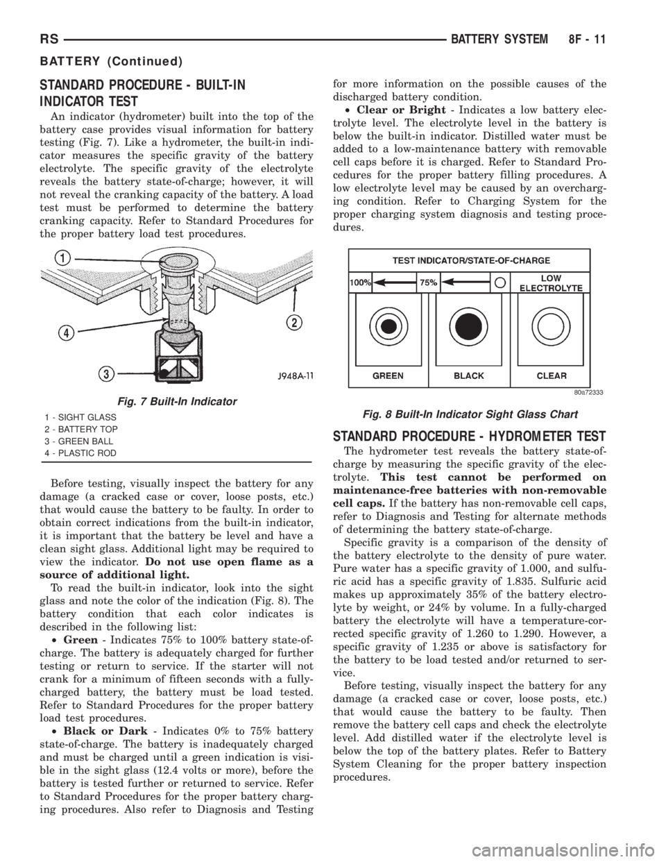
STANDARD PROCEDURE - BUILT-IN
INDICATOR TEST
An indicator (hydrometer) built into the top of the
battery case provides visual information for battery
testing (Fig. 7). Like a hydrometer, the built-in indi-
cator measures the specific gravity of the battery
electrolyte. The specific gravity of the electrolyte
reveals the battery state-of-charge; however, it will
not reveal the cranking capacity of the battery. A load
test must be performed to determine the battery
cranking capacity. Refer to Standard Procedures for
the proper battery load test procedures.
Before testing, visually inspect the battery for any
damage (a cracked case or cover, loose posts, etc.)
that would cause the battery to be faulty. In order to
obtain correct indications from the built-in indicator,
it is important that the battery be level and have a
clean sight glass. Additional light may be required to
view the indicator.Do not use open flame as a
source of additional light.
To read the built-in indicator, look into the sight
glass and note the color of the indication (Fig. 8). The
battery condition that each color indicates is
described in the following list:
²Green- Indicates 75% to 100% battery state-of-
charge. The battery is adequately charged for further
testing or return to service. If the starter will not
crank for a minimum of fifteen seconds with a fully-
charged battery, the battery must be load tested.
Refer to Standard Procedures for the proper battery
load test procedures.
²Black or Dark- Indicates 0% to 75% battery
state-of-charge. The battery is inadequately charged
and must be charged until a green indication is visi-
ble in the sight glass (12.4 volts or more), before the
battery is tested further or returned to service. Refer
to Standard Procedures for the proper battery charg-
ing procedures. Also refer to Diagnosis and Testingfor more information on the possible causes of the
discharged battery condition.
²Clear or Bright- Indicates a low battery elec-
trolyte level. The electrolyte level in the battery is
below the built-in indicator. Distilled water must be
added to a low-maintenance battery with removable
cell caps before it is charged. Refer to Standard Pro-
cedures for the proper battery filling procedures. A
low electrolyte level may be caused by an overcharg-
ing condition. Refer to Charging System for the
proper charging system diagnosis and testing proce-
dures.
STANDARD PROCEDURE - HYDROMETER TEST
The hydrometer test reveals the battery state-of-
charge by measuring the specific gravity of the elec-
trolyte.This test cannot be performed on
maintenance-free batteries with non-removable
cell caps.If the battery has non-removable cell caps,
refer to Diagnosis and Testing for alternate methods
of determining the battery state-of-charge.
Specific gravity is a comparison of the density of
the battery electrolyte to the density of pure water.
Pure water has a specific gravity of 1.000, and sulfu-
ric acid has a specific gravity of 1.835. Sulfuric acid
makes up approximately 35% of the battery electro-
lyte by weight, or 24% by volume. In a fully-charged
battery the electrolyte will have a temperature-cor-
rected specific gravity of 1.260 to 1.290. However, a
specific gravity of 1.235 or above is satisfactory for
the battery to be load tested and/or returned to ser-
vice.
Before testing, visually inspect the battery for any
damage (a cracked case or cover, loose posts, etc.)
that would cause the battery to be faulty. Then
remove the battery cell caps and check the electrolyte
level. Add distilled water if the electrolyte level is
below the top of the battery plates. Refer to Battery
System Cleaning for the proper battery inspection
procedures.
Fig. 7 Built-In Indicator
1 - SIGHT GLASS
2 - BATTERY TOP
3 - GREEN BALL
4 - PLASTIC RODFig. 8 Built-In Indicator Sight Glass Chart
RSBATTERY SYSTEM8F-11
BATTERY (Continued)
Page 1889 of 4284
ENGINE SYSTEMS
TABLE OF CONTENTS
page page
BATTERY SYSTEM - RG ONLY................ 1
CHARGING............................... 5STARTING................................ 7
BATTERY SYSTEM - RG ONLY
TABLE OF CONTENTS
page page
BATTERY
DESCRIPTION............................1
STANDARD PROCEDURE...................2
BATTERY..............................2BATTERY CHARGING....................3
BATTERY CABLES
REMOVAL...............................4
INSTALLATION............................4
BATTERY
DESCRIPTION
There are two different batteries available on this
model. Vehicles equipped with a diesel engine utilize
a spiral wound plate designed battery with recombi-
nation technology. This is a maintenance-free battery
that is capable of delivering more power than a con-
ventional battery. This additional power is required
by a diesel engine during cold cranking. Vehicles
equipped with a gasoline engine utilize a conven-
tional battery. Refer to the following information for
detailed differences and descriptions of these two bat-
teries.
SPIRAL PLATE BATTERY - DIESEL ENGINE
Spiral plate technology takes the elements of tradi-
tional batteries - lead and sulfuric acid - to the next
level. By tightly winding layers of spiral grids and
acid-permeated vitreous separators into cells, the
manufacturer has developed a battery with more
power and service life than conventional batteries the
same size. The spiral plate battery is completely, per-
manently sealed. Through gas recombination, hydro-
gen and oxygen within the battery are captured
during normal charging and reunited to form the
water within the electrolyte, eliminating the need to
add distilled water. Therefore, these batteries have
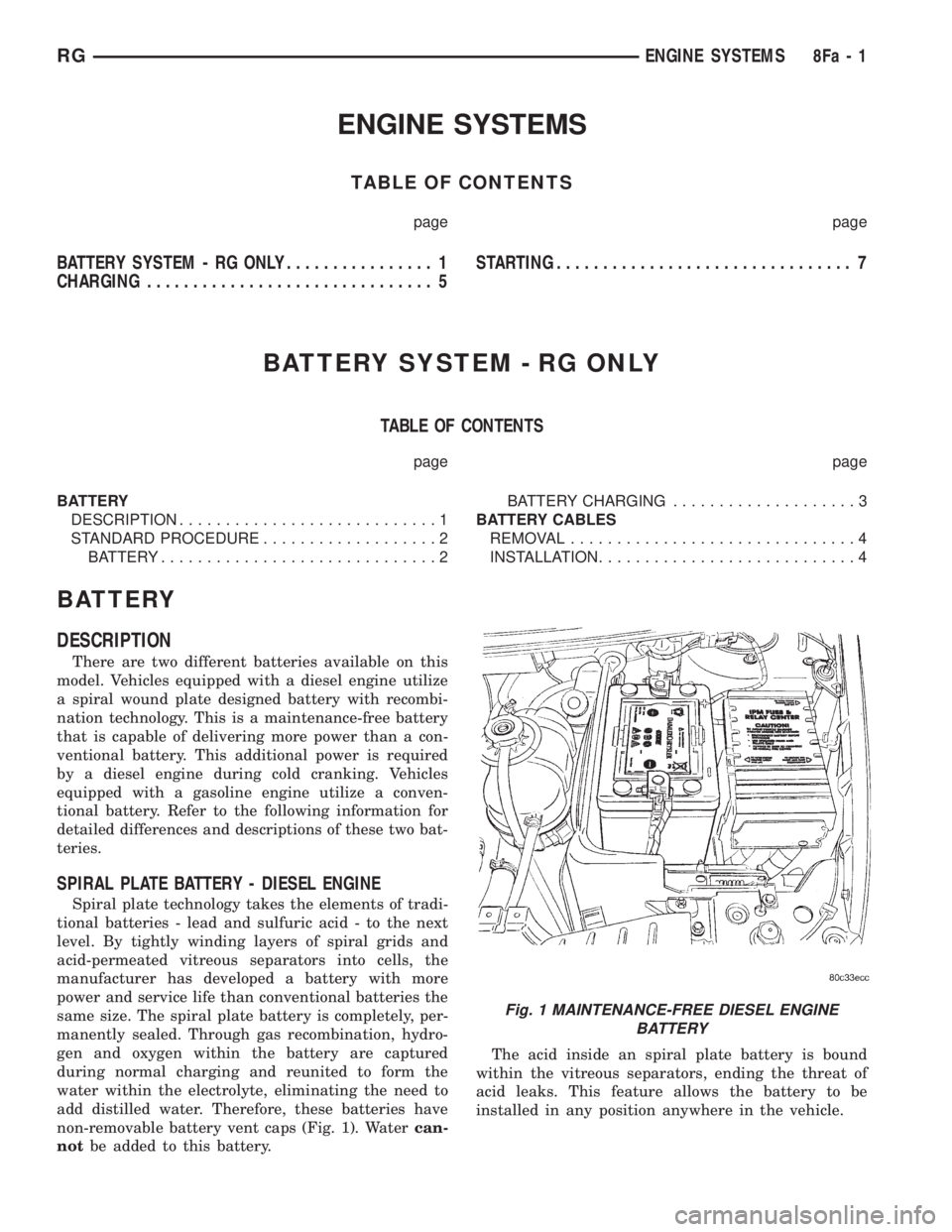
non-removable battery vent caps (Fig. 1). Watercan-
notbe added to this battery.The acid inside an spiral plate battery is bound
within the vitreous separators, ending the threat of
acid leaks. This feature allows the battery to be
installed in any position anywhere in the vehicle.
Fig. 1 MAINTENANCE-FREE DIESEL ENGINE
BATTERY
RGENGINE SYSTEMS8Fa-1
Page 1890 of 4284
Spiral plate technology is the process by which the
plates holding the active material in the battery are
wound tightly in coils instead of hanging flat, like
conventional batteries. This design has a lower inter-
nal resistance and also increases the active material
surface area.
WARNING: NEVER EXCEED 14.4 VOLTS WHEN
CHARGING A SPIRAL PLATE BATTERY. PERSONAL
INJURY AND/OR BATTERY DAMAGE MAY RESULT.
Due to the maintanance-free design, distilled water
cannot be added to this battery. Therefore, if more
than 14.4 volts are used during the spiral plate bat-
tery charging process, water vapor can be exhausted
through the pressure-sensitive battery vents and lost
for good. This can permanently damage the spiral
plate battery. Never exceed 14.4 volts when charging
a spiral plate battery. Personal injury and/or battery
damage may result.
CONVENTIONAL BATTERY - GASOLINE ENGINE
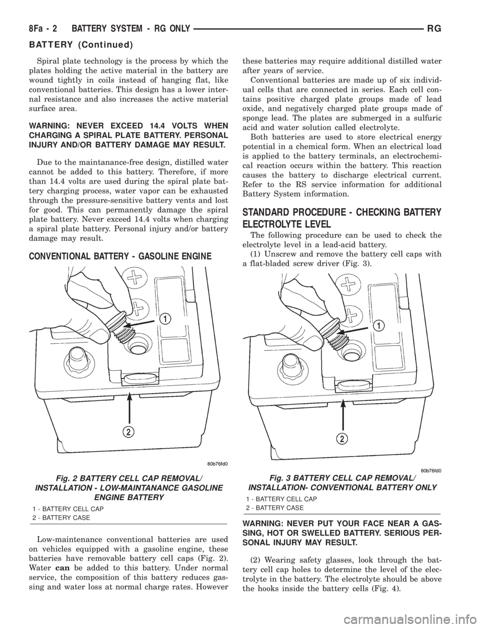
Low-maintenance conventional batteries are used
on vehicles equipped with a gasoline engine, these
batteries have removable battery cell caps (Fig. 2).
Watercanbe added to this battery. Under normal
service, the composition of this battery reduces gas-
sing and water loss at normal charge rates. Howeverthese batteries may require additional distilled water
after years of service.
Conventional batteries are made up of six individ-
ual cells that are connected in series. Each cell con-
tains positive charged plate groups made of lead
oxide, and negatively charged plate groups made of
sponge lead. The plates are submerged in a sulfuric
acid and water solution called electrolyte.
Both batteries are used to store electrical energy
potential in a chemical form. When an electrical load
is applied to the battery terminals, an electrochemi-
cal reaction occurs within the battery. This reaction
causes the battery to discharge electrical current.
Refer to the RS service information for additional
Battery System information.
STANDARD PROCEDURE - CHECKING BATTERY
ELECTROLYTE LEVEL
The following procedure can be used to check the
electrolyte level in a lead-acid battery.
(1) Unscrew and remove the battery cell caps with
a flat-bladed screw driver (Fig. 3).
WARNING: NEVER PUT YOUR FACE NEAR A GAS-
SING, HOT OR SWELLED BATTERY. SERIOUS PER-
SONAL INJURY MAY RESULT.
(2) Wearing safety glasses, look through the bat-
tery cell cap holes to determine the level of the elec-
trolyte in the battery. The electrolyte should be above
the hooks inside the battery cells (Fig. 4).
Fig. 2 BATTERY CELL CAP REMOVAL/
INSTALLATION - LOW-MAINTANANCE GASOLINE
ENGINE BATTERY
1 - BATTERY CELL CAP
2 - BATTERY CASE
Fig. 3 BATTERY CELL CAP REMOVAL/
INSTALLATION- CONVENTIONAL BATTERY ONLY
1 - BATTERY CELL CAP
2 - BATTERY CASE
8Fa - 2 BATTERY SYSTEM - RG ONLYRG
BATTERY (Continued)
Page 1924 of 4284
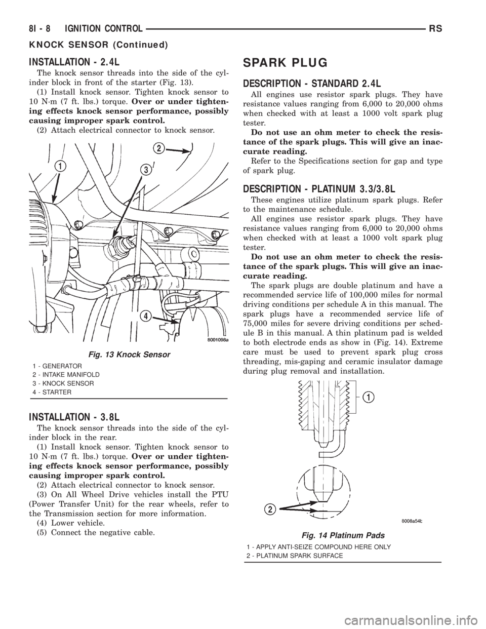
INSTALLATION - 2.4L
The knock sensor threads into the side of the cyl-
inder block in front of the starter (Fig. 13).
(1) Install knock sensor. Tighten knock sensor to
10 N´m (7 ft. lbs.) torque.Over or under tighten-
ing effects knock sensor performance, possibly
causing improper spark control.
(2) Attach electrical connector to knock sensor.
INSTALLATION - 3.8L
The knock sensor threads into the side of the cyl-
inder block in the rear.
(1) Install knock sensor. Tighten knock sensor to
10 N´m (7 ft. lbs.) torque.Over or under tighten-
ing effects knock sensor performance, possibly
causing improper spark control.
(2) Attach electrical connector to knock sensor.
(3) On All Wheel Drive vehicles install the PTU
(Power Transfer Unit) for the rear wheels, refer to
the Transmission section for more information.
(4) Lower vehicle.
(5) Connect the negative cable.
SPARK PLUG
DESCRIPTION - STANDARD 2.4L
All engines use resistor spark plugs. They have
resistance values ranging from 6,000 to 20,000 ohms
when checked with at least a 1000 volt spark plug
tester.
Do not use an ohm meter to check the resis-
tance of the spark plugs. This will give an inac-
curate reading.
Refer to the Specifications section for gap and type
of spark plug.
DESCRIPTION - PLATINUM 3.3/3.8L
These engines utilize platinum spark plugs. Refer
to the maintenance schedule.
All engines use resistor spark plugs. They have
resistance values ranging from 6,000 to 20,000 ohms
when checked with at least a 1000 volt spark plug
tester.
Do not use an ohm meter to check the resis-
tance of the spark plugs. This will give an inac-
curate reading.
The spark plugs are double platinum and have a
recommended service life of 100,000 miles for normal
driving conditions per schedule A in this manual. The
spark plugs have a recommended service life of
75,000 miles for severe driving conditions per sched-
ule B in this manual. A thin platinum pad is welded
to both electrode ends as show in (Fig. 14). Extreme
care must be used to prevent spark plug cross
threading, mis-gaping and ceramic insulator damage
during plug removal and installation.
Fig. 13 Knock Sensor
1 - GENERATOR
2 - INTAKE MANIFOLD
3 - KNOCK SENSOR
4-STARTER
Fig. 14 Platinum Pads
1 - APPLY ANTI-SEIZE COMPOUND HERE ONLY
2 - PLATINUM SPARK SURFACE
8I - 8 IGNITION CONTROLRS
KNOCK SENSOR (Continued)