2001 CHRYSLER VOYAGER display
[x] Cancel search: displayPage 252 of 4284

TEST ACTION APPLICABILITY
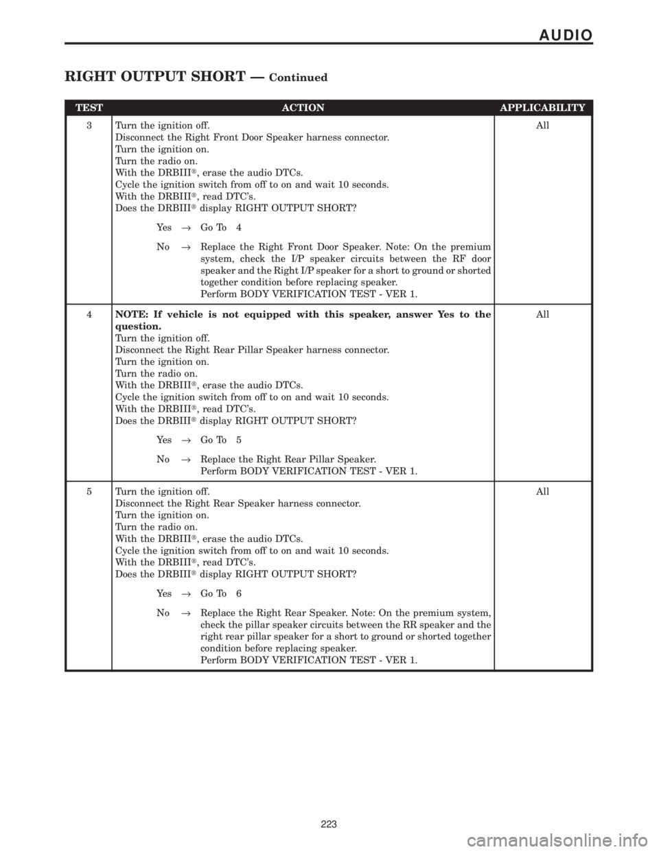
3 Turn the ignition off.
Disconnect the Right Front Door Speaker harness connector.
Turn the ignition on.
Turn the radio on.
With the DRBIIIt, erase the audio DTCs.
Cycle the ignition switch from off to on and wait 10 seconds.
With the DRBIIIt, read DTC's.
Does the DRBIIItdisplay RIGHT OUTPUT SHORT?All
Ye s®Go To 4
No®Replace the Right Front Door Speaker. Note: On the premium
system, check the I/P speaker circuits between the RF door
speaker and the Right I/P speaker for a short to ground or shorted
together condition before replacing speaker.
Perform BODY VERIFICATION TEST - VER 1.
4NOTE: If vehicle is not equipped with this speaker, answer Yes to the
question.
Turn the ignition off.
Disconnect the Right Rear Pillar Speaker harness connector.
Turn the ignition on.
Turn the radio on.
With the DRBIIIt, erase the audio DTCs.
Cycle the ignition switch from off to on and wait 10 seconds.
With the DRBIIIt, read DTC's.
Does the DRBIIItdisplay RIGHT OUTPUT SHORT?All
Ye s®Go To 5
No®Replace the Right Rear Pillar Speaker.
Perform BODY VERIFICATION TEST - VER 1.
5 Turn the ignition off.
Disconnect the Right Rear Speaker harness connector.
Turn the ignition on.
Turn the radio on.
With the DRBIIIt, erase the audio DTCs.
Cycle the ignition switch from off to on and wait 10 seconds.
With the DRBIIIt, read DTC's.
Does the DRBIIItdisplay RIGHT OUTPUT SHORT?All
Ye s®Go To 6
No®Replace the Right Rear Speaker. Note: On the premium system,
check the pillar speaker circuits between the RR speaker and the
right rear pillar speaker for a short to ground or shorted together
condition before replacing speaker.
Perform BODY VERIFICATION TEST - VER 1.
223
AUDIO
RIGHT OUTPUT SHORT ÐContinued
Page 254 of 4284

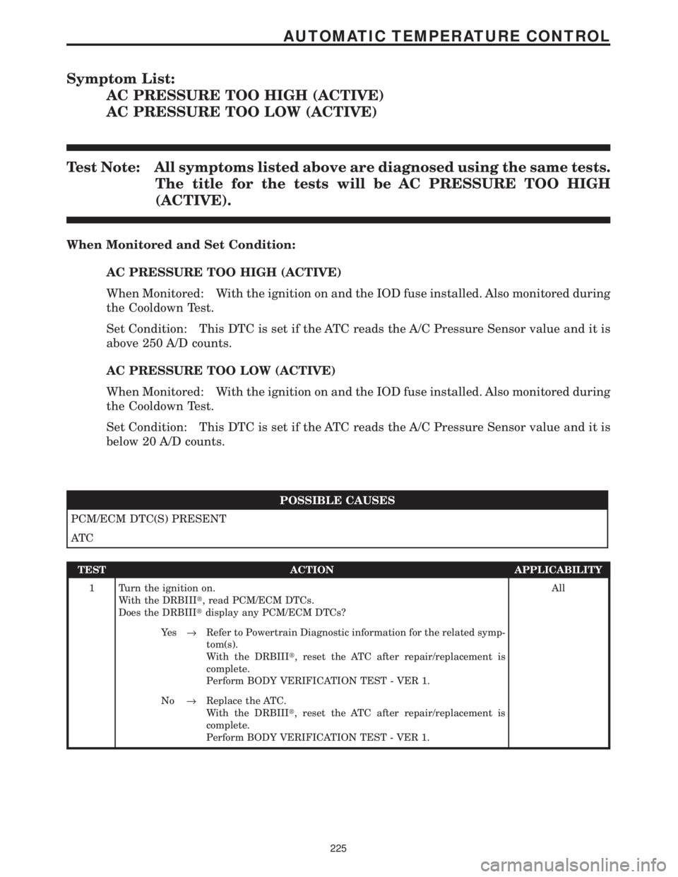
Symptom List:
AC PRESSURE TOO HIGH (ACTIVE)
AC PRESSURE TOO LOW (ACTIVE)
Test Note: All symptoms listed above are diagnosed using the same tests.
The title for the tests will be AC PRESSURE TOO HIGH
(ACTIVE).
When Monitored and Set Condition:
AC PRESSURE TOO HIGH (ACTIVE)
When Monitored: With the ignition on and the IOD fuse installed. Also monitored during
the Cooldown Test.
Set Condition: This DTC is set if the ATC reads the A/C Pressure Sensor value and it is
above 250 A/D counts.
AC PRESSURE TOO LOW (ACTIVE)
When Monitored: With the ignition on and the IOD fuse installed. Also monitored during
the Cooldown Test.
Set Condition: This DTC is set if the ATC reads the A/C Pressure Sensor value and it is
below 20 A/D counts.
POSSIBLE CAUSES
PCM/ECM DTC(S) PRESENT
AT C
TEST ACTION APPLICABILITY
1 Turn the ignition on.
With the DRBIIIt, read PCM/ECM DTCs.
Does the DRBIIItdisplay any PCM/ECM DTCs?All
Ye s®Refer to Powertrain Diagnostic information for the related symp-
tom(s).
With the DRBIIIt, reset the ATC after repair/replacement is
complete.
Perform BODY VERIFICATION TEST - VER 1.
No®Replace the ATC.
With the DRBIIIt, reset the ATC after repair/replacement is
complete.
Perform BODY VERIFICATION TEST - VER 1.
225
AUTOMATIC TEMPERATURE CONTROL
Page 260 of 4284

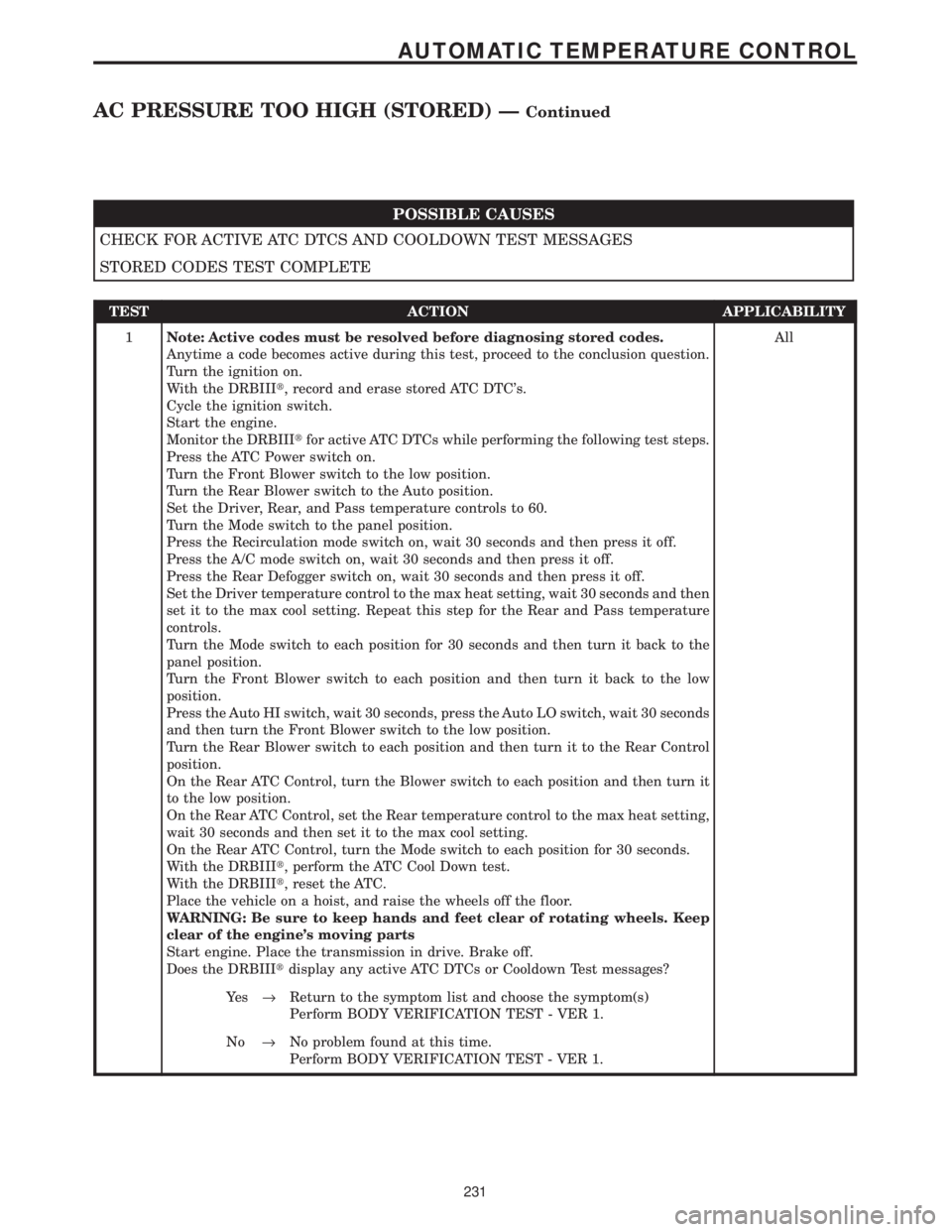
POSSIBLE CAUSES
CHECK FOR ACTIVE ATC DTCS AND COOLDOWN TEST MESSAGES
STORED CODES TEST COMPLETE
TEST ACTION APPLICABILITY
1Note: Active codes must be resolved before diagnosing stored codes.
Anytime a code becomes active during this test, proceed to the conclusion question.
Turn the ignition on.
With the DRBIIIt, record and erase stored ATC DTC's.
Cycle the ignition switch.
Start the engine.
Monitor the DRBIIItfor active ATC DTCs while performing the following test steps.
Press the ATC Power switch on.
Turn the Front Blower switch to the low position.
Turn the Rear Blower switch to the Auto position.
Set the Driver, Rear, and Pass temperature controls to 60.
Turn the Mode switch to the panel position.
Press the Recirculation mode switch on, wait 30 seconds and then press it off.
Press the A/C mode switch on, wait 30 seconds and then press it off.
Press the Rear Defogger switch on, wait 30 seconds and then press it off.
Set the Driver temperature control to the max heat setting, wait 30 seconds and then
set it to the max cool setting. Repeat this step for the Rear and Pass temperature
controls.
Turn the Mode switch to each position for 30 seconds and then turn it back to the
panel position.
Turn the Front Blower switch to each position and then turn it back to the low
position.
Press the Auto HI switch, wait 30 seconds, press the Auto LO switch, wait 30 seconds
and then turn the Front Blower switch to the low position.
Turn the Rear Blower switch to each position and then turn it to the Rear Control
position.
On the Rear ATC Control, turn the Blower switch to each position and then turn it
to the low position.
On the Rear ATC Control, set the Rear temperature control to the max heat setting,
wait 30 seconds and then set it to the max cool setting.
On the Rear ATC Control, turn the Mode switch to each position for 30 seconds.
With the DRBIIIt, perform the ATC Cool Down test.
With the DRBIIIt, reset the ATC.
Place the vehicle on a hoist, and raise the wheels off the floor.
WARNING: Be sure to keep hands and feet clear of rotating wheels. Keep
clear of the engine's moving parts
Start engine. Place the transmission in drive. Brake off.
Does the DRBIIItdisplay any active ATC DTCs or Cooldown Test messages?All
Ye s®Return to the symptom list and choose the symptom(s)
Perform BODY VERIFICATION TEST - VER 1.
No®No problem found at this time.
Perform BODY VERIFICATION TEST - VER 1.
231
AUTOMATIC TEMPERATURE CONTROL
AC PRESSURE TOO HIGH (STORED) ÐContinued
Page 261 of 4284

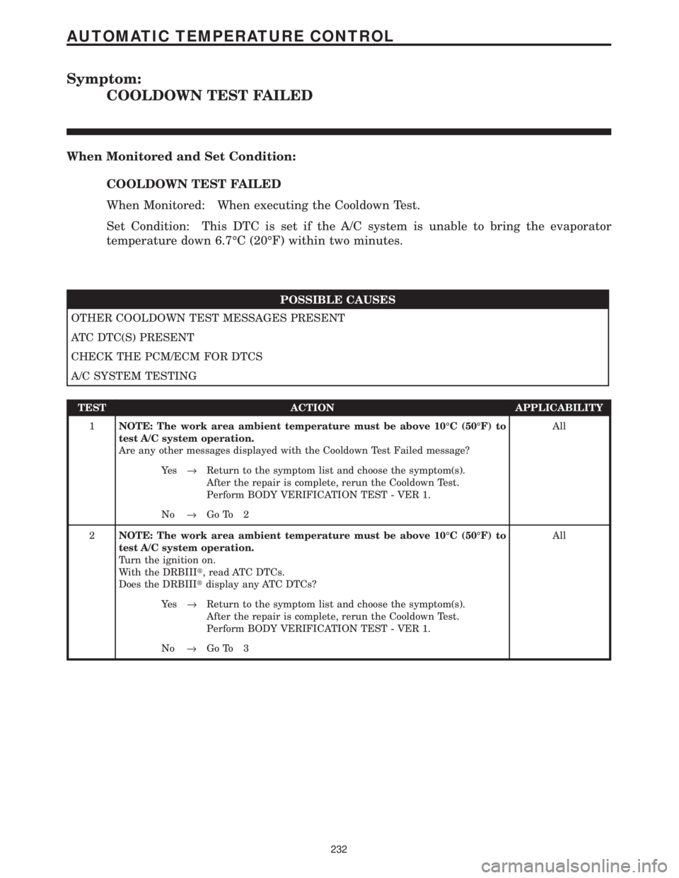
Symptom:
COOLDOWN TEST FAILED
When Monitored and Set Condition:
COOLDOWN TEST FAILED
When Monitored: When executing the Cooldown Test.
Set Condition: This DTC is set if the A/C system is unable to bring the evaporator
temperature down 6.7ÉC (20ÉF) within two minutes.
POSSIBLE CAUSES
OTHER COOLDOWN TEST MESSAGES PRESENT
ATC DTC(S) PRESENT
CHECK THE PCM/ECM FOR DTCS
A/C SYSTEM TESTING
TEST ACTION APPLICABILITY
1NOTE: The work area ambient temperature must be above 10ÉC (50ÉF) to
test A/C system operation.
Are any other messages displayed with the Cooldown Test Failed message?All
Ye s®Return to the symptom list and choose the symptom(s).
After the repair is complete, rerun the Cooldown Test.
Perform BODY VERIFICATION TEST - VER 1.
No®Go To 2
2NOTE: The work area ambient temperature must be above 10ÉC (50ÉF) to
test A/C system operation.
Turn the ignition on.
With the DRBIIIt, read ATC DTCs.
Does the DRBIIItdisplay any ATC DTCs?All
Ye s®Return to the symptom list and choose the symptom(s).
After the repair is complete, rerun the Cooldown Test.
Perform BODY VERIFICATION TEST - VER 1.
No®Go To 3
232
AUTOMATIC TEMPERATURE CONTROL
Page 270 of 4284

Symptom:
EVAP TEMP SENSOR OPEN
When Monitored and Set Condition:
EVAP TEMP SENSOR OPEN
When Monitored: During the Cooldown Test.
Set Condition: This message is displayed if the ATC detects an abnormally high voltage
on the evaporator temperature sensor signal during the Cooldown Test.
POSSIBLE CAUSES
EVAPORATOR TEMPERATURE SENSOR
EVAPORATOR TEMPERATURE SENSOR SIGNAL CIRCUIT OPEN
SENSOR GROUND CIRCUIT OPEN
AT C
TEST ACTION APPLICABILITY
1 Turn the ignition off.
Disconnect the in-line C202 harness connector.
Connect a jumper wire between the Evaporator Temperature Sensor Signal circuit
and the Sensor Ground circuit at the in-line C202 harness connector (HVAC side).
Turn the ignition on.
With the DRBIIItin Sensor Display, read the Evaporator Temperature Sensor
voltage.
Does the DRBIIItdisplay: 0.0 volts?All
Ye s®Check the wiring harness between the in-line C202 harness
connector (plenum side) and the Evap Temp Sensor for an open.
Repair as necessary. If Ok, replace the Evaporator Temperature
Sensor.
With the DRBIIIt, reset the ATC after repair/replacement is
complete.
Perform BODY VERIFICATION TEST - VER 1.
No®Go To 2
2 Turn the ignition off.
Disconnect the ATC C2 harness connector.
Disconnect the in-line C202 harness connector.
Measure the resistance of the Evaporator Temperature Sensor Signal circuit between
the ATC C2 harness connector and the in-line C202 harness connector.
Is the resistance below 5.0 ohms?All
Ye s®Go To 3
No®Repair the Evaporator Temperature Sensor Signal circuit be-
tween the ATC C2 harness connector and the in-line C202
harness connector (HVAC side) for an open.
With the DRBIIIt, reset the ATC after repair/replacement is
complete.
Perform BODY VERIFICATION TEST - VER 1.
241
AUTOMATIC TEMPERATURE CONTROL
Page 272 of 4284

Symptom:
EVAP TEMP SENSOR SHORTED
When Monitored and Set Condition:
EVAP TEMP SENSOR SHORTED
When Monitored: During the Cooldown Test.
Set Condition: This message is displayed if the ATC detects an abnormally low voltage on
the evaporator temperature sensor signal during the Cooldown Test.
POSSIBLE CAUSES
EVAPORATOR TEMPERATURE SENSOR
EVAPORATOR TEMPERATURE SENSOR SIGNAL CIRCUIT SHORT TO GROUND
EVAPORATOR TEMPERATURE SENSOR SIGNAL CIRCUIT SHORT TO SENSOR GROUND CIR-
CUIT
AT C
TEST ACTION APPLICABILITY
1 Turn the ignition off.
Disconnect the in-line C202 harness connector.
Turn the ignition on.
With the DRBIIItin Sensor Display, read the Evaporator Temperature Sensor
voltage.
Does the DRBIIItdisplay: 5.0 volts or greater?All
Ye s®Check the Evap Temp Sensor Signal circuit between the in-line
C202 harness connector (plenum side) and the Evap Temp Sensor
for a short to ground. Repair as necessary. If Ok, replace the
Evaporator Temperature Sensor.
With the DRBIIIt, reset the ATC after repair/replacement is
complete.
Perform BODY VERIFICATION TEST - VER 1.
No®Go To 2
2 Turn the ignition off.
Disconnect the ATC C2 harness connector.
Disconnect the in-line C202 harness connector.
Measure the resistance between ground and the Evaporator Temperature Sensor
Signal circuit (HVAC side).
Is the resistance above 100k ohms?All
Ye s®Go To 3
No®Repair the Evaporator Temperature Sensor Signal circuit be-
tween the ATC C2 harness connector and the in-line C202
harness connector (HVAC side) for a short to ground.
With the DRBIIIt, reset the ATC after repair/replacement is
complete.
Perform BODY VERIFICATION TEST - VER 1.
243
AUTOMATIC TEMPERATURE CONTROL
Page 276 of 4284

TEST ACTION APPLICABILITY
2 Turn the ignition off.
Disconnect the ATC Remote Sensor harness connector.
Turn the ignition on.
Measure the voltage of the KDB 2 Data circuit.
Is the voltage above 10.0 volts?All
Ye s®Go To 3
No®Go To 13
3 Turn the ignition off.
Disconnect the ATC Remote Sensor harness connector.
Disconnect the ATC C3 harness connector.
Turn the ignition on.
Measure the voltage of the KDB 2 Data circuit.
Is the voltage above 1.0 volt?All
Ye s®Repair the KDB 2 Data circuit for a short to voltage.
With the DRBIIIt, reset the ATC after repair/replacement is
complete.
Perform BODY VERIFICATION TEST - VER 1.
No®Go To 4
4 Turn the ignition off.
Disconnect the ATC Remote Sensor harness connector.
Use Scope input cable CH7058, Cable to Probe adapter CH7062, and the red and
black test probes.
Connect the scope input cable to the channel one connector on the DRB. Attach the
red and black leads and the cable to probe adapter to the scope input cable.
Select Lab Scope.
Select Live.
Select 12 volt square wave.
Press F2 for Scope.
Press F2 and use the arrows to set the voltage range to 20 volts, the Offset to 4.0, and
the Probe to x10. Press F2 again and set the divisions to 40ms/Div, then press F2
again when complete.
Connect the Black lead to the chassis ground. Connect the Red lead to the KDB 2
Clock circuit in the ATC Remote Sensor harness connector.
Turn the ignition on.
Observe the voltage display on the DRB Lab Scope.
NOTE: The lab scope pattern should look similar to the example given in the
support material and cycle from approximately 0 volts to 8.0 volts.
Did the lab scope pattern and voltage react as noted above?All
Ye s®Go To 5
No®Go To 9
5 Turn the ignition off.
Disconnect the ATC Remote Sensor harness connector.
Measure the resistance between ground and the Sensor Return circuit.
Is the resistance below 10 ohms?All
Ye s®Go To 6
No®Go To 7
247
AUTOMATIC TEMPERATURE CONTROL
FRONT IR SENSOR NOT CALIBRATED (ACTIVE) ÐContinued
Page 287 of 4284

Symptom:
INVALID CONDITIONS FOR COOLDOWN TEST, EVAP TEMPERA-
TURE TOO LOW
When Monitored and Set Condition:
INVALID CONDITIONS FOR COOLDOWN TEST, EVAP TEMPERATURE TOO
LOW
When Monitored: When executing the Cooldown Test.
Set Condition: This message will be displayed if the A/C - Heater Control Module sees
evaporator temperature below 12.7ÉC (55ÉF) when executing the Cooldown Test.
POSSIBLE CAUSES
EVAPORATOR TEMPERATURE TOO LOW
ATC DTC(S) PRESENT
CHECK THE PCM/ECM FOR DTCS
EVAPORATOR TEMPERATURE SENSOR
SENSOR GROUND CIRCUIT HIGH RESISTANCE
EVAPORATOR TEMPERATURE SENSOR SIGNAL CIRCUIT HIGH RESISTANCE
AUTOMATIC TEMPERATURE CONTROL
TEST ACTION APPLICABILITY
1CAUTION: The work area ambient temperature must be above 15.6ÉC (60ÉF)
to test A/C system operation.
Start the engine.
Turn the A/C off.
Turn the Blower on high. Allow the blower to run for 5 minutes to ensure that the
Evaporator Temperature Sensor temperature is above 12.7ÉC (55ÉF).
With the DRBIIIt, actuate the Cooldown Test.
Does the DRBIIItdisplay: Cooldown Test Too Cold To Start?All
Ye s®Go To 2
No®Perform additional testing as necessary.
Perform BODY VERIFICATION TEST - VER 1.
2CAUTION: The work area ambient temperature must be above 15.6ÉC (60ÉF)
to test A/C system operation.
Turn the ignition on.
With the DRBIIIt, read ATC DTCs.
Does the DRBIIItdisplay any ATC DTCs?All
Ye s®Return to the symptom list and choose the symptom(s). After the
repair is complete, with the DRBIIIt, erase the DTC(s). Cycle the
ignition switch. With the DRBIIIt, reset the ATC. With the
DRBIIIt, actuate the Cooldown Test.
Perform BODY VERIFICATION TEST - VER 1.
No®Go To 3
258
AUTOMATIC TEMPERATURE CONTROL