2001 CHRYSLER VOYAGER air condition
[x] Cancel search: air conditionPage 2706 of 4284
REMOVAL - ENGINE ASSEMBLY
(1) Perform fuel pressure release procedure. (Refer
to 14 - FUEL SYSTEM/FUEL DELIVERY - STAN-
DARD PROCEDURE)
(2) Disconnect the battery.
(3) Remove air cleaner and hoses.
(4) Disconnect the fuel line from fuel rail. (Refer to
14 - FUEL SYSTEM/FUEL DELIVERY/QUICK
CONNECT FITTING - STANDARD PROCEDURE)
(5) Remove the wiper module. (Refer to 8 - ELEC-
TRICAL/WIPERS/WASHERS/WIPER MODULE -
REMOVAL)
(6) Block off heater hoses to the rear heater sys-
tem, if equipped, using pinch-off pliers.
(7) Drain the cooling system. (Refer to 7 - COOL-
ING - STANDARD PROCEDURE)
(8) Disconnect the heater hoses.
(9) Remove the radiator upper support crossmem-
ber. (Refer to 23 - BODY/EXTERIOR/GRILLE OPEN-
ING REINFORCEMENT - REMOVAL)
(10) Remove the radiator fans. (Refer to 7 - COOL-
ING/ENGINE/RADIATOR FAN - REMOVAL)
(11) Disconnect the throttle cables from the throt-
tle body.
(12) Disconnect the MAP, IAC, and TPS electrical
connectors.
(13) Disconnect the EGR transducer electrical con-
nector.
(14) Disconnect the vacuum hoses from throttle
body.
(15) Disconnect the brake booster and speed con-
trol vacuum hoses.(16) Disengage wire harness clip from the right
side engine mount.
(17) Remove the power steering reservoir from
mounting position and set aside. Do not disconnect
hose.
(18) Disconnect ground strap from rear of cylinder
head.
(19) Disconnect engine coolant temperature (ECT)
sensor and ignition coil electrical connectors.
(20) Disconnect the fuel injector electrical harness
connector and disengage clip from support bracket.
(21) Disconnect crank sensor connector.
(22) Disconnect camshaft sensor connector.
(23) Evacuate air conditioning system.
(24) Disconnect A/C compressor electrical connec-
tor.
(25) Disconnect the A/C lines from compressor.
Cover and seal all openings of hoses and compressor.
(26) Remove the radiator upper hose.
(27) Disengage electrical harness clip at transaxle
dipstick tube.
(28) Remove transaxle dipstick tube. Seal opening
using a suitable plug.
(29) Disconnect cooler hoses from transaxle.
(30) Disconnect transaxle shift linkage and electri-
cal connectors.
(31) Raise vehicle on hoist and drain the engine
oil.
(32) Remove the axle shafts. (Refer to 3 - DIFFER-
ENTIAL & DRIVELINE/HALF SHAFT - REMOVAL)
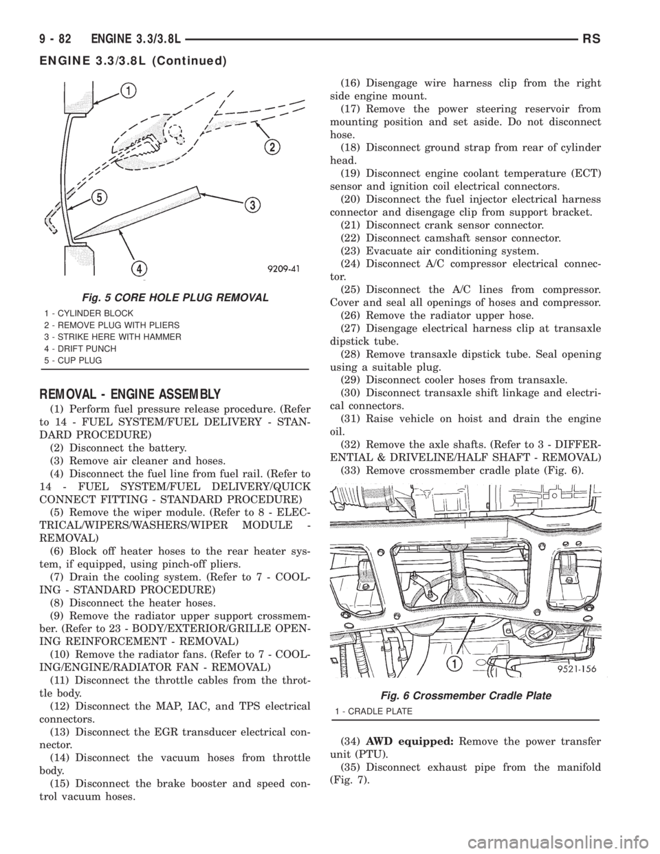
(33) Remove crossmember cradle plate (Fig. 6).
(34)AWD equipped:Remove the power transfer
unit (PTU).
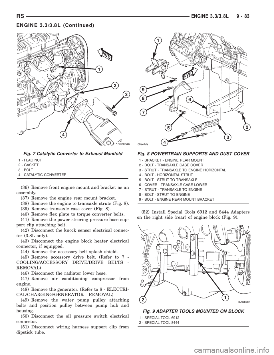
(35) Disconnect exhaust pipe from the manifold
(Fig. 7).
Fig. 5 CORE HOLE PLUG REMOVAL
1 - CYLINDER BLOCK
2 - REMOVE PLUG WITH PLIERS
3 - STRIKE HERE WITH HAMMER
4 - DRIFT PUNCH
5 - CUP PLUG
Fig. 6 Crossmember Cradle Plate
1 - CRADLE PLATE
9 - 82 ENGINE 3.3/3.8LRS
ENGINE 3.3/3.8L (Continued)
Page 2707 of 4284
(36) Remove front engine mount and bracket as an
assembly.
(37) Remove the engine rear mount bracket.
(38) Remove the engine to transaxle struts (Fig. 8).
(39) Remove transaxle case cover (Fig. 8).
(40) Remove flex plate to torque converter bolts.
(41) Remove the power steering pressure hose sup-
port clip attaching bolt.
(42) Disconnect the knock sensor electrical connec-
tor (3.8L only).
(43) Disconnect the engine block heater electrical
connector, if equipped.
(44) Remove the accessory belt splash shield.
(45) Remove accessory drive belt. (Refer to 7 -
COOLING/ACCESSORY DRIVE/DRIVE BELTS -
REMOVAL)
(46) Disconnect the radiator lower hose.
(47) Remove air conditioning compressor from
engine.
(48) Remove the generator. (Refer to 8 - ELECTRI-
CAL/CHARGING/GENERATOR - REMOVAL)
(49) Remove the water pump pulley attaching
bolts and position pulley between pump hub and
housing.
(50) Disconnect the oil pressure switch electrical
connector.
(51) Disconnect wiring harness support clip from
dipstick tube.(52) Install Special Tools 6912 and 8444 Adapters
on the right side (rear) of engine block (Fig. 9).
Fig. 7 Catalytic Converter to Exhaust Manifold
1 - FLAG NUT
2 - GASKET
3 - BOLT
4 - CATALYTIC CONVERTER
Fig. 8 POWERTRAIN SUPPORTS AND DUST COVER
1 - BRACKET - ENGINE REAR MOUNT
2 - BOLT - TRANSAXLE CASE COVER
3 - STRUT - TRANSAXLE TO ENGINE HORIZONTAL
4 - BOLT - HORIZONTAL STRUT
5 - BOLT - STRUT TO TRANSAXLE
6 - COVER - TRANSAXLE CASE LOWER
7 - STRUT - TRANSAXLE TO ENGINE
8 - BOLT - STRUT TO ENGINE
9 - BOLT - ENGINE REAR MOUNT BRACKET
Fig. 9 ADAPTER TOOLS MOUNTED ON BLOCK
1 - SPECIAL TOOL 6912
2 - SPECIAL TOOL 8444
RSENGINE 3.3/3.8L9-83
ENGINE 3.3/3.8L (Continued)
Page 2727 of 4284
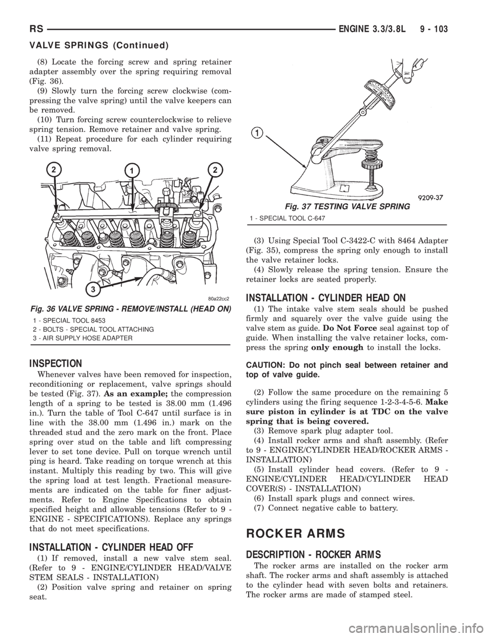
(8) Locate the forcing screw and spring retainer
adapter assembly over the spring requiring removal
(Fig. 36).
(9) Slowly turn the forcing screw clockwise (com-
pressing the valve spring) until the valve keepers can
be removed.
(10) Turn forcing screw counterclockwise to relieve
spring tension. Remove retainer and valve spring.
(11) Repeat procedure for each cylinder requiring
valve spring removal.
INSPECTION
Whenever valves have been removed for inspection,
reconditioning or replacement, valve springs should
be tested (Fig. 37).As an example;the compression
length of a spring to be tested is 38.00 mm (1.496
in.). Turn the table of Tool C-647 until surface is in
line with the 38.00 mm (1.496 in.) mark on the
threaded stud and the zero mark on the front. Place
spring over stud on the table and lift compressing
lever to set tone device. Pull on torque wrench until
ping is heard. Take reading on torque wrench at this
instant. Multiply this reading by two. This will give
the spring load at test length. Fractional measure-
ments are indicated on the table for finer adjust-
ments. Refer to Engine Specifications to obtain
specified height and allowable tensions (Refer to 9 -
ENGINE - SPECIFICATIONS). Replace any springs
that do not meet specifications.
INSTALLATION - CYLINDER HEAD OFF
(1) If removed, install a new valve stem seal.
(Refer to 9 - ENGINE/CYLINDER HEAD/VALVE
STEM SEALS - INSTALLATION)
(2) Position valve spring and retainer on spring
seat.(3) Using Special Tool C-3422-C with 8464 Adapter
(Fig. 35), compress the spring only enough to install
the valve retainer locks.
(4) Slowly release the spring tension. Ensure the
retainer locks are seated properly.
INSTALLATION - CYLINDER HEAD ON
(1)The intake valve stem seals should be pushed
firmly and squarely over the valve guide using the
valve stem as guide.Do Not Force
seal against top of
guide. When installing the valve retainer locks, com-
press the springonly enoughto install the locks.
CAUTION: Do not pinch seal between retainer and
top of valve guide.
(2) Follow the same procedure on the remaining 5
cylinders using the firing sequence 1-2-3-4-5-6.Make
sure piston in cylinder is at TDC on the valve
spring that is being covered.
(3) Remove spark plug adapter tool.
(4) Install rocker arms and shaft assembly. (Refer
to 9 - ENGINE/CYLINDER HEAD/ROCKER ARMS -
INSTALLATION)
(5) Install cylinder head covers. (Refer to 9 -
ENGINE/CYLINDER HEAD/CYLINDER HEAD
COVER(S) - INSTALLATION)
(6) Install spark plugs and connect wires.
(7) Connect negative cable to battery.
ROCKER ARMS
DESCRIPTION - ROCKER ARMS
The rocker arms are installed on the rocker arm
shaft. The rocker arms and shaft assembly is attached
to the cylinder head with seven bolts and retainers.
The rocker arms are made of stamped steel.
Fig. 36 VALVE SPRING - REMOVE/INSTALL (HEAD ON)
1 - SPECIAL TOOL 8453
2 - BOLTS - SPECIAL TOOL ATTACHING
3 - AIR SUPPLY HOSE ADAPTER
Fig. 37 TESTING VALVE SPRING
1 - SPECIAL TOOL C-647
RSENGINE 3.3/3.8L9 - 103
VALVE SPRINGS (Continued)
Page 2742 of 4284
FLEX PLATE
REMOVAL
(1) Remove the transaxle. (Refer to 21 - TRANS-
MISSION/TRANSAXLE/AUTOMATIC - 31TH -
REMOVAL) (Refer to 21 - TRANSMISSION/TRAN-
SAXLE/AUTOMATIC - 41TE - REMOVAL)
(2) Remove flex plate attaching bolts.
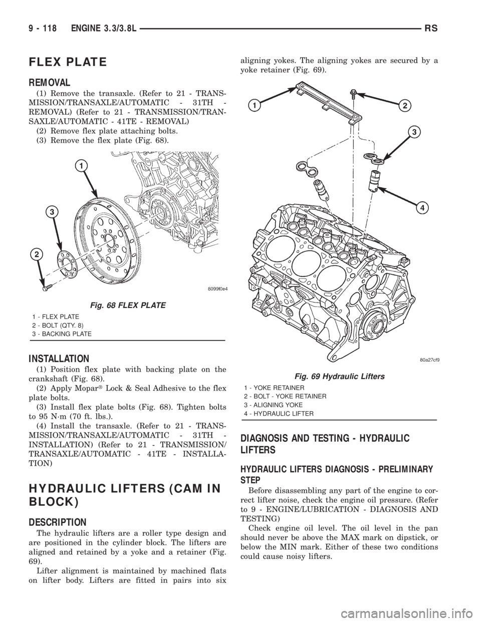
(3) Remove the flex plate (Fig. 68).
INSTALLATION
(1) Position flex plate with backing plate on the
crankshaft (Fig. 68).
(2) Apply MopartLock & Seal Adhesive to the flex
plate bolts.
(3) Install flex plate bolts (Fig. 68). Tighten bolts
to 95 N´m (70 ft. lbs.).
(4) Install the transaxle. (Refer to 21 - TRANS-
MISSION/TRANSAXLE/AUTOMATIC - 31TH -
INSTALLATION) (Refer to 21 - TRANSMISSION/
TRANSAXLE/AUTOMATIC - 41TE - INSTALLA-
TION)
HYDRAULIC LIFTERS (CAM IN
BLOCK)
DESCRIPTION
The hydraulic lifters are a roller type design and
are positioned in the cylinder block. The lifters are
aligned and retained by a yoke and a retainer (Fig.
69).
Lifter alignment is maintained by machined flats
on lifter body. Lifters are fitted in pairs into sixaligning yokes. The aligning yokes are secured by a
yoke retainer (Fig. 69).
DIAGNOSIS AND TESTING - HYDRAULIC
LIFTERS
HYDRAULIC LIFTERS DIAGNOSIS - PRELIMINARY
STEP
Before disassembling any part of the engine to cor-
rect lifter noise, check the engine oil pressure. (Refer
to 9 - ENGINE/LUBRICATION - DIAGNOSIS AND
TESTING)
Check engine oil level. The oil level in the pan
should never be above the MAX mark on dipstick, or
below the MIN mark. Either of these two conditions
could cause noisy lifters.
Fig. 68 FLEX PLATE
1 - FLEX PLATE
2 - BOLT (QTY. 8)
3 - BACKING PLATE
Fig. 69 Hydraulic Lifters
1 - YOKE RETAINER
2 - BOLT - YOKE RETAINER
3 - ALIGNING YOKE
4 - HYDRAULIC LIFTER
9 - 118 ENGINE 3.3/3.8LRS
Page 2760 of 4284
OIL PAN
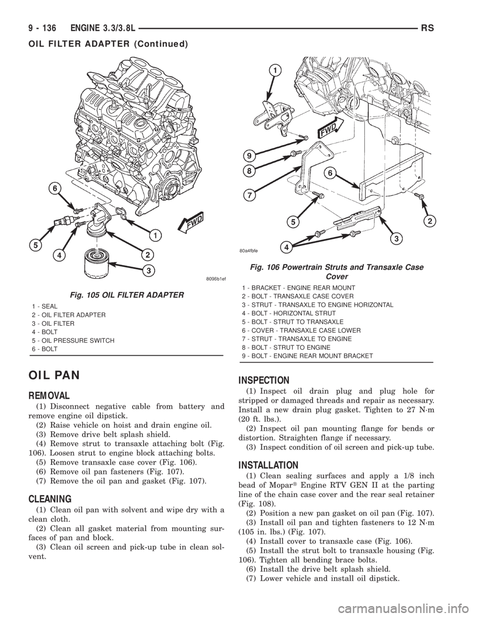
REMOVAL
(1) Disconnect negative cable from battery and
remove engine oil dipstick.
(2) Raise vehicle on hoist and drain engine oil.
(3) Remove drive belt splash shield.
(4) Remove strut to transaxle attaching bolt (Fig.
106). Loosen strut to engine block attaching bolts.
(5) Remove transaxle case cover (Fig. 106).
(6) Remove oil pan fasteners (Fig. 107).
(7) Remove the oil pan and gasket (Fig. 107).
CLEANING
(1) Clean oil pan with solvent and wipe dry with a
clean cloth.
(2) Clean all gasket material from mounting sur-
faces of pan and block.
(3) Clean oil screen and pick-up tube in clean sol-
vent.
INSPECTION
(1) Inspect oil drain plug and plug hole for
stripped or damaged threads and repair as necessary.
Install a new drain plug gasket. Tighten to 27 N´m
(20 ft. lbs.).
(2) Inspect oil pan mounting flange for bends or
distortion. Straighten flange if necessary.
(3) Inspect condition of oil screen and pick-up tube.
INSTALLATION
(1) Clean sealing surfaces and apply a 1/8 inch
bead of MopartEngine RTV GEN II at the parting
line of the chain case cover and the rear seal retainer
(Fig. 108).
(2) Position a new pan gasket on oil pan (Fig. 107).
(3) Install oil pan and tighten fasteners to 12 N´m
(105 in. lbs.) (Fig. 107).
(4) Install cover to transaxle case (Fig. 106).
(5) Install the strut bolt to transaxle housing (Fig.
106). Tighten all bending brace bolts.
(6) Install the drive belt splash shield.
(7) Lower vehicle and install oil dipstick.
Fig. 105 OIL FILTER ADAPTER
1 - SEAL
2 - OIL FILTER ADAPTER
3 - OIL FILTER
4 - BOLT
5 - OIL PRESSURE SWITCH
6 - BOLT
Fig. 106 Powertrain Struts and Transaxle Case
Cover
1 - BRACKET - ENGINE REAR MOUNT
2 - BOLT - TRANSAXLE CASE COVER
3 - STRUT - TRANSAXLE TO ENGINE HORIZONTAL
4 - BOLT - HORIZONTAL STRUT
5 - BOLT - STRUT TO TRANSAXLE
6 - COVER - TRANSAXLE CASE LOWER
7 - STRUT - TRANSAXLE TO ENGINE
8 - BOLT - STRUT TO ENGINE
9 - BOLT - ENGINE REAR MOUNT BRACKET
9 - 136 ENGINE 3.3/3.8LRS
OIL FILTER ADAPTER (Continued)
Page 2765 of 4284
between cylinder heads and houses the coolant ther-
mostat (Fig. 121).
The intake manifold utilizes a compact design with
very low restriction and outstanding flow balance.
This design allows the engine to perform with a wide
torque curve while increasing higher rpm horse-
power.
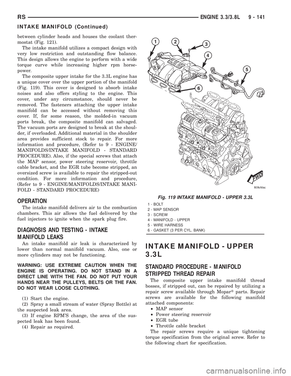
The composite upper intake for the 3.3L engine has
a unique cover over the upper portion of the manifold
(Fig. 119). This cover is designed to absorb intake
noises and also offers styling to the engine. This
cover, under any circumstance, should never be
removed. The fasteners attaching the upper intake
manifold can be accessed without removing this
cover. If, for some reason, the molded-in vacuum
ports break, the composite manifold can salvaged.
The vacuum ports are designed to break at the shoul-
der, if overloaded. Additional material in the shoulder
area provides sufficient stock to repair. For more
information and procedure, (Refer to 9 - ENGINE/
MANIFOLDS/INTAKE MANIFOLD - STANDARD
PROCEDURE). Also, if the special screws that attach
the MAP sensor, power steering reservoir, throttle
cable bracket, and the EGR tube become stripped, an
oversized screw is available to repair the stripped-out
condition. For more information and procedure,
(Refer to 9 - ENGINE/MANIFOLDS/INTAKE MANI-
FOLD - STANDARD PROCEDURE)
OPERATION
The intake manifold delivers air to the combustion
chambers. This air allows the fuel delivered by the
fuel injectors to ignite when the spark plug fire.
DIAGNOSIS AND TESTING - INTAKE
MANIFOLD LEAKS
An intake manifold air leak is characterized by
lower than normal manifold vacuum. Also, one or
more cylinders may not be functioning.
WARNING: USE EXTREME CAUTION WHEN THE
ENGINE IS OPERATING. DO NOT STAND IN A
DIRECT LINE WITH THE FAN. DO NOT PUT YOUR
HANDS NEAR THE PULLEYS, BELTS OR THE FAN.
DO NOT WEAR LOOSE CLOTHING.
(1) Start the engine.
(2) Spray a small stream of water (Spray Bottle) at
the suspected leak area.
(3) If engine RPM'S change, the area of the sus-
pected leak has been found.
(4) Repair as required.INTAKE MANIFOLD - UPPER
3.3L
STANDARD PROCEDURE - MANIFOLD
STRIPPED THREAD REPAIR
The composite upper intake manifold thread
bosses, if stripped out, can be repaired by utilizing a
repair screw available through Mopartparts. Repair
screws are available for the following manifold
attached components:
²MAP sensor
²Power steering reservoir
²EGR tube
²Throttle cable bracket
The repair screws require a unique tightening
torque specification from the original screw. Refer to
the following chart for specification.
Fig. 119 INTAKE MANIFOLD - UPPER 3.3L
1 - BOLT
2 - MAP SENSOR
3 - SCREW
4 - MANIFOLD - UPPER
5 - WIRE HARNESS
6 - GASKET (3 PER CYL. BANK)
RSENGINE 3.3/3.8L9 - 141
INTAKE MANIFOLD (Continued)
Page 2768 of 4284
CLEANING
(1) Discard gasket(s).
(2) Clean all sealing surfaces.
INSPECTION
Check manifold for:
²Damage and cracks.
²Mounting surface distortion by using a straight-
edge and thickness gauge.
INSTALLATION - 3.3L
(1) If the following components were removed from
manifold, install and tighten to specifications:
CAUTION: The special screws used for the compos-
ite manifold attached components must be installed
slowly using hand tools only. This requirement is to
prevent the melting of material that causes stripped
threads. If threads become stripped, an oversize
repair screw is available. For more information and
procedure (Refer to 9 - ENGINE/MANIFOLDS/IN-
TAKE MANIFOLD - STANDARD PROCEDURE).
²MAP sensor - 1.7 N´m (15 in. lbs.)
²Throttle cable bracket - 5.6 N´m (50 in. lbs.)
(2) Remove covering on lower intake manifold and
clean surfaces.
(3) Inspect manifold gasket condition. Gaskets can
be re-used, if not damaged. To replace, remove gasket
from upper manifold (Fig. 127). Position new gasket
in seal channel and press lightly in-place. Repeat
procedure for each gasket position.
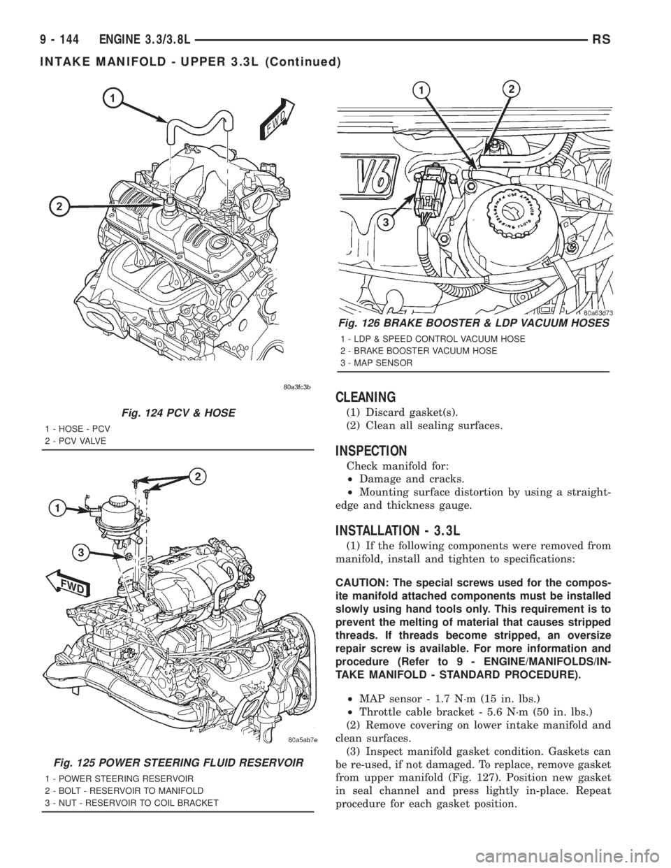
Fig. 124 PCV & HOSE
1 - HOSE - PCV
2 - P C V VA LV E
Fig. 125 POWER STEERING FLUID RESERVOIR
1 - POWER STEERING RESERVOIR
2 - BOLT - RESERVOIR TO MANIFOLD
3 - NUT - RESERVOIR TO COIL BRACKET
Fig. 126 BRAKE BOOSTER & LDP VACUUM HOSES
1 - LDP & SPEED CONTROL VACUUM HOSE
2 - BRAKE BOOSTER VACUUM HOSE
3 - MAP SENSOR
9 - 144 ENGINE 3.3/3.8LRS
INTAKE MANIFOLD - UPPER 3.3L (Continued)
Page 2787 of 4284
(24) Disconnect egr solenoid vacuum line at brake
booster check valve.
(25) Disconnect fuel injector, cam sensor, boost
pressure/intake air temp sensor, fuel rail high pres-
sure, and egr solenoid connectors (Fig. 9).
(26) Disconnect generator electrical connectors.
(27) Disconnect coolant temp sensor and glow plug
electrical connectors.
(28) Disconnect injection pump and A/C compres-
sor electrical connectors.
(29) Disconnect starter electrical connectors.
(30) Disconnect ground wires at engine block.
(31) Raise vehicle on hoist.
(32) Disconnect oil temp sensor, oil pressure sen-
sor, engine speed sensor, and vehicle speed sensor
electrical connector (Fig. 10).
(33) Remove front wheels.
(34) Remove the suspension cradle assembly (Refer
to 13 - FRAME & BUMPERS/FRAME/ENGINE
CRADLE CROSSMEMBER - REMOVAL).
(35) Remove both axle shaft assemblies (Refer to 3
- DIFFERENTIAL & DRIVELINE/HALF SHAFT -
REMOVAL).(36) Disconnect the clutch slave cylinder quick dis-
connect line (RHD only)(Refer to 6 - CLUTCH/SLAVE
CYLINDER - REMOVAL).
(37) Disconnect reverse lamp connector.
(38) Disconnect shifter cables at the tranmission
(Refer to 21 - TRANSMISSION/TRANSAXLE/MAN-
UAL/GEAR SHIFT CABLE - REMOVAL).
(39) Disconnect exhaust pipe from the turbo-
charger downpipe and reposition to right side of vehi-
cle.
(40) Disconnect cabin heater coolant line (Refer to
24 - HEATING & AIR CONDITIONING/CABIN
HEATER/HEATER UNIT - REMOVAL).
(41) Remove front engine mount bracket retaining
bolts from lower radiator support
(42) Lower vehicle. Evacuate the A/C system
(Refer to 24 - HEATING & AIR CONDITIONING/
PLUMBING/REFRIGERANT - STANDARD PROCE-
DURE).
(43) Disconnect the A/C lines at the A/C compres-
sor.
(44) Disconnect the fuel supply and return lines.
(45) Position engine cradle under engine and lower
vehicle over cradle.
(46) Remove right engine mount bolts.
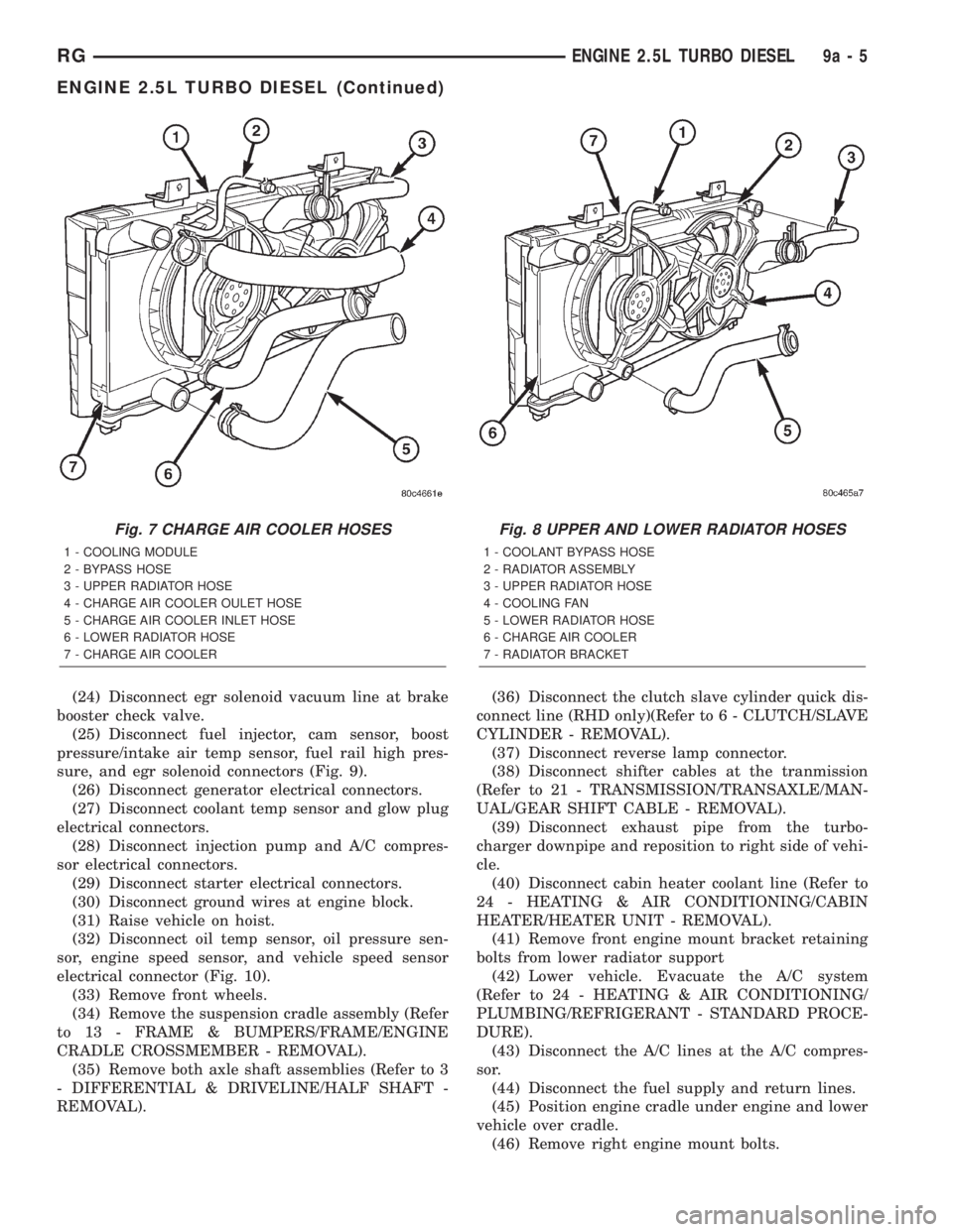
Fig. 7 CHARGE AIR COOLER HOSES
1 - COOLING MODULE
2 - BYPASS HOSE
3 - UPPER RADIATOR HOSE
4 - CHARGE AIR COOLER OULET HOSE
5 - CHARGE AIR COOLER INLET HOSE
6 - LOWER RADIATOR HOSE
7 - CHARGE AIR COOLER
Fig. 8 UPPER AND LOWER RADIATOR HOSES
1 - COOLANT BYPASS HOSE
2 - RADIATOR ASSEMBLY
3 - UPPER RADIATOR HOSE
4 - COOLING FAN
5 - LOWER RADIATOR HOSE
6 - CHARGE AIR COOLER
7 - RADIATOR BRACKET
RGENGINE 2.5L TURBO DIESEL9a-5
ENGINE 2.5L TURBO DIESEL (Continued)