2001 CHRYSLER VOYAGER air condition
[x] Cancel search: air conditionPage 2931 of 4284
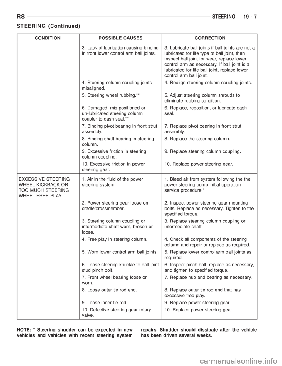
CONDITION POSSIBLE CAUSES CORRECTION
3. Lack of lubrication causing binding
in front lower control arm ball joints.3. Lubricate ball joints if ball joints are not a
lubricated for life type of ball joint, then
inspect ball joint for wear, replace lower
control arm as necessary. If ball joint is a
lubricated for life ball joint, replace lower
control arm ball joint.
4. Steering column coupling joints
misaligned.4. Realign steering column coupling joints.
5. Steering wheel rubbing.** 5. Adjust steering column shrouds to
eliminate rubbing condition.
6. Damaged, mis-positioned or
un-lubricated steering column
coupler to dash seal.**6. Replace, reposition, or lubricate dash
seal.
7. Binding pivot bearing in front strut
assembly.7. Replace pivot bearing in front strut
assembly.
8. Binding shaft bearing in steering
column.8. Replace the steering column.
9. Excessive friction in steering
column coupling.9. Replace steering column coupling.
10. Excessive friction in power
steering gear.10. Replace power steering gear.
EXCESSIVE STEERING
WHEEL KICKBACK OR
TOO MUCH STEERING
WHEEL FREE PLAY.1. Air in the fluid of the power
steering system.1. Bleed air from system following the the
power steering pump initial operation
service procedure.*
2. Power steering gear loose on
cradle/crossmember.2. Inspect power steering gear mounting
bolts. Replace as necessary. Tighten to the
specified torque.
3. Steering column coupling or
intermediate shaft worn, broken or
loose.3. Replace steering column coupling or
intermediate shaft.
4. Free play in steering column. 4. Check all components of the steering
column and repair or replace as required.
5. Worn lower control arm ball joints. 5. Replace lower control arm ball joints as
required.
6. Loose steering knuckle-to-ball joint
stud pinch bolt.6. Inspect pinch bolt, replace as necessary,
and tighten to specified torque.
7. Front wheel bearing loose or
worn.7. Replace hub and bearing as necessary.
8. Loose outer tie rod end. 8. Replace outer tie rod end that has
excessive free play.
9. Loose inner tie rod. 9. Replace power steering gear.
10. Defective steering gear rotary
valve.10. Replace power steering gear.
NOTE: * Steering shudder can be expected in new
vehicles and vehicles with recent steering systemrepairs. Shudder should dissipate after the vehicle
has been driven several weeks.
RSSTEERING19-7
STEERING (Continued)
Page 2932 of 4284
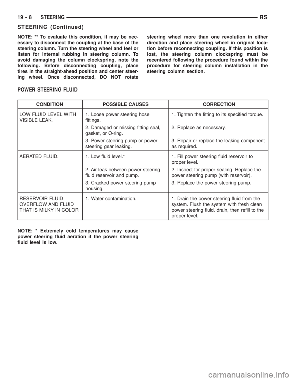
NOTE: ** To evaluate this condition, it may be nec-
essary to disconnect the coupling at the base of the
steering column. Turn the steering wheel and feel or
listen for internal rubbing in steering column. To
avoid damaging the column clockspring, note the
following. Before disconnecting coupling, place
tires in the straight-ahead position and center steer-
ing wheel. Once disconnected, DO NOT rotatesteering wheel more than one revolution in either
direction and place steering wheel in original loca-
tion before reconnecting coupling. If this position is
lost, the steering column clockspring must be
recentered following the procedure found within the
procedure for steering column installation in the
steering column section.
POWER STEERING FLUID
CONDITION POSSIBLE CAUSES CORRECTION
LOW FLUID LEVEL WITH
VISIBLE LEAK.1. Loose power steering hose
fittings.1. Tighten the fitting to its specified torque.
2. Damaged or missing fitting seal,
gasket, or O-ring.2. Replace as necessary.
3. Power steering pump or power
steering gear leaking.3. Repair or replace the leaking component
as required.
AERATED FLUID. 1. Low fluid level.* 1. Fill power steering fluid reservoir to
proper level.
2. Air leak between power steering
fluid reservoir and pump.2. Inspect for proper sealing. Replace the
power steering pump (with reservoir).
3. Cracked power steering pump
housing.3. Replace the power steering pump.
RESERVOIR FLUID
OVERFLOW AND FLUID
THAT IS MILKY IN COLOR1. Water contamination. 1. Drain the power steering fluid from the
system. Flush the system with fresh clean
power steering fluid, drain, then refill to the
proper level.
NOTE: * Extremely cold temperatures may cause
power steering fluid aeration if the power steering
fluid level is low.
19 - 8 STEERINGRS
STEERING (Continued)
Page 2936 of 4284
WARNING: SAFETY GOGGLES SHOULD BE WORN
AT ALL TIMES WHEN WORKING ON STEERING
COLUMNS.
CAUTION: Disconnect negative (ground) cable from
the battery before servicing any column compo-
nent.
CAUTION: Do not attempt to remove the pivot pins
to disassemble the tilting mechanism. Damage will
occur.
DIAGNOSIS AND TESTING
For diagnosis of conditions relating to the steering
column (Refer to 19 - STEERING - DIAGNOSIS AND
TESTING) and (Refer to 19 - STEERING - DIAGNO-
SIS AND TESTING).
REMOVAL
To service the steering wheel components or the
airbag (Refer to 8 - ELECTRICAL/RESTRAINTS/
DRIVER AIRBAG - REMOVAL). Follow all WARN-
INGS AND CAUTIONS.
(1) Make sure the front wheels of the vehicle are
in the STRAIGHT AHEAD position before beginning
the column removal procedure.
(2) Disconnect negative (ground) cable from the
battery and isolate cable from battery terminal.
(3) Remove the lower shroud (Refer to 19 -
STEERING/COLUMN/LOWER SHROUD - REMOV-
AL).
(4) Remove the traction off switch.
(5) Remove the upper shroud.
(6) Remove the cluster trim bezel (Refer to 23 -
BODY/INSTRUMENT PANEL/CLUSTER BEZEL -
REMOVAL).(7) Remove the knee blocker (Refer to 23 - BODY/
INSTRUMENT PANEL/STEERING COLUMN
OPENING COVER - REMOVAL).
(8) Remove the parking brake handle link.
(9) Remove the knee blocker reinforcement (Refer
to 23 - BODY/INSTRUMENT PANEL/KNEE
BLOCKER - REMOVAL).
(10) Remove the airbag (Refer to 8 - ELECTRI-
CAL/RESTRAINTS/DRIVER AIRBAG - REMOVAL).
(11) Remove the steering wheel retaining nut.
(12) Remove the vibration damper weight.
(13) Remove the steering wheel (Refer to 19 -
STEERING/COLUMN/STEERING WHEEL -
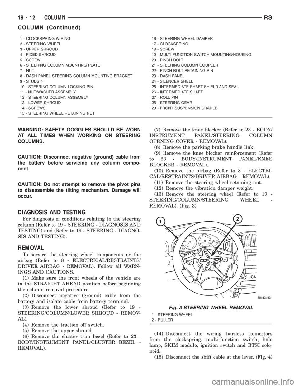
REMOVAL). (Fig. 3)
(14) Disconnect the wiring harness connectors
from the clockspring, multi-function switch, halo
lamp, SKIM module, ignition switch and BTSI sole-
noid.
(15) Disconnect the shift cable at the lever. (Fig. 4)
1 - CLOCKSPRING WIRING
2 - STEERING WHEEL
3 - UPPER SHROUD
4 - FIXED SHROUD
5 - SCREW
6 - STEERING COLUMN MOUNTING PLATE
7 - NUT
8 - DASH PANEL STEERING COLUMN MOUNTING BRACKET
9 - STUDS 4
10 - STEERING COLUMN LOCKING PIN
11 - NUT/WASHER ASSEMBLY
12 - STEERING COLUMN ASSEMBLY
13 - LOWER SHROUD
14 - SCREWS
15 - STEERING WHEEL RETAINING NUT16 - STEERING WHEEL DAMPER
17 - CLOCKSPRING
18 - SCREW
19 - MULTI-FUNCTION SWITCH MOUNTING/HOUSING
20 - PINCH BOLT
21 - STEERING COLUMN COUPLER
22 - PINCH BOLT RETAINING PIN
23 - DASH PANEL
24 - SILENCER SHELL
25 - INTERMEDIATE SHAFT SHIELD AND SEAL
26 - INTERMEDIATE SHAFT
27 - ROLL PIN
28 - STEERING GEAR
29 - FRONT SUSPENSION CRADLE
Fig. 3 STEERING WHEEL REMOVAL
1 - STEERING WHEEL
2 - PULLER
19 - 12 COLUMNRS
COLUMN (Continued)
Page 2985 of 4284
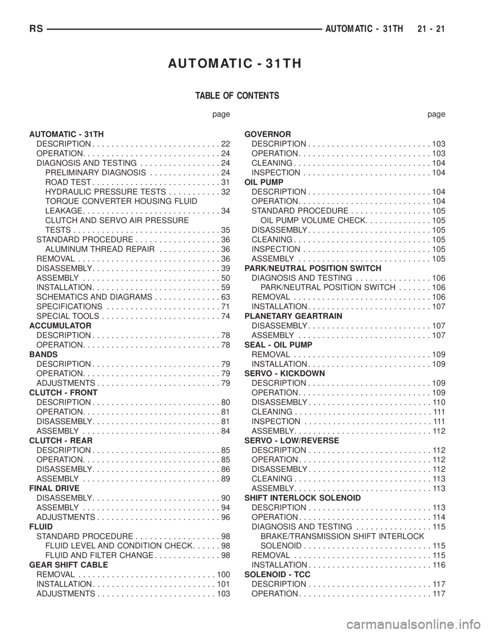
AUTOMATIC - 31TH
TABLE OF CONTENTS
page page
AUTOMATIC - 31TH
DESCRIPTION...........................22
OPERATION.............................24
DIAGNOSIS AND TESTING.................24
PRELIMINARY DIAGNOSIS...............24
ROAD TEST...........................31
HYDRAULIC PRESSURE TESTS...........32
TORQUE CONVERTER HOUSING FLUID
LEAKAGE.............................34
CLUTCH AND SERVO AIR PRESSURE
TESTS...............................35
STANDARD PROCEDURE..................36
ALUMINUM THREAD REPAIR.............36
REMOVAL..............................36
DISASSEMBLY...........................39
ASSEMBLY.............................50
INSTALLATION...........................59
SCHEMATICS AND DIAGRAMS..............63
SPECIFICATIONS........................71
SPECIAL TOOLS.........................74
ACCUMULATOR
DESCRIPTION...........................78
OPERATION.............................78
BANDS
DESCRIPTION...........................79
OPERATION.............................79
ADJUSTMENTS..........................79
CLUTCH - FRONT
DESCRIPTION...........................80
OPERATION.............................81
DISASSEMBLY...........................81
ASSEMBLY.............................84
CLUTCH - REAR
DESCRIPTION...........................85
OPERATION.............................85
DISASSEMBLY...........................86
ASSEMBLY.............................89
FINAL DRIVE
DISASSEMBLY...........................90
ASSEMBLY.............................94
ADJUSTMENTS..........................96
FLUID
STANDARD PROCEDURE..................98
FLUID LEVEL AND CONDITION CHECK......98
FLUID AND FILTER CHANGE..............98
GEAR SHIFT CABLE
REMOVAL.............................100
INSTALLATION..........................101
ADJUSTMENTS.........................103GOVERNOR
DESCRIPTION..........................103
OPERATION............................103
CLEANING.............................104
INSPECTION...........................104
OIL PUMP
DESCRIPTION..........................104
OPERATION............................104
STANDARD PROCEDURE.................105
OIL PUMP VOLUME CHECK..............105
DISASSEMBLY..........................105
CLEANING.............................105
INSPECTION...........................105
ASSEMBLY............................105
PARK/NEUTRAL POSITION SWITCH
DIAGNOSIS AND TESTING................106
PARK/NEUTRAL POSITION SWITCH.......106
REMOVAL.............................106
INSTALLATION..........................107
PLANETARY GEARTRAIN
DISASSEMBLY..........................107
ASSEMBLY............................107
SEAL - OIL PUMP
REMOVAL.............................109
INSTALLATION..........................109
SERVO - KICKDOWN
DESCRIPTION..........................109
OPERATION............................109
DISASSEMBLY..........................110
CLEANING.............................111
INSPECTION...........................111
ASSEMBLY.............................112
SERVO - LOW/REVERSE
DESCRIPTION..........................112
OPERATION............................112
DISASSEMBLY..........................112
CLEANING.............................113
ASSEMBLY.............................113
SHIFT INTERLOCK SOLENOID
DESCRIPTION..........................113
OPERATION............................114
DIAGNOSIS AND TESTING................115
BRAKE/TRANSMISSION SHIFT INTERLOCK
SOLENOID...........................115
REMOVAL.............................115
INSTALLATION..........................116
SOLENOID - TCC
DESCRIPTION..........................117
OPERATION............................117
RSAUTOMATIC - 31TH21-21
Page 2988 of 4284
OPERATION
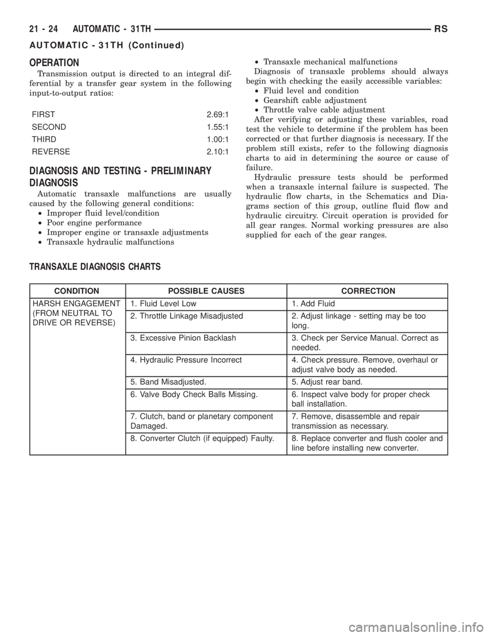
Transmission output is directed to an integral dif-
ferential by a transfer gear system in the following
input-to-output ratios:
FIRST 2.69:1
SECOND 1.55:1
THIRD 1.00:1
REVERSE 2.10:1
DIAGNOSIS AND TESTING - PRELIMINARY
DIAGNOSIS
Automatic transaxle malfunctions are usually
caused by the following general conditions:
²Improper fluid level/condition
²Poor engine performance
²Improper engine or transaxle adjustments
²Transaxle hydraulic malfunctions²Transaxle mechanical malfunctions
Diagnosis of transaxle problems should always
begin with checking the easily accessible variables:
²Fluid level and condition
²Gearshift cable adjustment
²Throttle valve cable adjustment
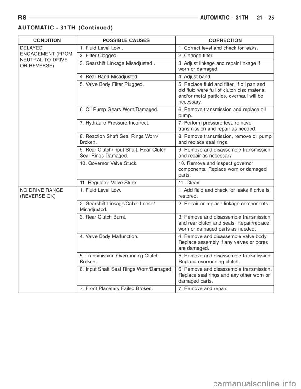
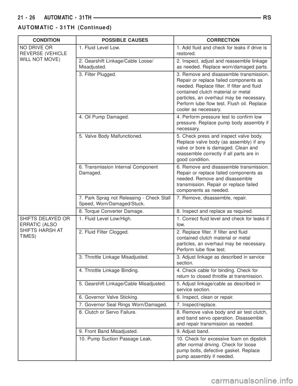
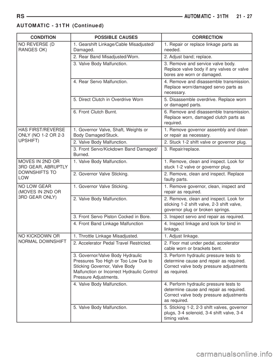
After verifying or adjusting these variables, road
test the vehicle to determine if the problem has been
corrected or that further diagnosis is necessary. If the
problem still exists, refer to the following diagnosis
charts to aid in determining the source or cause of
failure.
Hydraulic pressure tests should be performed
when a transaxle internal failure is suspected. The
hydraulic flow charts, in the Schematics and Dia-
grams section of this group, outline fluid flow and
hydraulic circuitry. Circuit operation is provided for
all gear ranges. Normal working pressures are also
supplied for each of the gear ranges.
TRANSAXLE DIAGNOSIS CHARTS
CONDITION POSSIBLE CAUSES CORRECTION
HARSH ENGAGEMENT
(FROM NEUTRAL TO
DRIVE OR REVERSE)1. Fluid Level Low 1. Add Fluid
2. Throttle Linkage Misadjusted 2. Adjust linkage - setting may be too
long.
3. Excessive Pinion Backlash 3. Check per Service Manual. Correct as
needed.
4. Hydraulic Pressure Incorrect 4. Check pressure. Remove, overhaul or
adjust valve body as needed.
5. Band Misadjusted. 5. Adjust rear band.
6. Valve Body Check Balls Missing. 6. Inspect valve body for proper check
ball installation.
7. Clutch, band or planetary component
Damaged.7. Remove, disassemble and repair
transmission as necessary.
8. Converter Clutch (if equipped) Faulty. 8. Replace converter and flush cooler and
line before installing new converter.
21 - 24 AUTOMATIC - 31THRS
AUTOMATIC - 31TH (Continued)
Page 2989 of 4284
CONDITION POSSIBLE CAUSES CORRECTION
DELAYED
ENGAGEMENT (FROM
NEUTRAL TO DRIVE
OR REVERSE)1. Fluid Level Low . 1. Correct level and check for leaks.
2. Filter Clogged. 2. Change filter.
3. Gearshift Linkage Misadjusted . 3. Adjust linkage and repair linkage if
worn or damaged.
4. Rear Band Misadjusted. 4. Adjust band.
5. Valve Body Filter Plugged. 5. Replace fluid and filter. If oil pan and
old fluid were full of clutch disc material
and/or metal particles, overhaul will be
necessary.
6. Oil Pump Gears Worn/Damaged. 6. Remove transmission and replace oil
pump.
7. Hydraulic Pressure Incorrect. 7. Perform pressure test, remove
transmission and repair as needed.
8. Reaction Shaft Seal Rings Worn/
Broken.8. Remove transmission, remove oil pump
and replace seal rings.
9. Rear Clutch/Input Shaft, Rear Clutch
Seal Rings Damaged.9. Remove and disassemble transmission
and repair as necessary.
10. Governor Valve Stuck. 10. Remove and inspect governor
components. Replace worn or damaged
parts.
11. Regulator Valve Stuck. 11. Clean.
NO DRIVE RANGE
(REVERSE OK)1. Fluid Level Low. 1. Add fluid and check for leaks if drive is
restored.
2. Gearshift Linkage/Cable Loose/
Misadjusted.2. Repair or replace linkage components.
3. Rear Clutch Burnt. 3. Remove and disassemble transmission
and rear clutch and seals. Repair/replace
worn or damaged parts as needed.
4. Valve Body Malfunction. 4. Remove and disassemble valve body.
Replace assembly if any valves or bores
are damaged.
5. Transmission Overrunning Clutch
Broken.5. Remove and disassemble transmission.
Replace overrunning clutch.
6. Input Shaft Seal Rings Worn/Damaged. 6. Remove and disassemble transmission.
Replace seal rings and any other worn or
damaged parts.
7. Front Planetary Failed Broken. 7. Remove and repair.
RSAUTOMATIC - 31TH21-25
AUTOMATIC - 31TH (Continued)
Page 2990 of 4284
CONDITION POSSIBLE CAUSES CORRECTION
NO DRIVE OR
REVERSE (VEHICLE
WILL NOT MOVE)1. Fluid Level Low. 1. Add fluid and check for leaks if drive is
restored.
2. Gearshift Linkage/Cable Loose/
Misadjusted.2. Inspect, adjust and reassemble linkage
as needed. Replace worn/damaged parts.
3. Filter Plugged. 3. Remove and disassemble transmission.
Repair or replace failed components as
needed. Replace filter. If filter and fluid
contained clutch material or metal
particles, an overhaul may be necessary.
Perform lube flow test. Flush oil. Replace
cooler as necessary.
4. Oil Pump Damaged. 4. Perform pressure test to confirm low
pressure. Replace pump body assembly if
necessary.
5. Valve Body Malfunctioned. 5. Check press and inspect valve body.
Replace valve body (as assembly) if any
valve or bore is damaged. Clean and
reassemble correctly if all parts are in
good condition.
6. Transmission Internal Component
Damaged.6. Remove and disassemble transmission.
Repair or replace failed components as
needed. Remove and disassemble
transmission. Repair or replace failed
components as needed.
7. Park Sprag not Releasing - Check Stall
Speed, Worn/Damaged/Stuck.7. Remove, disassemble, repair.
8. Torque Converter Damage. 8. Inspect and replace as required.
SHIFTS DELAYED OR
ERRATIC (ALSO
SHIFTS HARSH AT
TIMES)1. Fluid Level Low/High. 1. Correct fluid level and check for leaks if
low.
2. Fluid Filter Clogged. 2. Replace filter. If filter and fluid
contained clutch material or metal
particles, an overhaul may be necessary.
Perform lube flow test.
3. Throttle Linkage Misadjusted. 3. Adjust linkage as described in service
section.
4. Throttle Linkage Binding. 4. Check cable for binding. Check for
return to closed throttle at transmission.
5. Gearshift Linkage/Cable Misadjusted. 5. Adjust linkage/cable as described in
service section.
6. Governor Valve Sticking. 6. Inspect, clean or repair.
7. Governor Seal Rings Worn/Damaged. 7. Inspect/replace.
8. Clutch or Servo Failure. 8. Remove valve body and air test clutch,
and band servo operation. Disassemble
and repair transmission as needed.
9. Front Band Misadjusted. 9. Adjust band.
10. Pump Suction Passage Leak. 10. Check for excessive foam on dipstick
after normal driving. Check for loose
pump bolts, defective gasket. Replace
pump assembly if needed.
21 - 26 AUTOMATIC - 31THRS
AUTOMATIC - 31TH (Continued)
Page 2991 of 4284
CONDITION POSSIBLE CAUSES CORRECTION
NO REVERSE (D
RANGES OK)1. Gearshift Linkage/Cable Misadjusted/
Damaged.1. Repair or replace linkage parts as
needed.
2. Rear Band Misadjusted/Worn. 2. Adjust band; replace.
3. Valve Body Malfunction. 3. Remove and service valve body.
Replace valve body if any valves or valve
bores are worn or damaged.
4. Rear Servo Malfunction. 4. Remove and disassemble transmission.
Replace worn/damaged servo parts as
necessary.
5. Direct Clutch in Overdrive Worn 5. Disassemble overdrive. Replace worn
or damaged parts.
6. Front Clutch Burnt. 6. Remove and disassemble transmission.
Replace worn, damaged clutch parts as
required.
HAS FIRST/REVERSE
ONLY (NO 1-2 OR 2-3
UPSHIFT)1. Governor Valve, Shaft, Weights or
Body Damaged/Stuck.1. Remove governor assembly and clean
or repair as necessary.
2. Valve Body Malfunction. 2. Stuck 1-2 shift valve or governor plug.
3. Front Servo/Kickdown Band Damaged/
Burned.3. Repair/replace.
MOVES IN 2ND OR
3RD GEAR, ABRUPTLY
DOWNSHIFTS TO
LOW1. Valve Body Malfunction. 1. Remove, clean and inspect. Look for
stuck 1-2 valve or governor plug.
2. Governor Valve Sticking. 2. Remove, clean and inspect. Replace
faulty parts.
NO LOW GEAR
(MOVES IN 2ND OR
3RD GEAR ONLY)1. Governor Valve Sticking. 1. Remove governor, clean, inspect and
repair as required.
2. Valve Body Malfunction. 2. Remove, clean and inspect. Look for
sticking 1-2 shift valve, 2-3 shift valve,
governor plug or broken springs.
3. Front Servo Piston Cocked in Bore. 3. Inspect servo and repair as required.
4. Front Band Linkage Malfunction 4. Inspect linkage and look for bind in
linkage.
NO KICKDOWN OR
NORMAL DOWNSHIFT1. Throttle Linkage Misadjusted. 1. Adjust linkage.
2. Accelerator Pedal Travel Restricted. 2. Floor mat under pedal, accelerator
cable worn or brackets bent.
3. Governor/Valve Body Hydraulic
Pressures Too High or Too Low Due to
Sticking Governor, Valve Body
Malfunction or Incorrect Hydraulic Control
Pressure Adjustments.3. Perform hydraulic pressure tests to
determine cause and repair as required.
Correct valve body pressure adjustments
as required.
4. Valve Body Malfunction. 4. Perform hydraulic pressure tests to
determine cause and repair as required.
Correct valve body pressure adjustments
as required.
5. Valve Body Malfunction. 5. Sticking 1-2, 2-3 shift valves, governor
plugs, 3-4 solenoid, 3-4 shift valve, 3-4
timing valve.
RSAUTOMATIC - 31TH21-27
AUTOMATIC - 31TH (Continued)