2001 CHRYSLER VOYAGER air condition
[x] Cancel search: air conditionPage 2992 of 4284
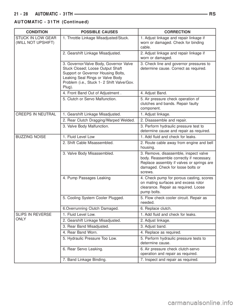
CONDITION POSSIBLE CAUSES CORRECTION
STUCK IN LOW GEAR
(WILL NOT UPSHIFT)1. Throttle Linkage Misadjusted/Stuck. 1. Adjust linkage and repair linkage if
worn or damaged. Check for binding
cable.
2. Gearshift Linkage Misadjusted. 2. Adjust linkage and repair linkage if
worn or damaged.
3. Governor/Valve Body, Governor Valve
Stuck Closed; Loose Output Shaft
Support or Governor Housing Bolts,
Leaking Seal Rings or Valve Body
Problem (i.e., Stuck 1- 2 Shift Valve/Gov.
Plug).3. Check line and governor pressures to
determine cause. Correct as required.
4. Front Band Out of Adjustment . 4. Adjust Band.
5. Clutch or Servo Malfunction. 5. Air pressure check operation of
clutches and bands. Repair faulty
component.
CREEPS IN NEUTRAL 1. Gearshift Linkage Misadjusted. 1. Adjust linkage.
2. Rear Clutch Dragging/Warped Welded. 2. Disassemble and repair.
3. Valve Body Malfunction. 3. Perform hydraulic pressure test to
determine cause and repair as required.
BUZZING NOISE 1. Fluid Level Low 1. Add fluid and check for leaks.
2. Shift Cable Misassembled. 2. Route cable away from engine and bell
housing.
3. Valve Body Misassembled. 3. Remove, disassemble, inspect valve
body. Reassemble correctly if necessary.
Replace assembly if valves or springs are
damaged. Check for loose bolts or
screws.
4. Pump Passages Leaking 4. Check pump for porous casting, scores
on mating surfaces and excess rotor
clearance. Repair as required. Loose
pump bolts.
5. Cooling System Cooler Plugged. 5. Flow check cooler circuit. Repair as
needed.
6.Overrunning Clutch Damaged. 6. Replace clutch.
SLIPS IN REVERSE
ONLY1. Fluid Level Low. 1. Add fluid and check for leaks.
2. Gearshift Linkage Misadjusted. 2. Adjust linkage.
3. Rear Band Misadjusted. 3. Adjust band.
4. Rear Band Worn. 4. Replace as required.
5. Hydraulic Pressure Too Low. 5. Perform hydraulic pressure tests to
determine cause.
6. Rear Servo Leaking. 6. Air pressure check clutch-servo
operation and repair as required.
7. Band Linkage Binding. 7. Inspect and repair as required.
21 - 28 AUTOMATIC - 31THRS
AUTOMATIC - 31TH (Continued)
Page 2993 of 4284
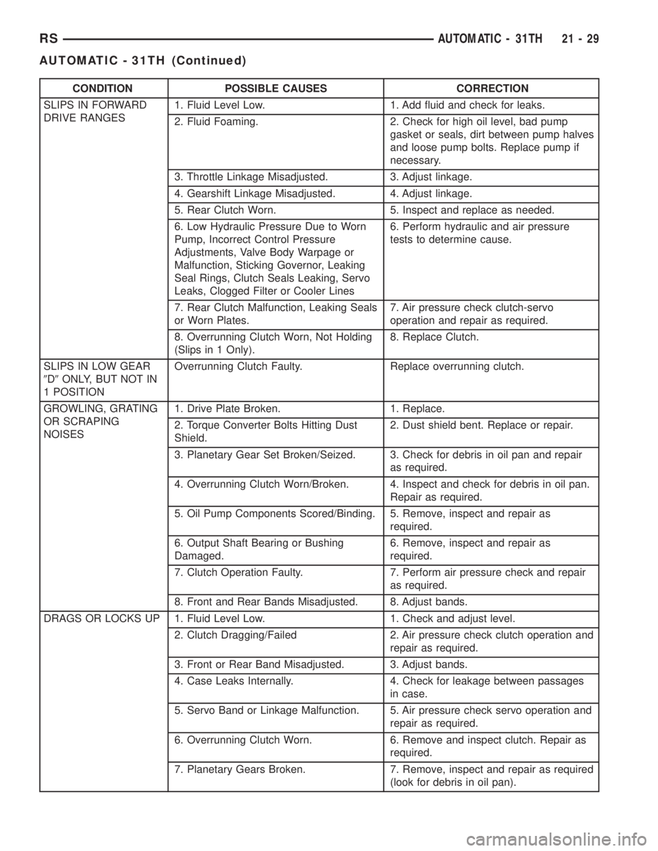
CONDITION POSSIBLE CAUSES CORRECTION
SLIPS IN FORWARD
DRIVE RANGES1. Fluid Level Low. 1. Add fluid and check for leaks.
2. Fluid Foaming. 2. Check for high oil level, bad pump
gasket or seals, dirt between pump halves
and loose pump bolts. Replace pump if
necessary.
3. Throttle Linkage Misadjusted. 3. Adjust linkage.
4. Gearshift Linkage Misadjusted. 4. Adjust linkage.
5. Rear Clutch Worn. 5. Inspect and replace as needed.
6. Low Hydraulic Pressure Due to Worn
Pump, Incorrect Control Pressure
Adjustments, Valve Body Warpage or
Malfunction, Sticking Governor, Leaking
Seal Rings, Clutch Seals Leaking, Servo
Leaks, Clogged Filter or Cooler Lines6. Perform hydraulic and air pressure
tests to determine cause.
7. Rear Clutch Malfunction, Leaking Seals
or Worn Plates.7. Air pressure check clutch-servo
operation and repair as required.
8. Overrunning Clutch Worn, Not Holding
(Slips in 1 Only).8. Replace Clutch.
SLIPS IN LOW GEAR
9D9ONLY, BUT NOT IN
1 POSITIONOverrunning Clutch Faulty. Replace overrunning clutch.
GROWLING, GRATING
OR SCRAPING
NOISES1. Drive Plate Broken. 1. Replace.
2. Torque Converter Bolts Hitting Dust
Shield.2. Dust shield bent. Replace or repair.
3. Planetary Gear Set Broken/Seized. 3. Check for debris in oil pan and repair
as required.
4. Overrunning Clutch Worn/Broken. 4. Inspect and check for debris in oil pan.
Repair as required.
5. Oil Pump Components Scored/Binding. 5. Remove, inspect and repair as
required.
6. Output Shaft Bearing or Bushing
Damaged.6. Remove, inspect and repair as
required.
7. Clutch Operation Faulty. 7. Perform air pressure check and repair
as required.
8. Front and Rear Bands Misadjusted. 8. Adjust bands.
DRAGS OR LOCKS UP 1. Fluid Level Low. 1. Check and adjust level.
2. Clutch Dragging/Failed 2. Air pressure check clutch operation and
repair as required.
3. Front or Rear Band Misadjusted. 3. Adjust bands.
4. Case Leaks Internally. 4. Check for leakage between passages
in case.
5. Servo Band or Linkage Malfunction. 5. Air pressure check servo operation and
repair as required.
6. Overrunning Clutch Worn. 6. Remove and inspect clutch. Repair as
required.
7. Planetary Gears Broken. 7. Remove, inspect and repair as required
(look for debris in oil pan).
RSAUTOMATIC - 31TH21-29
AUTOMATIC - 31TH (Continued)
Page 2994 of 4284
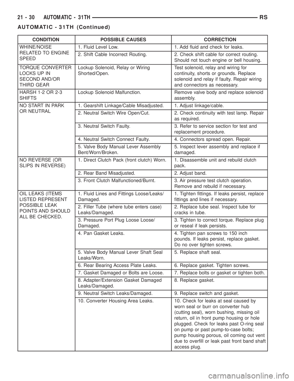
CONDITION POSSIBLE CAUSES CORRECTION
WHINE/NOISE
RELATED TO ENGINE
SPEED1. Fluid Level Low. 1. Add fluid and check for leaks.
2. Shift Cable Incorrect Routing. 2. Check shift cable for correct routing.
Should not touch engine or bell housing.
TORQUE CONVERTER
LOCKS UP IN
SECOND AND/OR
THIRD GEARLockup Solenoid, Relay or Wiring
Shorted/Open.Test solenoid, relay and wiring for
continuity, shorts or grounds. Replace
solenoid and relay if faulty. Repair wiring
and connectors as necessary.
HARSH 1-2 OR 2-3
SHIFTSLockup Solenoid Malfunction. Remove valve body and replace solenoid
assembly.
NO START IN PARK
OR NEUTRAL1. Gearshift Linkage/Cable Misadjusted. 1. Adjust linkage/cable.
2. Neutral Switch Wire Open/Cut. 2. Check continuity with test lamp. Repair
as required.
3. Neutral Switch Faulty. 3. Refer to service section for test and
replacement procedure.
4. Neutral Switch Connect Faulty. 4. Connectors spread open. Repair.
5. Valve Body Manual Lever Assembly
Bent/Worn/Broken.5. Inspect lever assembly and replace if
damaged.
NO REVERSE (OR
SLIPS IN REVERSE)1. Direct Clutch Pack (front clutch) Worn. 1. Disassemble unit and rebuild clutch
pack.
2. Rear Band Misadjusted. 2. Adjust band.
3. Front Clutch Malfunctioned/Burnt. 3. Air pressure test clutch operation.
Remove and rebuild if necessary.
OIL LEAKS (ITEMS
LISTED REPRESENT
POSSIBLE LEAK
POINTS AND SHOULD
ALL BE CHECKED.1. Fluid Lines and Fittings Loose/Leaks/
Damaged.1. Tighten fittings. If leaks persist, replace
fittings and lines if necessary.
2. Filler Tube (where tube enters case)
Leaks/Damaged.2. Replace tube seal. Inspect tube for
cracks in tube.
3. Pressure Port Plug Loose Loose/
Damaged.3. Tighten to correct torque. Replace plug
or reseal if leak persists.
4. Pan Gasket Leaks. 4. Tighten pan screws to 150 inch
pounds. If leaks persist, replace gasket.
Do no over tighten screws.
5. Valve Body Manual Lever Shaft Seal
Leaks/Worn.5. Replace shaft seal.
6. Rear Bearing Access Plate Leaks. 6. Replace gasket. Tighten screws.
7. Gasket Damaged or Bolts are Loose. 7. Replace bolts or gasket or tighten both.
8. Adapter/Extension Gasket Damaged
Leaks/Damaged.8. Replace gasket.
9. Neutral Switch Leaks/Damaged. 9. Replace switch and gasket.
10. Converter Housing Area Leaks. 10. Check for leaks at seal caused by
worn seal or burr on converter hub
(cutting seal), worn bushing, missing oil
return, oil in front pump housing or hole
plugged. Check for leaks past O-ring seal
on pump or past pump-to-case bolts;
pump housing porous, oil coming out vent
due to overfill or leak past front band shaft
access plug.
21 - 30 AUTOMATIC - 31THRS
AUTOMATIC - 31TH (Continued)
Page 2999 of 4284
DIAGNOSIS AND TESTING - CLUTCH AND
SERVO AIR PRESSURE TESTS
A no drive condition might exist even with correct
fluid pressure, because of inoperative clutches or
bands. The inoperative units, clutches, bands, and
servos can be located through a series of tests. This
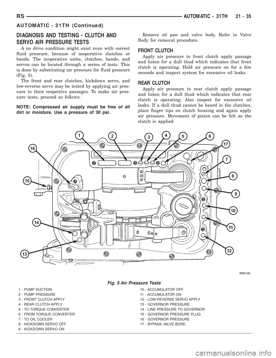
is done by substituting air pressure for fluid pressure
(Fig. 5).
The front and rear clutches, kickdown servo, and
low-reverse servo may be tested by applying air pres-
sure to their respective passages. To make air pres-
sure tests, proceed as follows:
NOTE: Compressed air supply must be free of all
dirt or moisture. Use a pressure of 30 psi.Remove oil pan and valve body. Refer to Valve
Body for removal procedure.FRONT CLUTCH
Apply air pressure to front clutch apply passage
and listen for a dull thud which indicates that front
clutch is operating. Hold air pressure on for a few
seconds and inspect system for excessive oil leaks.
REAR CLUTCH
Apply air pressure to rear clutch apply passage
and listen for a dull thud which indicates that rear
clutch is operating. Also inspect for excessive oil
leaks. If a dull thud cannot be heard in the clutches,
place finger tips on clutch housing and again apply
air pressure. Movement of piston can be felt as the
clutch is applied.
Fig. 5 Air Pressure Tests
1 - PUMP SUCTION
2 - PUMP PRESSURE
3 - FRONT CLUTCH APPLY
4 - REAR CLUTCH APPLY
5 - TO TORQUE CONVERTER
6 - FROM TORQUE CONVERTER
7 - TO OIL COOLER
8 - KICKDOWN SERVO OFF
9 - KICKDOWN SERVO ON10 - ACCUMULATOR OFF
11 - ACCUMULATOR ON
12 - LOW-REVERSE SERVO APPLY
13 - GOVERNOR PRESSURE
14 - LINE PRESSURE TO GOVERNOR
15 - GOVERNOR PRESSURE PLUG
16 - GOVERNOR PRESSURE
17 - BYPASS VALVE BORE
RSAUTOMATIC - 31TH21-35
AUTOMATIC - 31TH (Continued)
Page 3062 of 4284
FLUID
STANDARD PROCEDURE - FLUID LEVEL AND
CONDITION CHECK
NOTE: The transmission and differential sump have
a common oil sump with a communicating opening
between the two.
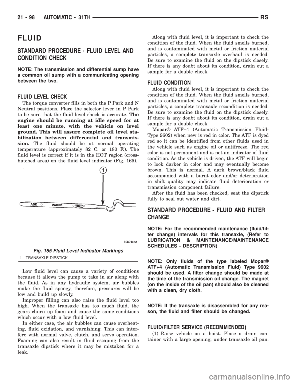
FLUID LEVEL CHECK
The torque converter fills in both the P Park and N
Neutral positions. Place the selector lever in P Park
to be sure that the fluid level check is accurate.The
engine should be running at idle speed for at
least one minute, with the vehicle on level
ground. This will assure complete oil level sta-
bilization between differential and transmis-
sion.The fluid should be at normal operating
temperature (approximately 82 C. or 180 F.). The
fluid level is correct if it is in the HOT region (cross-
hatched area) on the fluid level indicator (Fig. 165).
Low fluid level can cause a variety of conditions
because it allows the pump to take in air along with
the fluid. As in any hydraulic system, air bubbles
make the fluid spongy, therefore, pressures will be
low and build up slowly.
Improper filling can also raise the fluid level too
high. When the transaxle has too much fluid, the
gears churn up foam and cause the same conditions
which occur with a low fluid level.
In either case, the air bubbles can cause overheat-
ing, fluid oxidation, and varnishing. This can inter-
fere with normal valve, clutch, and servo operation.
Foaming can also result in fluid escaping from the
transaxle dipstick where it may be mistaken for a
leak.Along with fluid level, it is important to check the
condition of the fluid. When the fluid smells burned,
and is contaminated with metal or friction material
particles, a complete transaxle overhaul is needed.
Be sure to examine the fluid on the dipstick closely.
If there is any doubt about its condition, drain out a
sample for a double check.
FLUID CONDITION
Along with fluid level, it is important to check the
condition of the fluid. When the fluid smells burned,
and is contaminated with metal or friction material
particles, a complete transaxle recondition is needed.
Be sure to examine the fluid on the dipstick closely.
If there is any doubt about its condition, drain out a
sample for a double check.
Moparž ATF+4 (Automatic Transmission Fluid-
Type 9602) when new is red in color. The ATF is dyed
red so it can be identified from other fluids used in
the vehicle such as engine oil or antifreeze. The red
color is not permanent and is not an indicator of fluid
condition. As the vehicle is driven, the ATF will begin
to look darker in color and may eventually become
brown. This is normal. A dark brown/black fluid
accompanied with a burnt odor and/or deterioration
in shift quality may indicate fluid deterioration or
transmission component failure.
After the fluid has been checked, seat the dipstick
fully to seal out water and dirt.
STANDARD PROCEDURE - FLUID AND FILTER
CHANGE
NOTE: For the recommended maintenance (fluid/fil-
ter change) intervals for this transaxle, (Refer to
LUBRICATION & MAINTENANCE/MAINTENANCE
SCHEDULES - DESCRIPTION)
NOTE: Only fluids of the type labeled Moparž
ATF+4 (Automatic Transmission Fluid) Type 9602
should be used. A filter change should be made at
the time of the transmission oil change. The magnet
(on the inside of the oil pan) should also be cleaned
with a clean, dry cloth.
NOTE: If the transaxle is disassembled for any rea-
son, the fluid and filter should be changed.
FLUID/FILTER SERVICE (RECOMMENDED)
(1) Raise vehicle on a hoist. Place a drain con-
tainer with a large opening, under transaxle oil pan.
Fig. 165 Fluid Level Indicator Markings
1 - TRANSAXLE DIPSTICK
21 - 98 AUTOMATIC - 31THRS
Page 3068 of 4284
pressure. Generally governor pressure ranges from
0-100 psi from idle to maximum speed, and rises pro-
portionally with the increase in output shaft speed.
Governor pressure and throttle pressure are acting
upon the shift valves to determine when a shift will
occur. Governor pressure is a direct indication of road
speed, and throttle pressure is an indication of
engine load. When both parameters have been met
by the throttle and governor pressures, an upshift or
downshift will occur.
CLEANING
Thoroughly clean all the governor parts in a suit-
able cleaning solution but do not use any type of
caustic cleaning agents.
The governor weight components and the governor
valve, must slide freely in their bores when clean and
dry. Minor surface scratches and burrs can be
smoothed with crocus cloth.
INSPECTION
The aluminum governor valve and outer weight
have a hard coating on them. Check condition of this
coating carefully. Do not reuse either part if the coat-
ing is damaged.
Inspect the governor weight spring for distortion.
Replace the spring, if distorted, collapsed, or broken.
Clean the filter in solvent and dry it with compressedair. Replace the filter, if damaged. Inspect the park
gear for chipped or worn gear teeth or damaged ring
grooves. Replace the gear, if damaged.
Check the teeth on the park gear for wear or dam-
age. Replace the gear if necessary. Inspect the metal
seal rings on the park gear hub. Replace the rings
only if severely worn, or broken.
OIL PUMP
DESCRIPTION
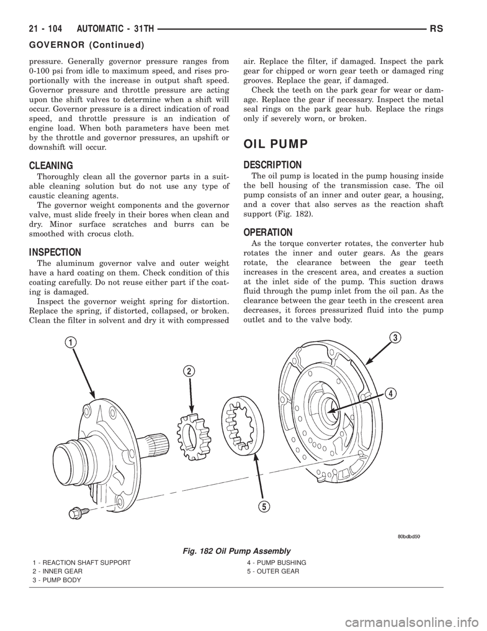
The oil pump is located in the pump housing inside
the bell housing of the transmission case. The oil
pump consists of an inner and outer gear, a housing,
and a cover that also serves as the reaction shaft
support (Fig. 182).
OPERATION
As the torque converter rotates, the converter hub
rotates the inner and outer gears. As the gears
rotate, the clearance between the gear teeth
increases in the crescent area, and creates a suction
at the inlet side of the pump. This suction draws
fluid through the pump inlet from the oil pan. As the
clearance between the gear teeth in the crescent area
decreases, it forces pressurized fluid into the pump
outlet and to the valve body.
Fig. 182 Oil Pump Assembly
1 - REACTION SHAFT SUPPORT
2 - INNER GEAR
3 - PUMP BODY4 - PUMP BUSHING
5 - OUTER GEAR
21 - 104 AUTOMATIC - 31THRS
GOVERNOR (Continued)
Page 3069 of 4284
STANDARD PROCEDURE - OIL PUMP VOLUME
CHECK
Measuring the oil pump output volume will deter-
mine if sufficient oil flow to the transmission oil
cooler exists, and whether or not an internal trans-
mission failure is present.
Verify that the transmission fluid is at the proper
level. Refer to the Fluid Level Check procedure in
this section. If necessary, fill the transmission to the
proper level with Moparž ATF +4, type 9602, Auto-
matic Transmission Fluid.
(1) Using hose cutters or a suitable blade, cut the
To coolerline off flush with the cooler inlet fitting
and place a collecting container under the open line.
CAUTION: With the fluid set at the proper level,
fluid collection should not exceed (1) quart or inter-
nal damage to the transmission may occur.
(2) Run the engineat curb idle speed, with the
shift selector in neutral.
(3) If one quart of transmission fluid is collected in
the container in 20 seconds or less, oil pump flow vol-
ume is within acceptable limits. If fluid flow is inter-
mittent, or it takes more than 20 seconds to collect
one quart of fluid, (Refer to 21 - TRANSMISSION/
TRANSAXLE/AUTOMATIC - 31TH - DIAGNOSIS
AND TESTING) for further diagnosis.
(4) Re-connect theTo coolerline to the transmis-
sion cooler inlet using a service splice kit. Refer to
instructions included with the kit.
(5) Refill the transmission to proper level. (Refer
to 21 - TRANSMISSION/TRANSAXLE/AUTOMATIC
- 31TH/FLUID - STANDARD PROCEDURE)
DISASSEMBLY
(1) Remove reaction shaft support-to-pump body
bolts.
(2) Remove reaction shaft support, and the inner
and outer pump gears (Fig. 183).
CLEANING
Clean pump and support components with solvent
and dry them with compressed air.
INSPECTION
(1) Check condition of the seal rings and thrust
washer on the reaction shaft support. The seal rings
do not need to be replaced unless cracked, broken, or
severely worn.
(2) Visually inspect the pump and support compo-
nents. Replace the pump assembly if the seal ring
grooves or machined surfaces are worn, scored, pit-
ted, or damaged. Replace the pump assembly if the
gears if pitted, worn chipped, or damaged.
(3) Inspect the pump bushing. Then check the
reaction shaft support bushing. Replace the pump
assembly if either bushing is heavily worn, scored or
damaged.
(4) Clearance between outer gear and reaction
shaft housing should be 0.010 to 0.063 mm (0.0004 to
0.0025 in.). Clearance between inner gear and reac-
tion shaft housing should be 0.010 to 0.063 mm
(0.0004 to 0.0025 in.). Both clearances can be mea-
sured at the same time by installing the gears in the
pump body and measure pump component clearances
as follows:
(5) Reinstall gears to pump body and measure
outer gear-to-pocket clearance with a feeler gauge
(Fig. 184).Outer gear-to-pocket clearance should
be within 0.045-0.141 mm (0.0018-0.0056 in.).
(6) Measure both inner and outer gear side clear-
ance with PlastigageŸ. If PlastigageŸ is not avail-
able, measure across the pump body with a straight
edge and feeler gauge.
(a) Position an appropriate piece of PlastigageŸ
across both gears.
(b) Align the plastigage to a flat area on the
reaction shaft housing.
(c) Install the reaction shaft support to the
pump housing and torque to 28 N´m (250 in. lbs.).
(d) Separate the reaction shaft housing from the
pump housing and measure the PlastigageŸ fol-
lowing the instructions supplied with it.Inner
and outer gear side clearance should be
within 0.020-0.046 mm (0.0008-0.0018 in.).
ASSEMBLY
(1) Install inner and outer gears to pump body
(Fig. 183). Lubricate gears with Moparž ATF+4
(Automatic Transmission Fluid-Type 9602).
(2) Install reaction shaft support to pump body
and align holes.
(3) Install and torque reaction shaft support-to-
pump body bolts to 28 N´m (250 in. lbs.).
RSAUTOMATIC - 31TH21 - 105
OIL PUMP (Continued)
Page 3075 of 4284
CLEANING
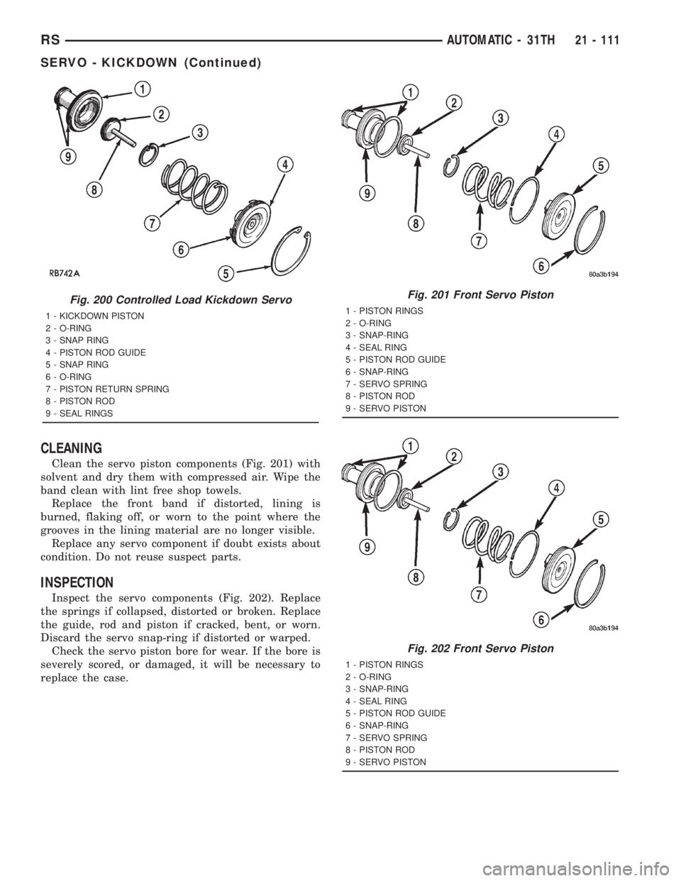
Clean the servo piston components (Fig. 201) with
solvent and dry them with compressed air. Wipe the
band clean with lint free shop towels.
Replace the front band if distorted, lining is
burned, flaking off, or worn to the point where the
grooves in the lining material are no longer visible.
Replace any servo component if doubt exists about
condition. Do not reuse suspect parts.
INSPECTION
Inspect the servo components (Fig. 202). Replace
the springs if collapsed, distorted or broken. Replace
the guide, rod and piston if cracked, bent, or worn.
Discard the servo snap-ring if distorted or warped.
Check the servo piston bore for wear. If the bore is
severely scored, or damaged, it will be necessary to
replace the case.
Fig. 200 Controlled Load Kickdown Servo
1 - KICKDOWN PISTON
2 - O-RING
3 - SNAP RING
4 - PISTON ROD GUIDE
5 - SNAP RING
6 - O-RING
7 - PISTON RETURN SPRING
8 - PISTON ROD
9 - SEAL RINGS
Fig. 201 Front Servo Piston
1 - PISTON RINGS
2 - O-RING
3 - SNAP-RING
4 - SEAL RING
5 - PISTON ROD GUIDE
6 - SNAP-RING
7 - SERVO SPRING
8 - PISTON ROD
9 - SERVO PISTON
Fig. 202 Front Servo Piston
1 - PISTON RINGS
2 - O-RING
3 - SNAP-RING
4 - SEAL RING
5 - PISTON ROD GUIDE
6 - SNAP-RING
7 - SERVO SPRING
8 - PISTON ROD
9 - SERVO PISTON
RSAUTOMATIC - 31TH21 - 111
SERVO - KICKDOWN (Continued)