2001 CHRYSLER VOYAGER torque
[x] Cancel search: torquePage 2844 of 4284
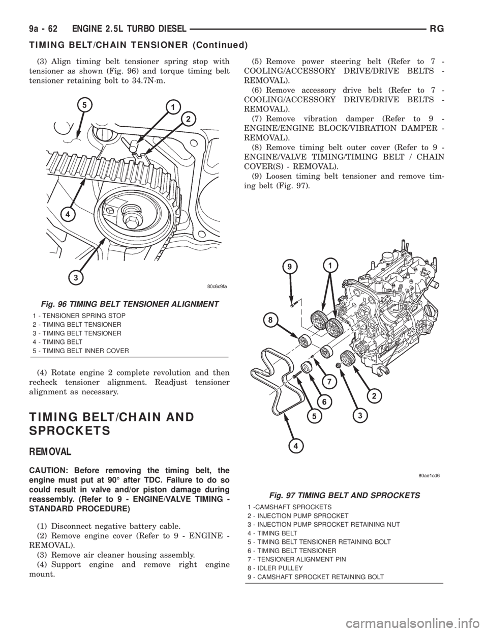
(3) Align timing belt tensioner spring stop with
tensioner as shown (Fig. 96) and torque timing belt
tensioner retaining bolt to 34.7N´m.
(4) Rotate engine 2 complete revolution and then
recheck tensioner alignment. Readjust tensioner
alignment as necessary.
TIMING BELT/CHAIN AND
SPROCKETS
REMOVAL
CAUTION: Before removing the timing belt, the
engine must put at 90É after TDC. Failure to do so
could result in valve and/or piston damage during
reassembly. (Refer to 9 - ENGINE/VALVE TIMING -
STANDARD PROCEDURE)
(1) Disconnect negative battery cable.
(2) Remove engine cover (Refer to 9 - ENGINE -
REMOVAL).
(3) Remove air cleaner housing assembly.
(4) Support engine and remove right engine
mount.(5) Remove power steering belt (Refer to 7 -
COOLING/ACCESSORY DRIVE/DRIVE BELTS -
REMOVAL).
(6) Remove accessory drive belt (Refer to 7 -
COOLING/ACCESSORY DRIVE/DRIVE BELTS -
REMOVAL).
(7) Remove vibration damper (Refer to 9 -
ENGINE/ENGINE BLOCK/VIBRATION DAMPER -
REMOVAL).
(8) Remove timing belt outer cover (Refer to 9 -
ENGINE/VALVE TIMING/TIMING BELT / CHAIN
COVER(S) - REMOVAL).
(9) Loosen timing belt tensioner and remove tim-
ing belt (Fig. 97).
Fig. 96 TIMING BELT TENSIONER ALIGNMENT
1 - TENSIONER SPRING STOP
2 - TIMING BELT TENSIONER
3 - TIMING BELT TENSIONER
4 - TIMING BELT
5 - TIMING BELT INNER COVER
Fig. 97 TIMING BELT AND SPROCKETS
1 -CAMSHAFT SPROCKETS
2 - INJECTION PUMP SPROCKET
3 - INJECTION PUMP SPROCKET RETAINING NUT
4 - TIMING BELT
5 - TIMING BELT TENSIONER RETAINING BOLT
6 - TIMING BELT TENSIONER
7 - TENSIONER ALIGNMENT PIN
8 - IDLER PULLEY
9 - CAMSHAFT SPROCKET RETAINING BOLT
9a - 62 ENGINE 2.5L TURBO DIESELRG
TIMING BELT/CHAIN TENSIONER (Continued)
Page 2849 of 4284
NOTE: For applications with dual catalytic convert-
ers, repeat test on opposite converter using the
previous steps.
(7) If pressure exceeds maximum limits, inspect
exhaust system for restricted component. For further
catalytic converter inspection procedures, (Refer to 11
- EXHAUST SYSTEM/CATALYTIC CONVERTER -
INSPECTION). Replace component(s) as necessary.
EXHAUST BACK PRESSURE LIMITS
Exhaust Back Pressure Limit (Max)
Vehicle in Park/Neutral
(no load) RPM3.45 Kpa (0.5 psi)
INSPECTION
Inspect the exhaust pipes, catalytic converters,
muffler, and resonators for cracked joints, broken
welds and corrosion damage that would result in a
leaking exhaust system. Inspect the clamps, support
brackets, and insulators for cracks and corrosion
damage.
NOTE: Slip joint band clamps are spot welded to
exhaust system. If a band clamp must be replaced,
the spot weld must be ground off.
ADJUSTMENTS
A misaligned exhaust system is usually indicated
by a vibration, rattling noise, or binding of exhaust
system components. These noises are sometimes hard
to distinguish from other chassis noises. Inspect
exhaust system for broken, damaged or loose compo-
nents such as; clamps, heat shields, isolators, and
hanger brackets. Replace or tighten as necessary. It
is important that exhaust system clearances and
alignment be maintained.
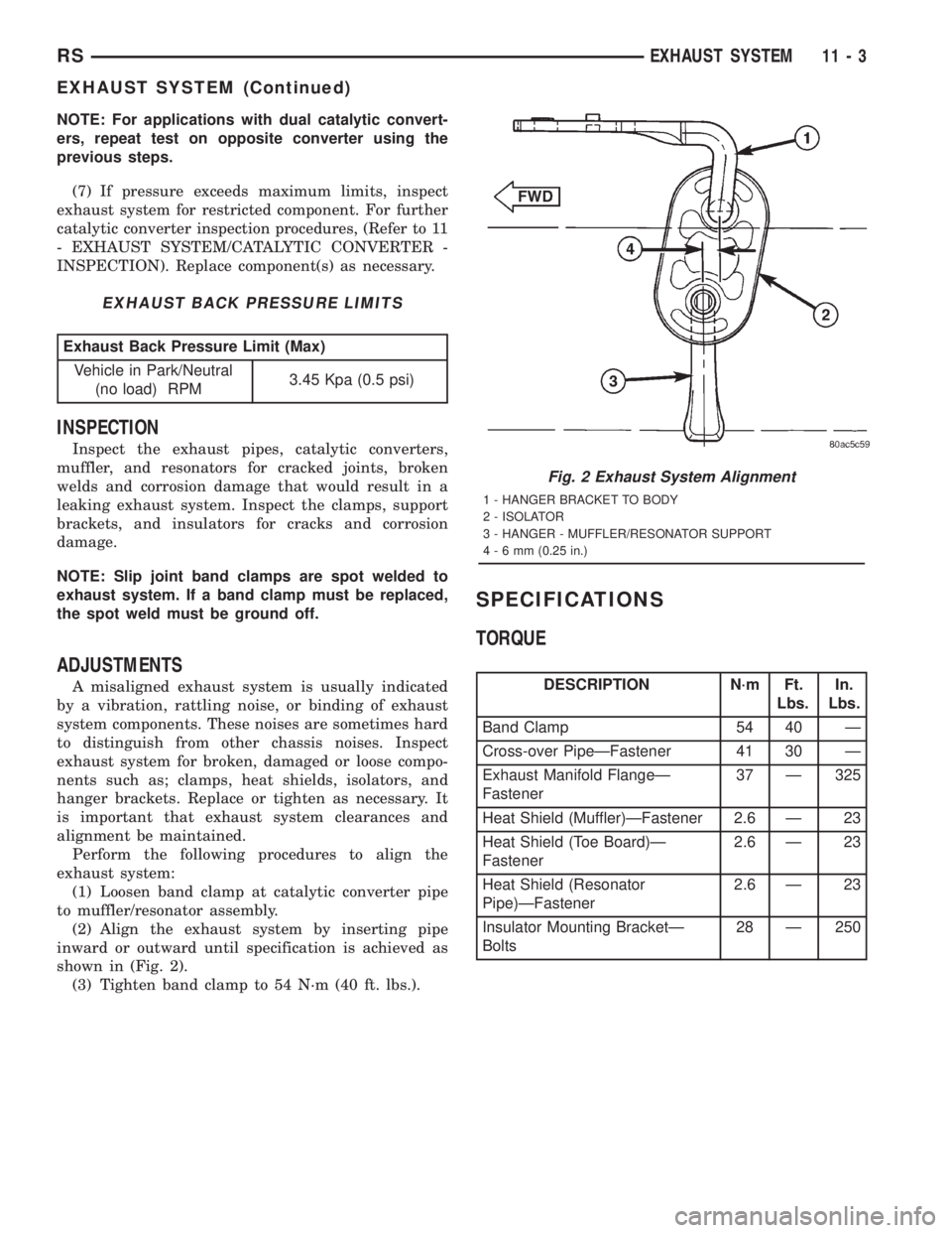
Perform the following procedures to align the
exhaust system:
(1) Loosen band clamp at catalytic converter pipe
to muffler/resonator assembly.
(2) Align the exhaust system by inserting pipe
inward or outward until specification is achieved as
shown in (Fig. 2).
(3) Tighten band clamp to 54 N´m (40 ft. lbs.).
SPECIFICATIONS
TORQUE
DESCRIPTION N´m Ft.
Lbs.In.
Lbs.
Band Clamp 54 40 Ð
Cross-over PipeÐFastener 41 30 Ð
Exhaust Manifold FlangeÐ
Fastener37 Ð 325
Heat Shield (Muffler)ÐFastener 2.6 Ð 23
Heat Shield (Toe Board)Ð
Fastener2.6 Ð 23
Heat Shield (Resonator
Pipe)ÐFastener2.6 Ð 23
Insulator Mounting BracketÐ
Bolts28 Ð 250
Fig. 2 Exhaust System Alignment
1 - HANGER BRACKET TO BODY
2 - ISOLATOR
3 - HANGER - MUFFLER/RESONATOR SUPPORT
4-6mm(0.25 in.)
RSEXHAUST SYSTEM11-3
EXHAUST SYSTEM (Continued)
Page 2854 of 4284
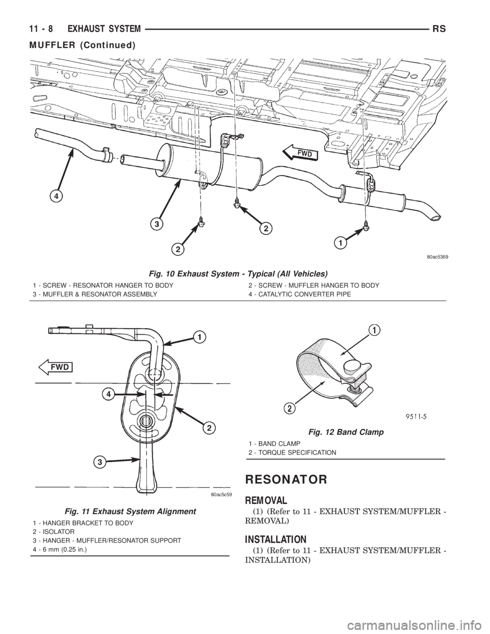
RESONATOR
REMOVAL
(1) (Refer to 11 - EXHAUST SYSTEM/MUFFLER -
REMOVAL)
INSTALLATION
(1) (Refer to 11 - EXHAUST SYSTEM/MUFFLER -
INSTALLATION)
Fig. 10 Exhaust System - Typical (All Vehicles)
1 - SCREW - RESONATOR HANGER TO BODY
3 - MUFFLER & RESONATOR ASSEMBLY2 - SCREW - MUFFLER HANGER TO BODY
4 - CATALYTIC CONVERTER PIPE
Fig. 11 Exhaust System Alignment
1 - HANGER BRACKET TO BODY
2 - ISOLATOR
3 - HANGER - MUFFLER/RESONATOR SUPPORT
4-6mm(0.25 in.)
Fig. 12 Band Clamp
1 - BAND CLAMP
2 - TORQUE SPECIFICATION
11 - 8 EXHAUST SYSTEMRS
MUFFLER (Continued)
Page 2855 of 4284
EXHAUST SYSTEM AND TURBOCHARGER
TABLE OF CONTENTS
page page
EXHAUST SYSTEM AND TURBOCHARGER
DESCRIPTION............................1
SPECIFICATIONS.........................1
TURBOCHARGER SYSTEM
DESCRIPTION............................2
OPERATION.............................2
TURBOCHARGER
REMOVAL...............................4CLEANING...............................5
INSTALLATION............................5
HEAT SHIELDS
REMOVAL...............................5
INSTALLATION............................6
EXHAUST SYSTEM AND
TURBOCHARGER
DESCRIPTION
The basic exhaust system consists of an engine
exhaust manifold, turbocharger, exhaust down pipe,
exhaust pipe, exhaust heat shield(s), muffler and
exhaust tailpipe
The exhaust system uses a single muffler.
The exhaust system must be properly aligned to
prevent stress, leakage and body contact. If the sys-
tem contacts any body panel, it will transfer objec-
tionable noises originating from the engine to the
body.
When inspecting an exhaust system, critically
inspect for cracked or loose joints, stripped screw orbolt threads, corrosion damage and worn, cracked or
broken hangers. Replace all components that are
badly corroded or damaged. DO NOT attempt to
repair.
When replacement is required, use original equip-
ment parts (or equivalent). This will assure proper
alignment and provide acceptable exhaust noise lev-
els.
CAUTION: Avoid application of rust prevention com-
pounds or undercoating materials to exhaust sys-
tem floor pan exhaust heat shields. Light overspray
near the edges is permitted. Application of coating
will result in excessive floor pan temperatures and
objectionable fumes.
SPECIFICATIONS
SPECIFICATIONS - TORQUE
2.5L DIESEL - TORQUE SPECIFICATIONS
DESCRIPTION N´m Ft. Lbs. In. Lbs.
Turbocharger Oil Feed
Line Fitting24.5 18 215
Exhaust Manifold Nuts 32.4 24 Ð
Exhaust Manifold Heat
shield Bolts27.5 21 Ð
Turbocharger Downpipe
Nuts32.4 24 Ð
Turbocharger Bracket
Bolts47.1 35 Ð
Turbocharger to Exhaust
Manifold Nuts32.4 24 Ð
RGEXHAUST SYSTEM AND TURBOCHARGER11a-1
Page 2859 of 4284

(8) With exhaust manifold and turbocharger
assembly on work bench, remove turbocharger to
exhaust manifold retaining bolts. Separate exhaust
manifold and turbocharger.
CLEANING
All old gaskets should be inspected for any tears or
signs of prior leakage. If any gaskets show such indi-
cations, they should be replaced with new gaskets.
All gasket mating surfaces must be cleaned of old
gasket material to produce a smooth and dirt free
sealing surface for the new gasket.
INSTALLATION
(1) Connect exhaust manifold and turbocharger.
Torque nuts to 32.4N´m.
(2) Position new exhaust manifol gasket on
exhaust manifol studs (Fig. 6).
(3) Install exhaust manifold and turbocharger on
engine (Fig. 6). Torque nuts to 32.4N´m.
(4) Connect turbocharger oil supply and return
lines at turbocharger (Fig. 6). Torque oil supply line
to 24.5N´m.
(5) Install exhaust manifold shield (Fig. 6). Torque
bolts to 27.5N´m.
(6) Install engine lift hook (Fig. 6). Torque bolts to
32.4N´m.
(7) Install thermostat to upper radiator hose tube
and turbocharger outlet tube (Fig. 5).
(8) Install engine in vehicle (Refer to 9 - ENGINE
- INSTALLATION).
HEAT SHIELDS
REMOVAL
(1) Remove front wiper unit (Refer to 8 - ELEC-
TRICAL/WIPERS/WASHERS/WIPER MODULE -
REMOVAL).
(2) Remove engine cover (Refer to 9 - ENGINE -
REMOVAL).
(3) Partially drain cooling system (Refer to 7 -
COOLING/ENGINE/COOLANT - STANDARD PRO-
CEDURE).
(4) Remove thermostat housing to upper radiator
hose tube (Fig. 7).
(5) Remove exhaust manifold heat shield retaining
bolts and remove shield (Fig. 8).
Fig. 7 TURBOCHARGER AND COOLANT PIPES
1 - TURBOCHARGER OUTLET PIPE RETAINING BOLT
2 - TURBOCHARGER OUTLET PIPE
3 - ADAPTER HOSE
4 - HEAT SHIELD
5 - HOSE CLAMPS
6 - TURBOCHARGER INLET PIPE RETAINING BOLT
7 - TURBOCHARGER INLET PIPE
8 - ADAPTER HOSE
9 - HOSE CLAMPS
10 - CLAMP
11 - EGR VALVE TO INTAKE AIR INLET PIPE
12 - CLAMP
13 - THERMOSTAT HOUSING TO UPPER RADIATOR HOSE
PIPE
RGEXHAUST SYSTEM AND TURBOCHARGER11a-5
TURBOCHARGER (Continued)
Page 2860 of 4284
INSTALLATION
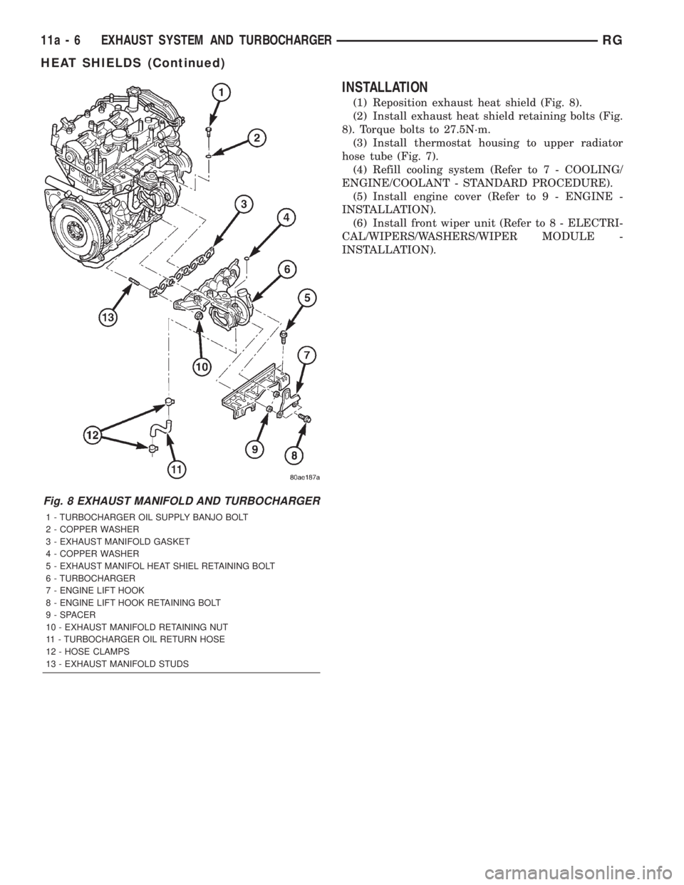
(1) Reposition exhaust heat shield (Fig. 8).
(2) Install exhaust heat shield retaining bolts (Fig.
8). Torque bolts to 27.5N´m.
(3) Install thermostat housing to upper radiator
hose tube (Fig. 7).
(4) Refill cooling system (Refer to 7 - COOLING/
ENGINE/COOLANT - STANDARD PROCEDURE).
(5) Install engine cover (Refer to 9 - ENGINE -
INSTALLATION).
(6) Install front wiper unit (Refer to 8 - ELECTRI-
CAL/WIPERS/WASHERS/WIPER MODULE -
INSTALLATION).
Fig. 8 EXHAUST MANIFOLD AND TURBOCHARGER
1 - TURBOCHARGER OIL SUPPLY BANJO BOLT
2 - COPPER WASHER
3 - EXHAUST MANIFOLD GASKET
4 - COPPER WASHER
5 - EXHAUST MANIFOL HEAT SHIEL RETAINING BOLT
6 - TURBOCHARGER
7 - ENGINE LIFT HOOK
8 - ENGINE LIFT HOOK RETAINING BOLT
9 - SPACER
10 - EXHAUST MANIFOLD RETAINING NUT
11 - TURBOCHARGER OIL RETURN HOSE
12 - HOSE CLAMPS
13 - EXHAUST MANIFOLD STUDS
11a - 6 EXHAUST SYSTEM AND TURBOCHARGERRG
HEAT SHIELDS (Continued)
Page 2861 of 4284
FRAMES & BUMPERS
TABLE OF CONTENTS
page page
BUMPERS
DESCRIPTION............................1
SPECIFICATIONS.........................1
FRONT FASCIA
REMOVAL...............................2
INSTALLATION............................2
FRONT BUMPER REINFORCEMENT
REMOVAL...............................2
INSTALLATION............................3
REAR FASCIA
REMOVAL...............................3
INSTALLATION............................3
REAR BUMPER REINFORCEMENT
REMOVAL...............................3INSTALLATION............................4
REAR FASCIA - SCUFF PAD
REMOVAL...............................4
INSTALLATION............................4
FRAME
DESCRIPTION............................4
SPECIFICATIONS.........................4
FRONT CRADLE CROSSMEMBER
DESCRIPTION............................9
REMOVAL..............................10
INSTALLATION...........................11
FRONT CROSSMEMBER MOUNT BUSHINGS
REMOVAL..............................11
INSTALLATION...........................11
BUMPERS
DESCRIPTION
BUMPERS
The bumpers are made up of bumper reinforce-
ment and fascia with air deflector (front bumper) and
mounting brackets.The bumper reinforcement is fastened to the unit-
ized body frame rails on the front and to the rail
extensions on the rear. The bumper fascia is fastened
to the body side sheet metal.
SPECIFICATIONS
TORQUE SPECIFICATIONS
DESCRIPTION N´m Ft. Lbs. In. Lbs.
Front bumper reinforcement attaching nut 54 40 Ð
Rear bumper reinforcement attaching nut 27 20 Ð
RSFRAMES & BUMPERS13-1
Page 2863 of 4284
INSTALLATION
NOTE: Check position of the arrows molded into
the foam for correct orientation.
(1) Position front bumper reinforcement on vehicle.
(2) Install the four nuts to hold reinforcement to
frame rails. Tighten nuts to 54 N´m (40 ft. lbs.)
torque.
(3) Install front fascia. (Refer to 13 - FRAMES &
BUMPERS/BUMPERS/FRONT FASCIA - INSTAL-
LATION)
REAR FASCIA
REMOVAL
(1) Open liftgate.
(2) Remove the two screws attaching the upper
fascia to the body.
(3) Hoist and support vehicle on safety stands.
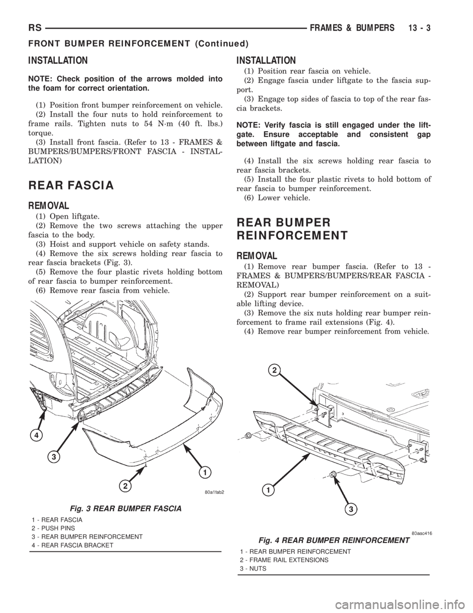
(4) Remove the six screws holding rear fascia to
rear fascia brackets (Fig. 3).
(5) Remove the four plastic rivets holding bottom
of rear fascia to bumper reinforcement.
(6) Remove rear fascia from vehicle.
INSTALLATION
(1) Position rear fascia on vehicle.
(2) Engage fascia under liftgate to the fascia sup-
port.
(3) Engage top sides of fascia to top of the rear fas-
cia brackets.
NOTE: Verify fascia is still engaged under the lift-
gate. Ensure acceptable and consistent gap
between liftgate and fascia.
(4) Install the six screws holding rear fascia to
rear fascia brackets.
(5) Install the four plastic rivets to hold bottom of
rear fascia to bumper reinforcement.
(6) Lower vehicle.
REAR BUMPER
REINFORCEMENT
REMOVAL
(1) Remove rear bumper fascia. (Refer to 13 -
FRAMES & BUMPERS/BUMPERS/REAR FASCIA -
REMOVAL)
(2) Support rear bumper reinforcement on a suit-
able lifting device.
(3) Remove the six nuts holding rear bumper rein-
forcement to frame rail extensions (Fig. 4).
(4)
Remove rear bumper reinforcement from vehicle.
Fig. 3 REAR BUMPER FASCIA
1 - REAR FASCIA
2 - PUSH PINS
3 - REAR BUMPER REINFORCEMENT
4 - REAR FASCIA BRACKET
Fig. 4 REAR BUMPER REINFORCEMENT
1 - REAR BUMPER REINFORCEMENT
2 - FRAME RAIL EXTENSIONS
3 - NUTS
RSFRAMES & BUMPERS13-3
FRONT BUMPER REINFORCEMENT (Continued)