2001 CHRYSLER VOYAGER torque
[x] Cancel search: torquePage 2895 of 4284
ACCELERATOR PEDAL
REMOVAL
(1) Hold the throttle body throttle lever in the
wide open position. Remove the throttle cable from
the throttle body cam.
(2) From inside the vehicle, hold up the pedal and
remove the cable retainer and throttle cable from the
upper end of the pedal shaft.
(3) Remove nuts from accelerator pedal attaching
studs. Remove assembly from vehicle.
INSTALLATION
(1) Position accelerator pedal assembly on dash
panel. Install retaining nuts. Tighten retaining nuts
to 12 N´m (105 in. lbs.) torque.
(2) From inside the vehicle, hold up the pedal and
install the throttle cable and cable retainer in the
upper end of the pedal shaft.
(3) From the engine compartment, hold the throt-
tle body lever in the wide open position and install
the throttle cable.
CRANKSHAFT POSITION
SENSOR
DESCRIPTION
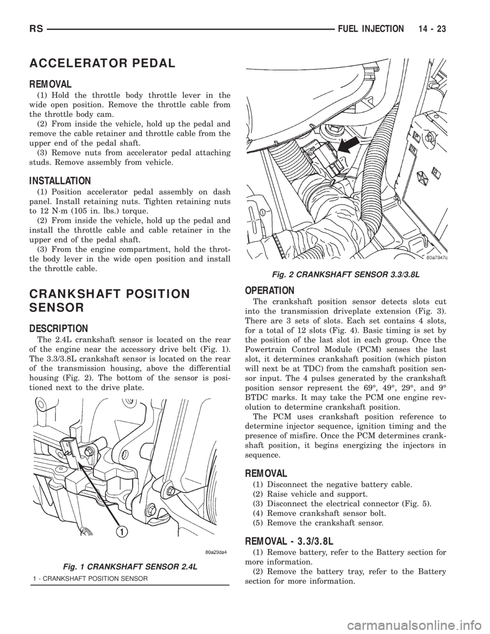
The 2.4L crankshaft sensor is located on the rear
of the engine near the accessory drive belt (Fig. 1).
The 3.3/3.8L crankshaft sensor is located on the rear
of the transmission housing, above the differential
housing (Fig. 2). The bottom of the sensor is posi-
tioned next to the drive plate.
OPERATION
The crankshaft position sensor detects slots cut
into the transmission driveplate extension (Fig. 3).
There are 3 sets of slots. Each set contains 4 slots,
for a total of 12 slots (Fig. 4). Basic timing is set by
the position of the last slot in each group. Once the
Powertrain Control Module (PCM) senses the last
slot, it determines crankshaft position (which piston
will next be at TDC) from the camshaft position sen-
sor input. The 4 pulses generated by the crankshaft
position sensor represent the 69É, 49É, 29É, and 9É
BTDC marks. It may take the PCM one engine rev-
olution to determine crankshaft position.
The PCM uses crankshaft position reference to
determine injector sequence, ignition timing and the
presence of misfire. Once the PCM determines crank-
shaft position, it begins energizing the injectors in
sequence.
REMOVAL
(1) Disconnect the negative battery cable.
(2) Raise vehicle and support.
(3) Disconnect the electrical connector (Fig. 5).
(4) Remove crankshaft sensor bolt.
(5) Remove the crankshaft sensor.
REMOVAL - 3.3/3.8L
(1) Remove battery, refer to the Battery section for
more information.
(2) Remove the battery tray, refer to the Battery
section for more information.
Fig. 1 CRANKSHAFT SENSOR 2.4L
1 - CRANKSHAFT POSITION SENSOR
Fig. 2 CRANKSHAFT SENSOR 3.3/3.8L
RSFUEL INJECTION14-23
Page 2896 of 4284

(3) Disconnect the speed control vacuum harness
from servo.
(4) Remove the speed control servo and bracket
and reposition. Disconnect the electrical connector.
(5) Disconnect the electrical connector from crank-
shaft sensor.
(6) Remove the mounting bolt.
(7) Remove sensor.
INSTALLATION - 2.4L
(1) Install the crankshaft sensor.
(2) Install crankshaft sensor bolt and tighten.
(3) Connect the electrical connector (Fig. 5).
(4) Lower vehicle.
(5) Connect the negative battery cable.
INSTALLATION - 3.3/3.8L
(1) Install the crankshaft sensor.
(2) Install the mounting bolt and tighten.
(3) Connect the electrical connector to crankshaft
sensor. Make sure locking tab is in position.
(4) Connect the electrical connector to the speed
control servo.
(5) Install the speed control servo and bracket.
(6) Connect the speed control vacuum harness to
servo.
(7) Install the battery tray, refer to the Battery
section for more information.
(8) Install battery, refer to the Battery section for
more information.
ENGINE SPEED SENSOR
DESCRIPTION
The PCM receives a signal from the TCM and the
transaxle output speed sensor over the bus communi-
cation line.
OPERATION
The Transmission Control Module (TCM) supplies
the road speed and distance traveled inputs to the
PCM. From these inputs and the throttle position
sensor input, the PCM determines when a decelera-
tion condition occurs.
Fig. 3 Crankshaft Position Sensor
1 - CRANKSHAFT POSITION SENSOR
Fig. 4 Timing Slots
1 - TORQUE CONVERTER DRIVE PLATE
2 - SLOTS
Fig. 5 CRANKSHAFT SENSOR 2.4L
1 - CRANKSHAFT POSITION SENSOR
14 - 24 FUEL INJECTIONRS
CRANKSHAFT POSITION SENSOR (Continued)
Page 2900 of 4284
²TPS
²MAP Sensor
REMOVAL
When servicing throttle body components, always
reassemble components with new O-rings and seals
where applicable. Never use lubricants on O-rings or
seals, damage may result. If assembly of component
is difficult, use water to aid assembly. Use care when
removing hoses to prevent damage to hose or hose
nipple.
(1) Disconnect negative cable from battery.
(2) Remove electrical connector from idle air con-
trol motor.
(3) Remove idle air control motor mounting screws.
(4) Remove motor from throttle body. Ensure the
O-rings is removed with the motor.
INSTALLATION
When servicing throttle body components, always
reassemble components with new O-rings and seals
where applicable. Never use lubricants on O-rings or
seals, damage may result. If assembly of component
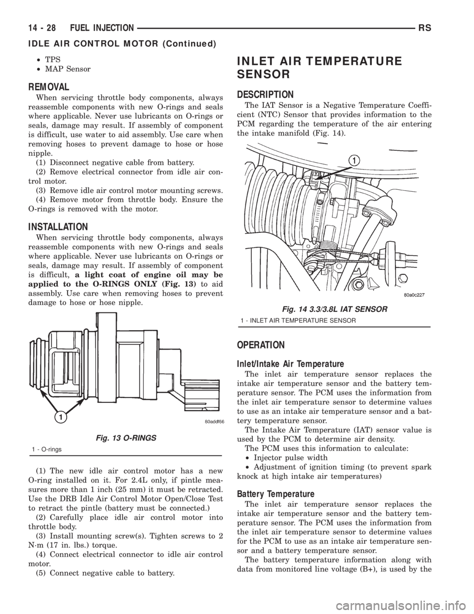
is difficult,a light coat of engine oil may be
applied to the O-RINGS ONLY (Fig. 13)to aid
assembly. Use care when removing hoses to prevent
damage to hose or hose nipple.
(1) The new idle air control motor has a new
O-ring installed on it. For 2.4L only, if pintle mea-
sures more than 1 inch (25 mm) it must be retracted.
Use the DRB Idle Air Control Motor Open/Close Test
to retract the pintle (battery must be connected.)
(2) Carefully place idle air control motor into
throttle body.
(3) Install mounting screw(s). Tighten screws to 2
N´m (17 in. lbs.) torque.
(4) Connect electrical connector to idle air control
motor.
(5) Connect negative cable to battery.
INLET AIR TEMPERATURE
SENSOR
DESCRIPTION
The IAT Sensor is a Negative Temperature Coeffi-
cient (NTC) Sensor that provides information to the
PCM regarding the temperature of the air entering
the intake manifold (Fig. 14).
OPERATION
Inlet/Intake Air Temperature
The inlet air temperature sensor replaces the
intake air temperature sensor and the battery tem-
perature sensor. The PCM uses the information from
the inlet air temperature sensor to determine values
to use as an intake air temperature sensor and a bat-
tery temperature sensor.
The Intake Air Temperature (IAT) sensor value is
used by the PCM to determine air density.
The PCM uses this information to calculate:
²Injector pulse width
²Adjustment of ignition timing (to prevent spark
knock at high intake air temperatures)
Battery Temperature
The inlet air temperature sensor replaces the
intake air temperature sensor and the battery tem-
perature sensor. The PCM uses the information from
the inlet air temperature sensor to determine values
for the PCM to use as an intake air temperature sen-
sor and a battery temperature sensor.
The battery temperature information along with
data from monitored line voltage (B+), is used by the
Fig. 13 O-RINGS
1 - O-rings
Fig. 14 3.3/3.8L IAT SENSOR
1 - INLET AIR TEMPERATURE SENSOR
14 - 28 FUEL INJECTIONRS
IDLE AIR CONTROL MOTOR (Continued)
Page 2906 of 4284
OPERATION
Filtered air from the air cleaner enters the intake
manifold through the throttle body. The throttle body
contains an air control passage controlled by an Idle
Air Control (IAC) motor. The air control passage is
used to supply air for idle conditions. A throttle valve
(plate) is used to supply air for above idle conditions.
Certain sensors are attached to the throttle body.
The accelerator pedal cable, speed control cable and
transmission control cable (when equipped) are con-
nected to the throttle body linkage arm.
A (factory adjusted) set screw is used to mechani-
cally limit the position of the throttle body throttle
plate.Never attempt to adjust the engine idle
speed using this screw.All idle speed functions are
controlled by the PCM.
REMOVAL
(1) Disconnect negative cable from battery cable.
(2) Remove air inlet to throttle body hose clamp.
(3) Remove throttle and the speed control (if
equipped) cables from lever and bracket.
(4) Disconnect electrical connectors from the idle
air control motor and throttle position sensor (TPS)
(Fig. 23) or (Fig. 24).
(5) Remove throttle body to intake manifold
attaching bolts.
(6) Remove throttle body and gasket.
INSTALLATION
(1) Install a new gasket.
(2) Install throttle body.
(3) Tighten throttle body mounting bolts. The 2.4L
to 28.2 N´m (250650 in. lbs.) torque, The 3.3/3.8L to
11.6 N´m (105620 in. lbs.) torque.
(4) Connect electrical connectors to the idle air
control motor and throttle position sensor (TPS) (Fig.
23) or (Fig. 24).
(5) Install air inlet to throttle body hose clamp and
tighten.
(6) Connect negative cable to battery cable.
THROTTLE CONTROL CABLE
REMOVAL
(1) Working from the engine compartment, hold
the throttle body throttle lever in the wide open posi-
tion.
(2) Remove the throttle cable from the throttle
body cam.
(3) From inside the vehicle, hold up the pedal and
remove the cable retainer and throttle cable from the
upper end of the pedal shaft.
(4) Remove retainer clip from throttle cable and
grommet at dash panel.(5) From the engine compartment, pull the throttle
cable out of the dash panel grommet. The grommet
should remain in the dash panel.
(6) Remove the throttle cable from throttle bracket
by carefully compressing both retaining ears simulta-
neously. Then gently pull the throttle cable from
throttle bracket.
INSTALLATION
(1) From the engine compartment, push the hous-
ing end fitting into the dash panel grommet.
(2) Install the cable housing (throttle body end)
into the cable mounting bracket on the engine.
(3) From inside the vehicle, hold up the pedal and
install throttle cable and cable retainer in the upper
end of the pedal shaft.
(4) At the dash panel, install the cable retainer
clip between the end of the throttle cable fitting and
grommet
(5) From the engine compartment, rotate the
throttle lever wide open and install the throttle
cable.
THROTTLE POSITION SENSOR
DESCRIPTION
The throttle position sensor mounts to the side of
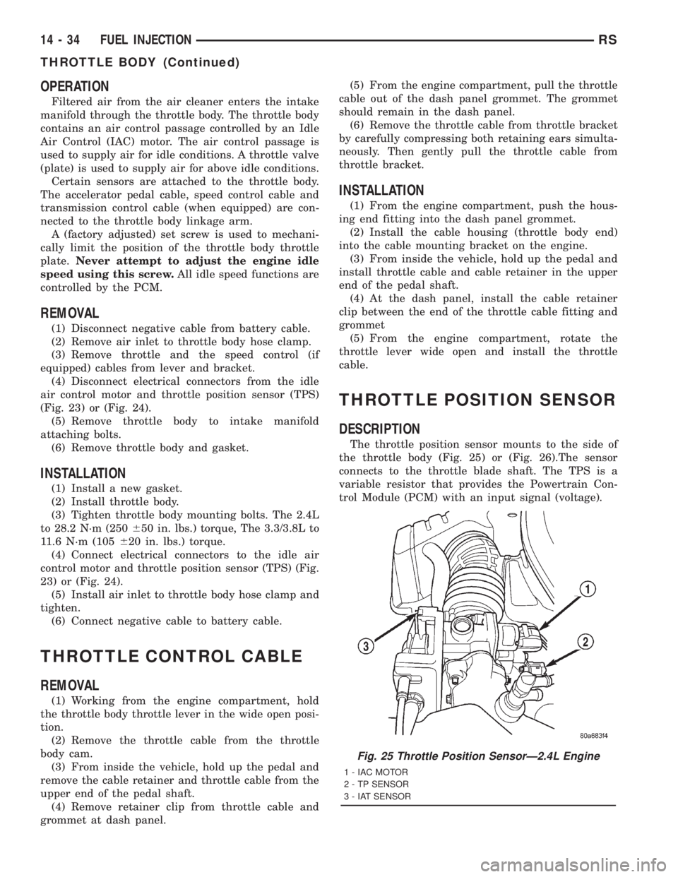
the throttle body (Fig. 25) or (Fig. 26).The sensor
connects to the throttle blade shaft. The TPS is a
variable resistor that provides the Powertrain Con-
trol Module (PCM) with an input signal (voltage).
Fig. 25 Throttle Position SensorÐ2.4L Engine
1 - IAC MOTOR
2 - TP SENSOR
3 - IAT SENSOR
14 - 34 FUEL INJECTIONRS
THROTTLE BODY (Continued)
Page 2910 of 4284
Replace damaged, restricted or leaking high-pres-
sure fuel lines with correct replacement line.
CAUTION: High pressure lines cannot contact each
other or other components. Do not attempt to weld
high-pressure fuel lines or to repair lines that are
damaged. If line is kinked or bent, it must be
replaced. Use only recommended lines when
replacement of high-pressure fuel line is necessary.
STANDARD PROCEDURE - WATER DRAINING
AT FUEL FILTER
Refer to Fuel Filter/Water Separator removal/in-
stallation for procedures.
STANDARD PROCEDURE - CLEANING FUEL
SYSTEM PARTS
CAUTION: Cleanliness cannot be overemphasized
when handling or replacing diesel fuel system com-
ponents. This especially includes the fuel injectors,
high-pressure fuel lines, fuel rail, and fuel injection
pump. Very tight tolerances are used with these
parts. Dirt contamination could cause rapid part
wear and possible plugging of fuel injector nozzle
tip holes. This in turn could lead to possible engine
misfire. Always wash/clean any fuel system compo-
nent thoroughly before disassembly and then air
dry. Cap or cover any open part after disassembly.
Before assembly, examine each part for dirt, grease
or other contaminants and clean if necessary. When
installing new parts, lubricate them with clean
engine oil or clean diesel fuel only.
SPECIFICATIONS
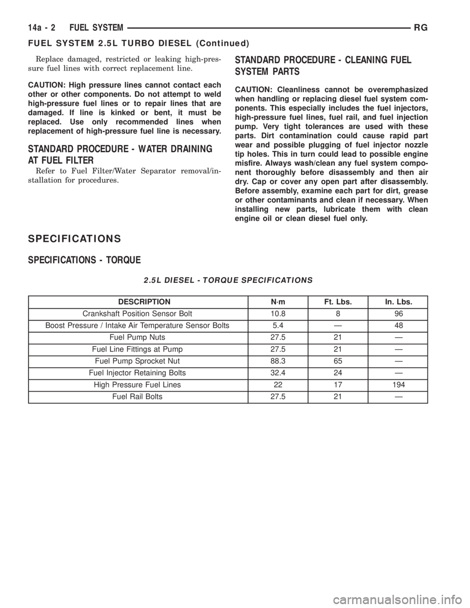
SPECIFICATIONS - TORQUE
2.5L DIESEL - TORQUE SPECIFICATIONS
DESCRIPTION N´m Ft. Lbs. In. Lbs.
Crankshaft Position Sensor Bolt 10.8 8 96
Boost Pressure / Intake Air Temperature Sensor Bolts 5.4 Ð 48
Fuel Pump Nuts 27.5 21 Ð
Fuel Line Fittings at Pump 27.5 21 Ð
Fuel Pump Sprocket Nut 88.3 65 Ð
Fuel Injector Retaining Bolts 32.4 24 Ð
High Pressure Fuel Lines 22 17 194
Fuel Rail Bolts 27.5 21 Ð
14a - 2 FUEL SYSTEMRG
FUEL SYSTEM 2.5L TURBO DIESEL (Continued)
Page 2912 of 4284
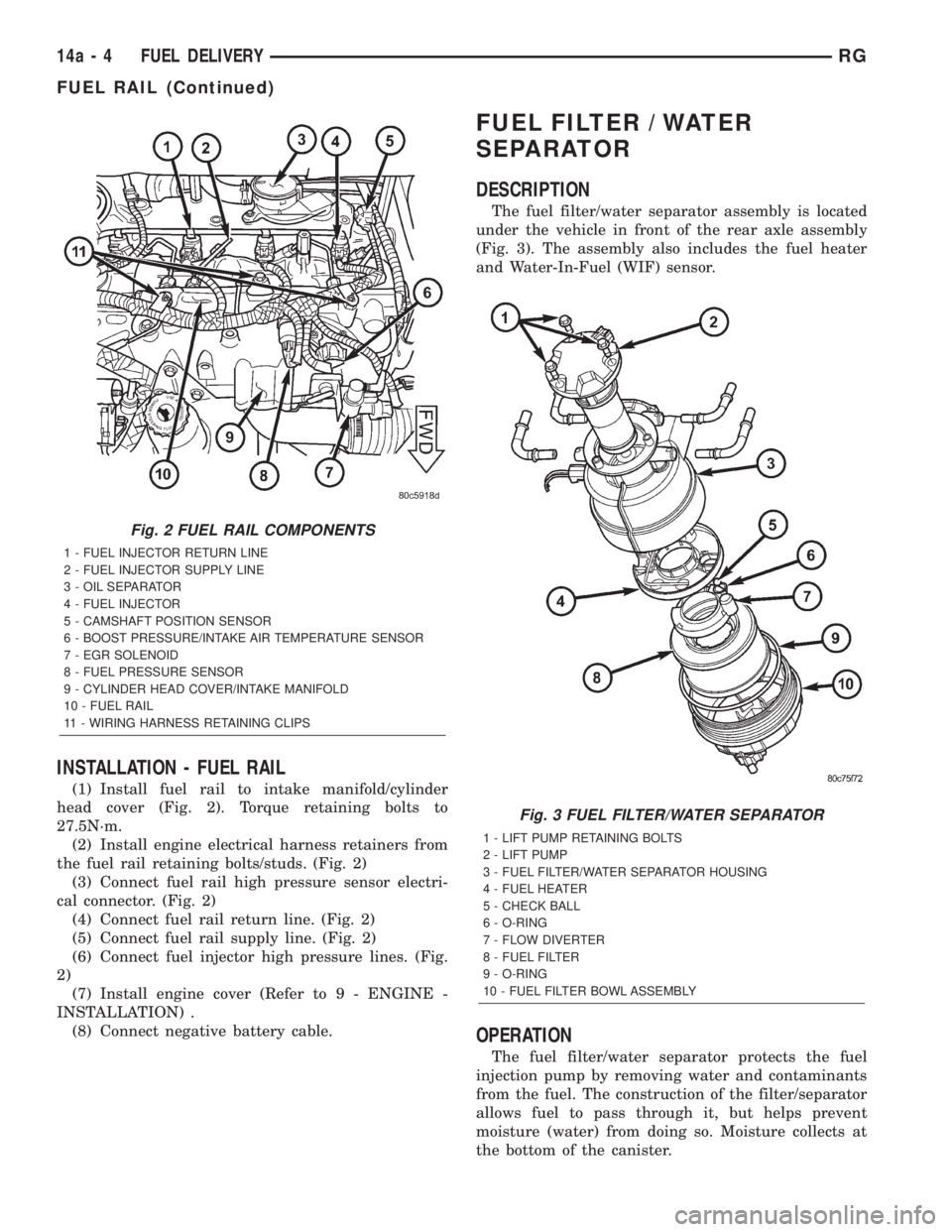
INSTALLATION - FUEL RAIL
(1) Install fuel rail to intake manifold/cylinder
head cover (Fig. 2). Torque retaining bolts to
27.5N´m.
(2) Install engine electrical harness retainers from
the fuel rail retaining bolts/studs. (Fig. 2)
(3) Connect fuel rail high pressure sensor electri-
cal connector. (Fig. 2)
(4) Connect fuel rail return line. (Fig. 2)
(5) Connect fuel rail supply line. (Fig. 2)
(6) Connect fuel injector high pressure lines. (Fig.
2)
(7) Install engine cover (Refer to 9 - ENGINE -
INSTALLATION) .
(8) Connect negative battery cable.
FUEL FILTER / WATER
SEPARATOR
DESCRIPTION
The fuel filter/water separator assembly is located
under the vehicle in front of the rear axle assembly
(Fig. 3). The assembly also includes the fuel heater
and Water-In-Fuel (WIF) sensor.
OPERATION
The fuel filter/water separator protects the fuel
injection pump by removing water and contaminants
from the fuel. The construction of the filter/separator
allows fuel to pass through it, but helps prevent
moisture (water) from doing so. Moisture collects at
the bottom of the canister.
Fig. 2 FUEL RAIL COMPONENTS
1 - FUEL INJECTOR RETURN LINE
2 - FUEL INJECTOR SUPPLY LINE
3 - OIL SEPARATOR
4 - FUEL INJECTOR
5 - CAMSHAFT POSITION SENSOR
6 - BOOST PRESSURE/INTAKE AIR TEMPERATURE SENSOR
7 - EGR SOLENOID
8 - FUEL PRESSURE SENSOR
9 - CYLINDER HEAD COVER/INTAKE MANIFOLD
10 - FUEL RAIL
11 - WIRING HARNESS RETAINING CLIPS
Fig. 3 FUEL FILTER/WATER SEPARATOR
1 - LIFT PUMP RETAINING BOLTS
2 - LIFT PUMP
3 - FUEL FILTER/WATER SEPARATOR HOUSING
4 - FUEL HEATER
5 - CHECK BALL
6 - O-RING
7 - FLOW DIVERTER
8 - FUEL FILTER
9 - O-RING
10 - FUEL FILTER BOWL ASSEMBLY
14a - 4 FUEL DELIVERYRG
FUEL RAIL (Continued)
Page 2916 of 4284
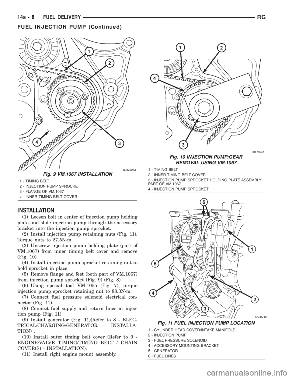
INSTALLATION
(1) Loosen bolt in center of injection pump holding
plate and slide injection pump through the accessory
bracket into the injection pump sprocket.
(2) Install injection pump retaining nuts (Fig. 11).
Torque nuts to 27.5N´m.
(3) Unscrew injection pump holding plate (part of
VM.1067) from inner timing belt cover and remove
(Fig. 10).
(4) Install injection pump sprocket retaining nut to
hold sprocket in place.
(5) Remove flange and feet (both part of VM.1067)
from injection pump sprocket (Fig. 9) (Fig. 8).
(6) Using special tool VM.1055 (Fig. 7), torque
injection pump sprocket retaining nut to 88.3N´m.
(7) Connect fuel pressure solenoid electrical con-
nector (Fig. 11).
(8) Connect fuel supply and return lines at injec-
tion pump (Fig. 11).
(9) Install generator (Fig. 11)(Refer to 8 - ELEC-
TRICAL/CHARGING/GENERATOR - INSTALLA-
TION) .
(10) Install outer timing belt cover (Refer to 9 -
ENGINE/VALVE TIMING/TIMING BELT / CHAIN
COVER(S) - INSTALLATION).
(11) Install right engine mount assembly.
Fig. 9 VM.1067 INSTALLATION
1 - TIMING BELT
2 - INJECTION PUMP SPROCKET
3 - FLANGE OF VM.1067
4 - INNER TIMING BELT COVER
Fig. 10 INJECTION PUMP/GEAR
REMOVAL USING VM.1067
1 - TIMING BELT
2 - INNER TIMING BELT COVER
3 - INJECTION PUMP SPROCKET HOLDING PLATE ASSEMBLY
PART OF VM.1067
4 - INJECTION PUMP SPROCKET
Fig. 11 FUEL INJECTION PUMP LOCATION
1 - CYLINDER HEAD COVER/INTAKE MANIFOLD
2 - INJECTION PUMP
3 - FUEL PRESSURE SOLENOID
4 - ACCESSORY MOUNTING BRACKET
5 - GENERATOR
6 - FUEL LINES
14a - 8 FUEL DELIVERYRG
FUEL INJECTION PUMP (Continued)
Page 2920 of 4284
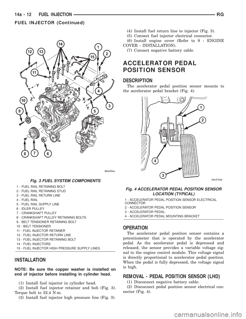
INSTALLATION
NOTE: Be sure the copper washer is installed on
end of injector before installing in cylinder head.
(1) Install fuel injector in cylinder head.
(2) Install fuel injector retainer and bolt (Fig. 3).
Torque bolt to 32.4 N´m.
(3) Install fuel injector high pressure line (Fig. 3).(4) Install fuel return line to injector (Fig. 3).
(5) Connect fuel injector electrical connector.
(6) Install engine cover (Refer to 9 - ENGINE
COVER - INSTALLATION).
(7) Connect negative battery cable.
ACCELERATOR PEDAL
POSITION SENSOR
DESCRIPTION
The accelerator pedal position sensor mounts to
the accelerator pedal bracket (Fig. 4).
OPERATION
The accelerator pedal position sensor contains a
potentiometer that is operated by the accelerator
pedal. As the accelerator pedal is depressed and
released, the sensor provides a variable voltage sig-
nal to the engine control module. This voltage signal
is directly proportional to accelerator pedal position.
When the pedal is fully depressed, the voltage signal
is high.
REMOVAL - PEDAL POSITION SENSOR (LHD)
(1) Disconnect negative battery cable.
(2) Disconnect pedal position sensor electrical con-
nector (Fig. 4).
Fig. 3 FUEL SYSTEM COMPONENTS
1 - FUEL RAIL RETAINING BOLT
2 - FUEL RAIL RETAINING STUD
3 - FUEL RAIL RETURN LINE
4 - FUEL RAIL
5 - FUEL RAIL SUPPLY LINE
6 - IDLER PULLEY
7 - CRANKSHAFT PULLEY
8 - CRANKSHAFT PULLEY RETAINING BOLTS
9 - BELT TENSIONER RETAINING BOLT
10 - BELT TENSIONER
11 - FUEL INJECTOR RETAINER
12 - FUEL INJECTOR RETURN LINE
13 - FUEL INJECTOR RETAINING BOLT
14 - FUEL INJECTORS
15 - FUEL INJECTOR HIGH PRESSURE SUPPLY LINESFig. 4 ACCELERATOR PEDAL POSITION SENSOR
LOCATION (TYPICAL)
1 - ACCELERATOR PEDAL POSITION SENSOR ELECTRICAL
CONNECTOR
2 - ACCELERATOR PEDAL POSITION SENSOR
3 - ACCELERATOR PEDAL
4 - ACCELERATOR PEDAL MOUNTING BRACKET
14a - 12 FUEL INJECTIONRG
FUEL INJECTOR (Continued)