2001 CHRYSLER VOYAGER fuel pump
[x] Cancel search: fuel pumpPage 1257 of 4284
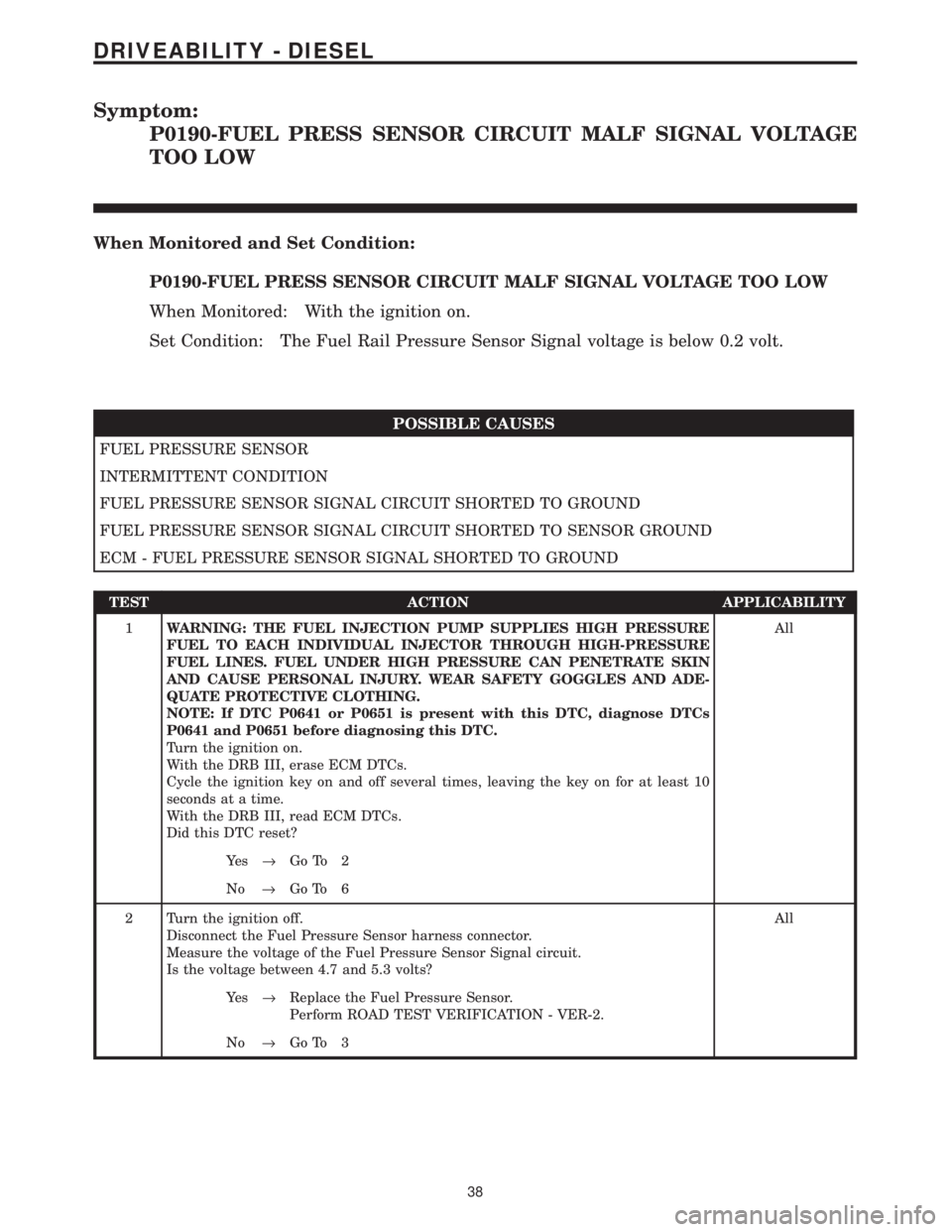
Symptom:
P0190-FUEL PRESS SENSOR CIRCUIT MALF SIGNAL VOLTAGE
TOO LOW
When Monitored and Set Condition:
P0190-FUEL PRESS SENSOR CIRCUIT MALF SIGNAL VOLTAGE TOO LOW
When Monitored: With the ignition on.
Set Condition: The Fuel Rail Pressure Sensor Signal voltage is below 0.2 volt.
POSSIBLE CAUSES
FUEL PRESSURE SENSOR
INTERMITTENT CONDITION
FUEL PRESSURE SENSOR SIGNAL CIRCUIT SHORTED TO GROUND
FUEL PRESSURE SENSOR SIGNAL CIRCUIT SHORTED TO SENSOR GROUND
ECM - FUEL PRESSURE SENSOR SIGNAL SHORTED TO GROUND
TEST ACTION APPLICABILITY
1WARNING: THE FUEL INJECTION PUMP SUPPLIES HIGH PRESSURE
FUEL TO EACH INDIVIDUAL INJECTOR THROUGH HIGH-PRESSURE
FUEL LINES. FUEL UNDER HIGH PRESSURE CAN PENETRATE SKIN
AND CAUSE PERSONAL INJURY. WEAR SAFETY GOGGLES AND ADE-
QUATE PROTECTIVE CLOTHING.
NOTE: If DTC P0641 or P0651 is present with this DTC, diagnose DTCs
P0641 and P0651 before diagnosing this DTC.
Turn the ignition on.
With the DRB III, erase ECM DTCs.
Cycle the ignition key on and off several times, leaving the key on for at least 10
seconds at a time.
With the DRB III, read ECM DTCs.
Did this DTC reset?All
Ye s®Go To 2
No®Go To 6
2 Turn the ignition off.
Disconnect the Fuel Pressure Sensor harness connector.
Measure the voltage of the Fuel Pressure Sensor Signal circuit.
Is the voltage between 4.7 and 5.3 volts?All
Ye s®Replace the Fuel Pressure Sensor.
Perform ROAD TEST VERIFICATION - VER-2.
No®Go To 3
38
DRIVEABILITY - DIESEL
Page 1259 of 4284
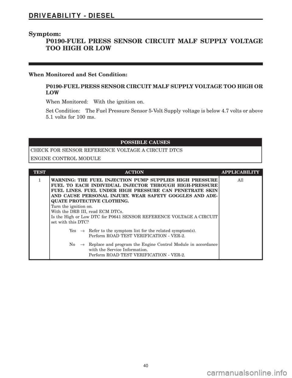
Symptom:
P0190-FUEL PRESS SENSOR CIRCUIT MALF SUPPLY VOLTAGE
TOO HIGH OR LOW
When Monitored and Set Condition:
P0190-FUEL PRESS SENSOR CIRCUIT MALF SUPPLY VOLTAGE TOO HIGH OR
LOW
When Monitored: With the ignition on.
Set Condition: The Fuel Pressure Sensor 5-Volt Supply voltage is below 4.7 volts or above
5.1 volts for 100 ms.
POSSIBLE CAUSES
CHECK FOR SENSOR REFERENCE VOLTAGE A CIRCUIT DTCS
ENGINE CONTROL MODULE
TEST ACTION APPLICABILITY
1WARNING: THE FUEL INJECTION PUMP SUPPLIES HIGH PRESSURE
FUEL TO EACH INDIVIDUAL INJECTOR THROUGH HIGH-PRESSURE
FUEL LINES. FUEL UNDER HIGH PRESSURE CAN PENETRATE SKIN
AND CAUSE PERSONAL INJURY. WEAR SAFETY GOGGLES AND ADE-
QUATE PROTECTIVE CLOTHING.
Turn the ignition on.
With the DRB III, read ECM DTCs.
Is the High or Low DTC for P0641 SENSOR REFERENCE VOLTAGE A CIRCUIT
set with this DTC?All
Ye s®Refer to the symptom list for the related symptom(s).
Perform ROAD TEST VERIFICATION - VER-2.
No®Replace and program the Engine Control Module in accordance
with the Service Information.
Perform ROAD TEST VERIFICATION - VER-2.
40
DRIVEABILITY - DIESEL
Page 1348 of 4284
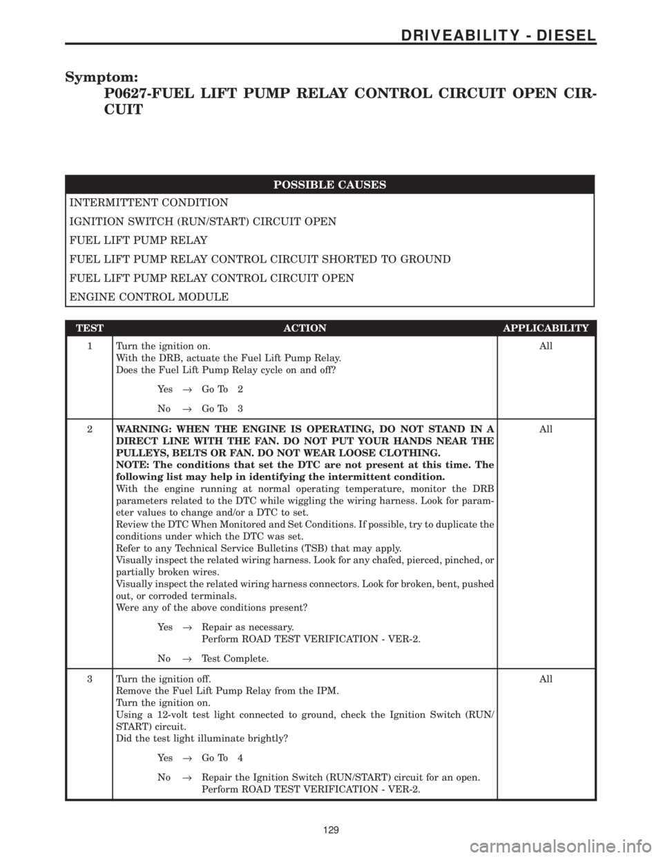
Symptom:
P0627-FUEL LIFT PUMP RELAY CONTROL CIRCUIT OPEN CIR-
CUIT
POSSIBLE CAUSES
INTERMITTENT CONDITION
IGNITION SWITCH (RUN/START) CIRCUIT OPEN
FUEL LIFT PUMP RELAY
FUEL LIFT PUMP RELAY CONTROL CIRCUIT SHORTED TO GROUND
FUEL LIFT PUMP RELAY CONTROL CIRCUIT OPEN
ENGINE CONTROL MODULE
TEST ACTION APPLICABILITY
1 Turn the ignition on.
With the DRB, actuate the Fuel Lift Pump Relay.
Does the Fuel Lift Pump Relay cycle on and off?All
Ye s®Go To 2
No®Go To 3
2WARNING: WHEN THE ENGINE IS OPERATING, DO NOT STAND IN A
DIRECT LINE WITH THE FAN. DO NOT PUT YOUR HANDS NEAR THE
PULLEYS, BELTS OR FAN. DO NOT WEAR LOOSE CLOTHING.
NOTE: The conditions that set the DTC are not present at this time. The
following list may help in identifying the intermittent condition.
With the engine running at normal operating temperature, monitor the DRB
parameters related to the DTC while wiggling the wiring harness. Look for param-
eter values to change and/or a DTC to set.
Review the DTC When Monitored and Set Conditions. If possible, try to duplicate the
conditions under which the DTC was set.
Refer to any Technical Service Bulletins (TSB) that may apply.
Visually inspect the related wiring harness. Look for any chafed, pierced, pinched, or
partially broken wires.
Visually inspect the related wiring harness connectors. Look for broken, bent, pushed
out, or corroded terminals.
Were any of the above conditions present?All
Ye s®Repair as necessary.
Perform ROAD TEST VERIFICATION - VER-2.
No®Test Complete.
3 Turn the ignition off.
Remove the Fuel Lift Pump Relay from the IPM.
Turn the ignition on.
Using a 12-volt test light connected to ground, check the Ignition Switch (RUN/
START) circuit.
Did the test light illuminate brightly?All
Ye s®Go To 4
No®Repair the Ignition Switch (RUN/START) circuit for an open.
Perform ROAD TEST VERIFICATION - VER-2.
129
DRIVEABILITY - DIESEL
Page 1349 of 4284
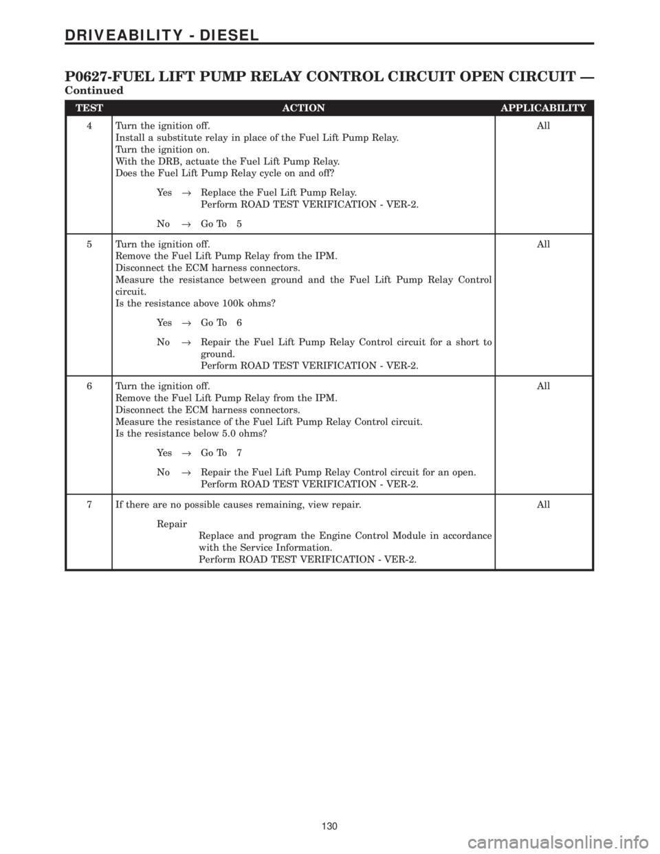
TEST ACTION APPLICABILITY
4 Turn the ignition off.
Install a substitute relay in place of the Fuel Lift Pump Relay.
Turn the ignition on.
With the DRB, actuate the Fuel Lift Pump Relay.
Does the Fuel Lift Pump Relay cycle on and off?All
Ye s®Replace the Fuel Lift Pump Relay.
Perform ROAD TEST VERIFICATION - VER-2.
No®Go To 5
5 Turn the ignition off.
Remove the Fuel Lift Pump Relay from the IPM.
Disconnect the ECM harness connectors.
Measure the resistance between ground and the Fuel Lift Pump Relay Control
circuit.
Is the resistance above 100k ohms?All
Ye s®Go To 6
No®Repair the Fuel Lift Pump Relay Control circuit for a short to
ground.
Perform ROAD TEST VERIFICATION - VER-2.
6 Turn the ignition off.
Remove the Fuel Lift Pump Relay from the IPM.
Disconnect the ECM harness connectors.
Measure the resistance of the Fuel Lift Pump Relay Control circuit.
Is the resistance below 5.0 ohms?All
Ye s®Go To 7
No®Repair the Fuel Lift Pump Relay Control circuit for an open.
Perform ROAD TEST VERIFICATION - VER-2.
7 If there are no possible causes remaining, view repair. All
Repair
Replace and program the Engine Control Module in accordance
with the Service Information.
Perform ROAD TEST VERIFICATION - VER-2.
130
DRIVEABILITY - DIESEL
P0627-FUEL LIFT PUMP RELAY CONTROL CIRCUIT OPEN CIRCUIT Ð
Continued
Page 1350 of 4284
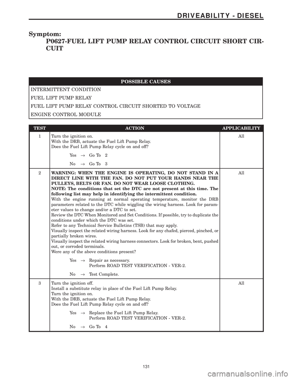
Symptom:
P0627-FUEL LIFT PUMP RELAY CONTROL CIRCUIT SHORT CIR-
CUIT
POSSIBLE CAUSES
INTERMITTENT CONDITION
FUEL LIFT PUMP RELAY
FUEL LIFT PUMP RELAY CONTROL CIRCUIT SHORTED TO VOLTAGE
ENGINE CONTROL MODULE
TEST ACTION APPLICABILITY
1 Turn the ignition on.
With the DRB, actuate the Fuel Lift Pump Relay.
Does the Fuel Lift Pump Relay cycle on and off?All
Ye s®Go To 2
No®Go To 3
2WARNING: WHEN THE ENGINE IS OPERATING, DO NOT STAND IN A
DIRECT LINE WITH THE FAN. DO NOT PUT YOUR HANDS NEAR THE
PULLEYS, BELTS OR FAN. DO NOT WEAR LOOSE CLOTHING.
NOTE: The conditions that set the DTC are not present at this time. The
following list may help in identifying the intermittent condition.
With the engine running at normal operating temperature, monitor the DRB
parameters related to the DTC while wiggling the wiring harness. Look for param-
eter values to change and/or a DTC to set.
Review the DTC When Monitored and Set Conditions. If possible, try to duplicate the
conditions under which the DTC was set.
Refer to any Technical Service Bulletins (TSB) that may apply.
Visually inspect the related wiring harness. Look for any chafed, pierced, pinched, or
partially broken wires.
Visually inspect the related wiring harness connectors. Look for broken, bent, pushed
out, or corroded terminals.
Were any of the above conditions present?All
Ye s®Repair as necessary.
Perform ROAD TEST VERIFICATION - VER-2.
No®Test Complete.
3 Turn the ignition off.
Install a substitute relay in place of the Fuel Lift Pump Relay.
Turn the ignition on.
With the DRB, actuate the Fuel Lift Pump Relay.
Does the Fuel Lift Pump Relay cycle on and off?All
Ye s®Replace the Fuel Lift Pump Relay.
Perform ROAD TEST VERIFICATION - VER-2.
No®Go To 4
131
DRIVEABILITY - DIESEL
Page 1351 of 4284
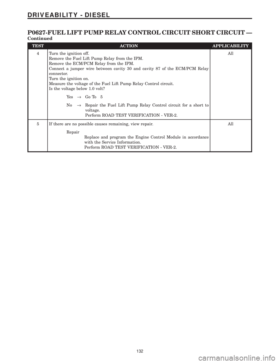
TEST ACTION APPLICABILITY
4 Turn the ignition off.
Remove the Fuel Lift Pump Relay from the IPM.
Remove the ECM/PCM Relay from the IPM.
Connect a jumper wire between cavity 30 and cavity 87 of the ECM/PCM Relay
connector.
Turn the ignition on.
Measure the voltage of the Fuel Lift Pump Relay Control circuit.
Is the voltage below 1.0 volt?All
Ye s®Go To 5
No®Repair the Fuel Lift Pump Relay Control circuit for a short to
voltage.
Perform ROAD TEST VERIFICATION - VER-2.
5 If there are no possible causes remaining, view repair. All
Repair
Replace and program the Engine Control Module in accordance
with the Service Information.
Perform ROAD TEST VERIFICATION - VER-2.
132
DRIVEABILITY - DIESEL
P0627-FUEL LIFT PUMP RELAY CONTROL CIRCUIT SHORT CIRCUIT Ð
Continued
Page 1375 of 4284
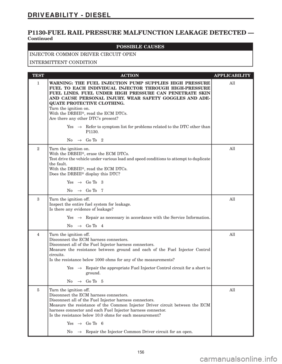
POSSIBLE CAUSES
INJECTOR COMMON DRIVER CIRCUIT OPEN
INTERMITTENT CONDITION
TEST ACTION APPLICABILITY
1WARNING: THE FUEL INJECTION PUMP SUPPLIES HIGH PRESSURE
FUEL TO EACH INDIVIDUAL INJECTOR THROUGH HIGH-PRESSURE
FUEL LINES. FUEL UNDER HIGH PRESSURE CAN PENETRATE SKIN
AND CAUSE PERSONAL INJURY. WEAR SAFETY GOGGLES AND ADE-
QUATE PROTECTIVE CLOTHING.
Turn the ignition on.
With the DRBIIIt, read the ECM DTCs.
Are there any other DTC's present?All
Ye s®Refer to symptom list for problems related to the DTC other than
P1130.
No®Go To 2
2 Turn the ignition on.
With the DRBIIIt, erase the ECM DTCs.
Test drive the vehicle under various load and speed conditions to attempt to duplicate
the fault.
With the DRBIIIt, read the ECM DTCs.
Does the DRBIIItdisplay this DTC?All
Ye s®Go To 3
No®Go To 7
3 Turn the ignition off.
Inspect the entire fuel system for leakage.
Is there any evidence of leakage?All
Ye s®Repair as necessary in accordance with the Service Information.
No®Go To 4
4 Turn the ignition off.
Disconnect the ECM harness connectors.
Disconnect all of the Fuel Injector harness connectors.
Measure the resistance between ground and each of the Fuel Injector Control
circuits.
Is the resistance below 1000 ohms for any of the measurements?All
Ye s®Repair the appropriate Fuel Injector Control circuit for a short to
ground.
No®Go To 5
5 Turn the ignition off.
Disconnect the ECM harness connectors.
Disconnect all of the Fuel Injector harness connectors.
Measure the resistance of the Common Injector Driver circuit between the ECM
harness connector and each Fuel Injector harness connector.
Is the resistance below 10.0 ohms for each measurement?All
Ye s®Go To 6
No®Repair the Injector Common Driver circuit for an open.
156
DRIVEABILITY - DIESEL
P1130-FUEL RAIL PRESSURE MALFUNCTION LEAKAGE DETECTED Ð
Continued
Page 1378 of 4284
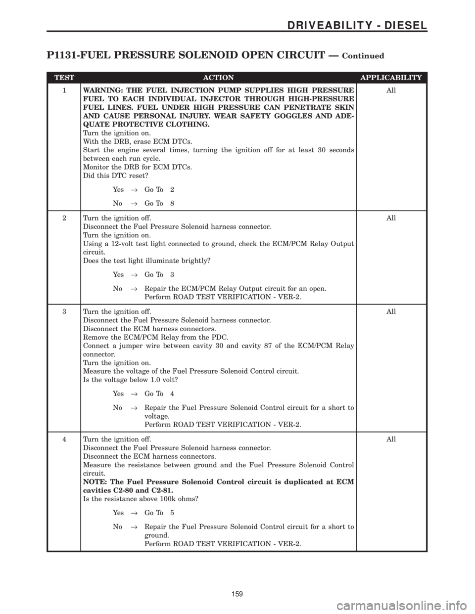
TEST ACTION APPLICABILITY
1WARNING: THE FUEL INJECTION PUMP SUPPLIES HIGH PRESSURE
FUEL TO EACH INDIVIDUAL INJECTOR THROUGH HIGH-PRESSURE
FUEL LINES. FUEL UNDER HIGH PRESSURE CAN PENETRATE SKIN
AND CAUSE PERSONAL INJURY. WEAR SAFETY GOGGLES AND ADE-
QUATE PROTECTIVE CLOTHING.
Turn the ignition on.
With the DRB, erase ECM DTCs.
Start the engine several times, turning the ignition off for at least 30 seconds
between each run cycle.
Monitor the DRB for ECM DTCs.
Did this DTC reset?All
Ye s®Go To 2
No®Go To 8
2 Turn the ignition off.
Disconnect the Fuel Pressure Solenoid harness connector.
Turn the ignition on.
Using a 12-volt test light connected to ground, check the ECM/PCM Relay Output
circuit.
Does the test light illuminate brightly?All
Ye s®Go To 3
No®Repair the ECM/PCM Relay Output circuit for an open.
Perform ROAD TEST VERIFICATION - VER-2.
3 Turn the ignition off.
Disconnect the Fuel Pressure Solenoid harness connector.
Disconnect the ECM harness connectors.
Remove the ECM/PCM Relay from the PDC.
Connect a jumper wire between cavity 30 and cavity 87 of the ECM/PCM Relay
connector.
Turn the ignition on.
Measure the voltage of the Fuel Pressure Solenoid Control circuit.
Is the voltage below 1.0 volt?All
Ye s®Go To 4
No®Repair the Fuel Pressure Solenoid Control circuit for a short to
voltage.
Perform ROAD TEST VERIFICATION - VER-2.
4 Turn the ignition off.
Disconnect the Fuel Pressure Solenoid harness connector.
Disconnect the ECM harness connectors.
Measure the resistance between ground and the Fuel Pressure Solenoid Control
circuit.
NOTE: The Fuel Pressure Solenoid Control circuit is duplicated at ECM
cavities C2-80 and C2-81.
Is the resistance above 100k ohms?All
Ye s®Go To 5
No®Repair the Fuel Pressure Solenoid Control circuit for a short to
ground.
Perform ROAD TEST VERIFICATION - VER-2.
159
DRIVEABILITY - DIESEL
P1131-FUEL PRESSURE SOLENOID OPEN CIRCUIT ÐContinued