2001 CHRYSLER VOYAGER traction control
[x] Cancel search: traction controlPage 1199 of 4284
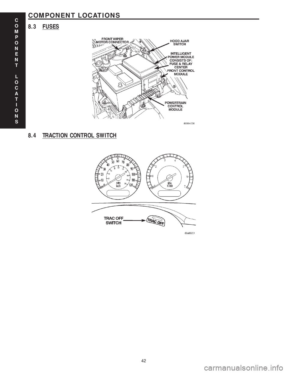
8.3 FUSES
8.4 TRACTION CONTROL SWITCH
C
O
M
P
O
N
E
N
T
L
O
C
A
T
I
O
N
S
42
COMPONENT LOCATIONS
Page 1200 of 4284
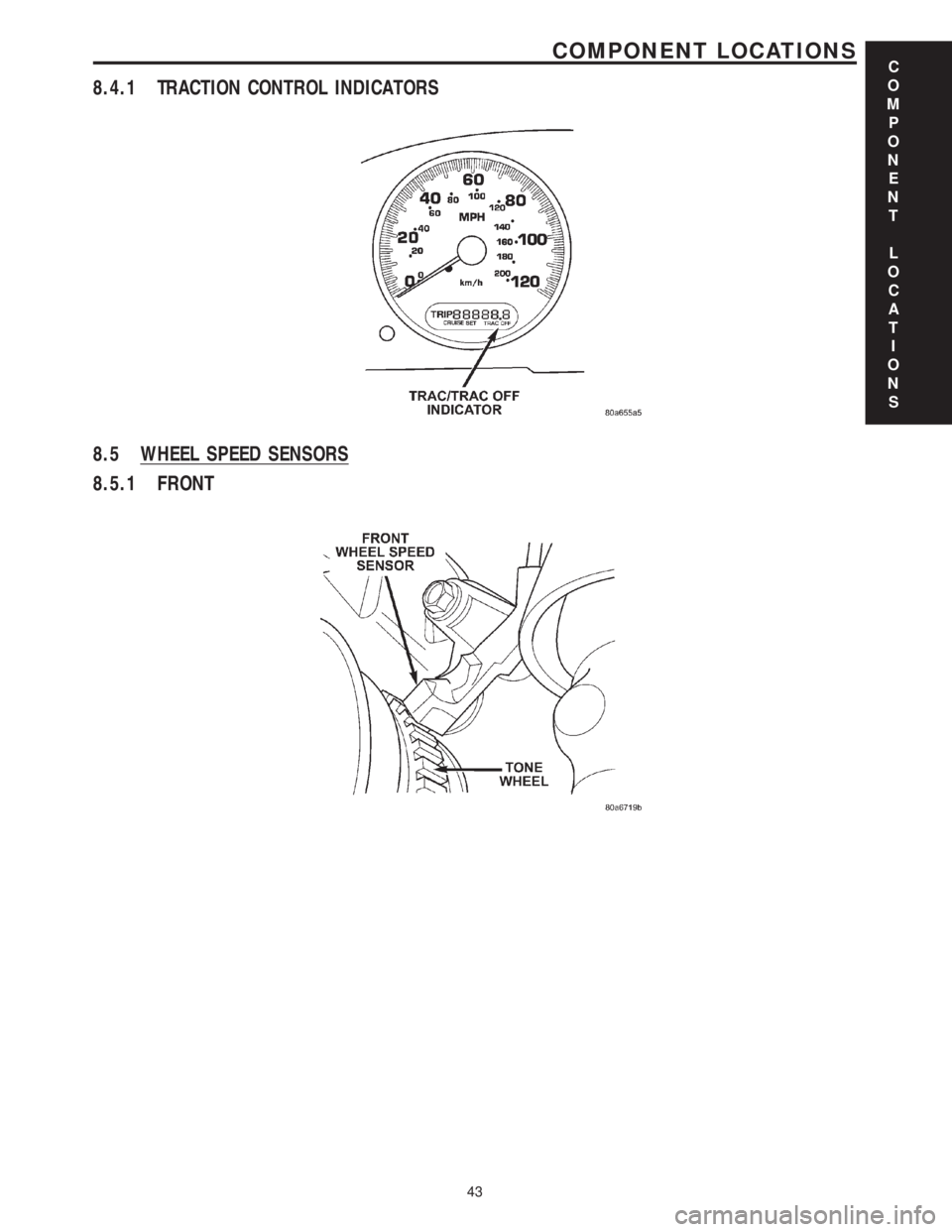
8.4.1 TRACTION CONTROL INDICATORS
8.5 WHEEL SPEED SENSORS
8.5.1 FRONT
C
O
M
P
O
N
E
N
T
L
O
C
A
T
I
O
N
S
43
COMPONENT LOCATIONS
Page 1210 of 4284
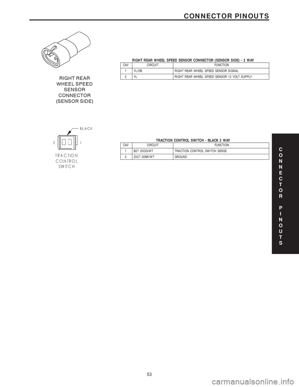
RIGHT REAR WHEEL SPEED SENSOR CONNECTOR (SENSOR SIDE)-2WAYCAV CIRCUIT FUNCTION
1 YL/DB RIGHT REAR WHEEL SPEED SENSOR SIGNAL
2 YL RIGHT REAR WHEEL SPEED SENSOR 12 VOLT SUPPLY
TRACTION CONTROL SWITCH - BLACK 2 WAYCAV CIRCUIT FUNCTION
1 B27 20DG/WT TRACTION CONTROL SWITCH SENSE
2 Z427 20BK/WT GROUNDC
O
N
N
E
C
T
O
R
P
I
N
O
U
T
S
53
CONNECTOR PINOUTS
Page 1602 of 4284
REAR DRIVELINE MODULE
TABLE OF CONTENTS
page page
REAR DRIVELINE MODULE
DESCRIPTION...........................26
OPERATION.............................26
DIAGNOSIS AND TESTING.................27
REAR DRIVELINE MODULE NOISE.........27
REAR DRIVELINE MODULE OPERATION....29
REMOVAL..............................29
DISASSEMBLY...........................30
ASSEMBLY.............................32
INSTALLATION...........................36
SPECIFICATIONS........................37
SPECIAL TOOLS.........................37
BI-DIRECTIONAL OVERRUNNING CLUTCH
DESCRIPTION...........................37
OPERATION.............................38
DIFFERENTIAL ASSEMBLY
DESCRIPTION...........................43
OPERATION.............................43FLUID - DIFFERENTIAL ASSEMBLY
STANDARD PROCEDURE..................44
DIFFERENTIAL ASSEMBLY FLUID CHANGE . . 44
FLUID
STANDARD PROCEDURE..................44
OVERRUNNING CLUTCH HOUSING FLUID
CHANGE..............................44
VISCOUS COUPLER
DESCRIPTION...........................45
OPERATION.............................45
TORQUE ARM
REMOVAL..............................47
INSTALLATION...........................47
INPUT FLANGE SEAL
REMOVAL..............................47
INSTALLATION...........................47
OUTPUT FLANGE SEAL
REMOVAL..............................49
INSTALLATION...........................50
REAR DRIVELINE MODULE
DESCRIPTION
The rear driveline module assembly (Fig. 1) con-
sists of four main components:
²Bi-Directional Overrunning Clutch (BOC)
²Viscous Coupling
²Differential Assembly
²Torque Arm
The viscous coupling and bi-directional overrun-
ning clutch are contained within an overrunning
clutch housing, which fastens to the differential
assembly. The overrunning clutch housing and differ-
ential assembly have unique fluid sumps, each
requiring their own type and capacity of fluid. The
overrunning clutch housing requires MopartATF+4
(Automatic Transmission FluidÐType 9602) or equiv-
alent. The differential assembly requires
Driveline module service is limited to the following
components:
²Differential Assembly (serviced only as assem-
bly)
²Viscous Coupling
²Bi-Directional Overrunning Clutch (BOC)
²Overrunning Clutch Housing
²Seals (Input Flange, Output Flange, Overrun-
ning Clutch Housing O-rings)
²Input Flange/Shield²Torque Arm
²Vents
²FastenersOPERATION
The primary benefits of All Wheel Drive are:
²Superior straight line acceleration, and corner-
ing on all surfaces
²Better traction and handling under adverse con-
ditions, resulting in improved hill climbing ability
and safer driving.
The heart of the system is an inter-axle viscous
coupling. The vehicle retains predominantly front-
wheel drive characteristics, but the All Wheel Drive
capability takes effect when the front wheels start to
slip. Under normal level road, straight line driving,
100% of the torque is allocated to the front wheels.
The viscous coupling controls and distributes torque/
power to the rear wheels. The viscous coupling trans-
mits torque to the rear wheels in proportion of the
amount of the slippage at the front wheels. Thais
variable torque distribution is automatic with no
driver inputs required. The coupling is similar to a
multi-plate clutch. It consists of a series of closely
spaced discs, which are alternately connected to the
front and rear drive units. The unit is totally sealed
and partially filled with silicone fluid. There is no
3 - 26 REAR DRIVELINE MODULERS
Page 1623 of 4284
When a high speed difference (shear) occurs
because of loss of traction (one axle spinning faster
than the other), the silicone fluid expands as it heats
from this shearing. When the silicone expands to fill
the viscous coupler completely, this pressure differ-
ence is high enough to squeeze each pair of plates
together. The resulting hump torque is up to 8 times
higher than the shear torque. When the viscous cou-
pler is in the hump mode, it does not lock the axles
(undifferentiated 4-Wheel Drive). It controls the
amount of slippage while delivering maximum power
to the axle having greatest traction. Once the speed
difference equalizes the fluid and plates cool down
and the viscous coupler goes back to the shear mode.
TORQUE ARM
REMOVAL
(1) Raise vehicle on hoist.
(2) Remove rear driveline module assembly. (Refer
to 3 - DIFFERENTIAL & DRIVELINE/REAR DRIV-
ELINE MODULE - REMOVAL)
(3) Remove six torque arm-to-differential assembly
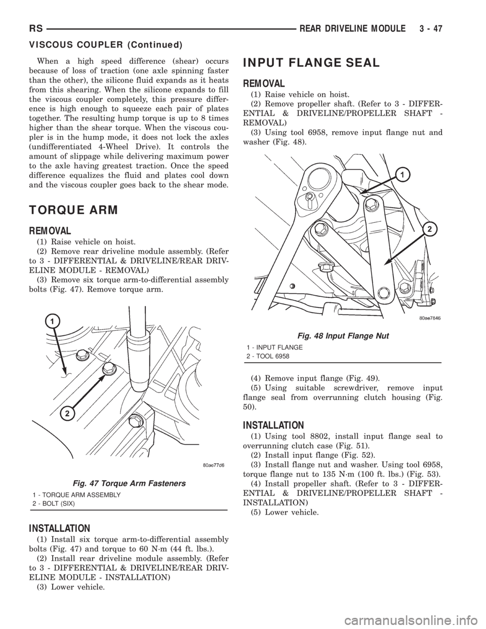
bolts (Fig. 47). Remove torque arm.
INSTALLATION
(1) Install six torque arm-to-differential assembly
bolts (Fig. 47) and torque to 60 N´m (44 ft. lbs.).
(2) Install rear driveline module assembly. (Refer
to 3 - DIFFERENTIAL & DRIVELINE/REAR DRIV-
ELINE MODULE - INSTALLATION)
(3) Lower vehicle.
INPUT FLANGE SEAL
REMOVAL
(1) Raise vehicle on hoist.
(2) Remove propeller shaft. (Refer to 3 - DIFFER-
ENTIAL & DRIVELINE/PROPELLER SHAFT -
REMOVAL)
(3) Using tool 6958, remove input flange nut and
washer (Fig. 48).
(4) Remove input flange (Fig. 49).
(5) Using suitable screwdriver, remove input
flange seal from overrunning clutch housing (Fig.
50).
INSTALLATION
(1) Using tool 8802, install input flange seal to
overrunning clutch case (Fig. 51).
(2) Install input flange (Fig. 52).
(3) Install flange nut and washer. Using tool 6958,
torque flange nut to 135 N´m (100 ft. lbs.) (Fig. 53).
(4) Install propeller shaft. (Refer to 3 - DIFFER-
ENTIAL & DRIVELINE/PROPELLER SHAFT -
INSTALLATION)
(5) Lower vehicle.
Fig. 47 Torque Arm Fasteners
1 - TORQUE ARM ASSEMBLY
2 - BOLT (SIX)
Fig. 48 Input Flange Nut
1 - INPUT FLANGE
2 - TOOL 6958
RSREAR DRIVELINE MODULE3-47
VISCOUS COUPLER (Continued)
Page 1628 of 4284
JUNCTION BLOCK
DESCRIPTION...........................32
OPERATION.............................32
REMOVAL..............................32
INSTALLATION...........................33
MASTER CYLINDER
DESCRIPTION...........................33
OPERATION.............................34
STANDARD PROCEDURE..................34
MASTER CYLINDER BLEEDING...........34
REMOVAL..............................34
DISASSEMBLY...........................35
ASSEMBLY.............................36
INSTALLATION...........................36
POWER BRAKE BOOSTER
DESCRIPTION...........................37
OPERATION.............................37
DIAGNOSIS AND TESTING.................38
POWER BRAKE BOOSTER...............38
REMOVAL..............................38
INSTALLATION...........................40
PROPORTIONING VALVE
DESCRIPTION...........................41
OPERATION.............................42
DIAGNOSIS AND TESTING.................42
PROPORTIONING VALVE (HEIGHT
SENSING).............................42
REMOVAL..............................43
INSTALLATION...........................43
ROTORS
DIAGNOSIS AND TESTING.................44BRAKE ROTOR........................44
STANDARD PROCEDURE..................47
BRAKE ROTOR MACHINING..............47
REMOVAL..............................48
INSTALLATION...........................48
SUPPORT PLATE - DRUM BRAKE
REMOVAL..............................48
INSTALLATION...........................49
WHEEL CYLINDERS
REMOVAL..............................50
INSPECTION............................50
INSTALLATION...........................50
PARKING BRAKE
DESCRIPTION...........................50
OPERATION.............................51
STANDARD PROCEDURE..................51
PARKING BRAKE AUTOMATIC ADJUSTER
MECHANISM RELEASE..................51
PARKING BRAKE AUTOMATIC ADJUSTER
RESET...............................51
LEVER - PARKING BRAKE
REMOVAL..............................52
INSTALLATION...........................53
SHOES - PARKING BRAKE
REMOVAL..............................53
INSTALLATION...........................58
ADJUSTMENTS..........................59
CABLES - PARKING BRAKE
REMOVAL..............................61
INSTALLATION...........................65
ADJUSTMENTS..........................66
BRAKES - BASE
DESCRIPTION - BASE BRAKES
The base brake system consists of the following
components:
²Brake pedal
²Power brake booster
²Master cylinder
²Brake tubes and hoses
²Proportioning valve (non-ABS vehicles only)
²Disc brakes
²Drum brakes
²Brake lamp switch
²Brake fluid level switch
²Parking brakes
Front disc brakes control the braking of the front
wheels; rear braking is controlled by rear drum
brakes or rear disc brakes depending on options.
The hydraulic brake system is diagonally split on
both the non-antilock braking systems and antilock
braking systems. That means the left front and right
rear brakes are on one hydraulic circuit and the right
front and left rear are on the other.For information on the brake lamp switch, (Refer
to 8 - ELECTRICAL/LAMPS/LIGHTING - EXTERI-
OR/BRAKE LAMP SWITCH - DESCRIPTION)
Vehicles equipped with the optional antilock brake
system (ABS) use a system designated Mark 20e. It
is available with or without traction control. This
system shares most base brake hardware used on
vehicles without ABS. ABS components are described
in detail in ANTILOCK BRAKE SYSTEM.
OPERATION - BASE BRAKES
When a vehicle needs to be stopped, the driver
applies the brake pedal. The brake pedal pushes the
input rod of the power brake booster into the booster.
The booster uses vacuum to ease pedal effort as force
is transferred through the booster to the master cyl-
inder. The booster's output rod pushes in the master
cylinder's primary and secondary pistons applying
hydraulic pressure through the chassis brake tubes
to the brakes at each tire and wheel assembly.
The parking brakes are foot-operated. When
applied, the parking brake lever pulls on cables that
actuate brake shoes at each rear wheel. These shoes
come in contact with a hub mounted drum (drum for
5 - 2 BRAKES - BASERS
Page 1660 of 4284
For information on master cylinder application,
bore and type, view the following table:
BRAKE SYSTEMMASTER CYLINDER
BORE/TYPE
Disc/Drum - ABS23.8 mm Conventional
Compensating Port
Disc/Drum - Non-ABS23.8 mm Conventional
Compensating Port
Disc/Disc - ABS25.4 mm (1-1/16 in.)
Conventional
Compensating Port
Disc/Disc ABS With
Traction Control25.4 mm (1-1/16 in.) Dual
Center Port
CAUTION: When replacing a master cylinder, be
sure to use the correct master cylinder for the type
of brake system the vehicle is equipped with.
The body of the master cylinder is an anodized alu-
minum casting. It has a machined bore to accept the
master cylinder pistons and threaded ports with
seats for the hydraulic brake line connections.
The brake fluid reservoir is mounted on the top of
the master cylinder. It is made of a see-through
polypropylene type plastic for easy fluid level view-
ing. A brake fluid level switch is attached to the
brake fluid reservoir.
The master cylinder is not a repairable component
and must be replaced if diagnosed to be functioning
improperly. The brake fluid reservoir and brake fluid
level switch can be replaced separately.
CAUTION: Do not hone the bore of the cylinder as
this will remove the anodized surface from the bore.
OPERATION
When the brake pedal is depressed, the master cyl-
inder primary and secondary pistons apply brake
pressure through the chassis tubes to the brakes at
each tire and wheel assembly.
The master cylinder primary outlet port supplies
hydraulic pressure to the right front and left rear
brakes. The secondary outlet port supplies hydraulic
pressure to the left front and right rear brakes.
STANDARD PROCEDURE - MASTER CYLINDER
BLEEDING
CAUTION: When clamping master cylinder in vise,
only clamp master cylinder by its mounting flange,
do not clamp on primary piston, seal or body of
master cylinder.(1) Clamp the master cylinder in a vise using only
the mounting flange.
NOTE: Two different size bleeding tubes need to be
used depending on which type of master cylinder
the vehicle is equipped with. Vehicles equipped
with traction control have different size brake tubes
and nuts at the master cylinder than the non-trac-
tion control equipped vehicles. Be sure the correct
size bleeding tubes are used when bleeding the
master cylinder.
(2) Thread Bleeding Tubes, Special Tool 8358, for a
non-traction control master cylinder or Special Tool
8129 for a traction control master cylinder into mas-
ter cylinder primary and secondary ports. Position
outlet ends of bleeding tubes in reservoir with the
outlets below surface of brake fluid when reservoir is
filled to its proper level.
(3) Fill brake fluid reservoir with Mopartbrake
fluid or equivalent conforming to DOT 3 (DOT 4 and
DOT 4+ are acceptable) specifications.
(4) Using a wooden dowel, depress push rod slowly,
and then allow pistons to return to released position.
Repeat several times until all air bubbles are
expelled from master cylinder.
(5) Remove bleeding tubes from master cylinder
outlet ports, and then plug outlet ports and install
fill cap on reservoir.
(6) Remove master cylinder from vise.
(7) Install the filler cap on master cylinder fluid
reservoir.
(8) Install master cylinder. (Refer to 5 - BRAKES -
BASE/HYDRAULIC/MECHANICAL/MASTER CYL-
INDER - INSTALLATION)
REMOVAL - MASTER CYLINDER
CAUTION: Vacuum in the power brake booster must
be pumped down (removed) before removing mas-
ter cylinder from power brake booster. This is nec-
essary to prevent the power brake booster from
sucking in any contamination as the master cylin-
der is removed. This can be done simply by pump-
ing the brake pedal, with the vehicle's engine not
running, until a firm feeling brake pedal is achieved.
(1) With engine not running, pump brake pedal
until a firm pedal is achieved (4-5 strokes).
(2) Disconnect negative battery terminal.
(3) Disconnect positive battery terminal.
(4) Remove battery shield.
(5) Remove nut and clamp securing battery to tray,
remove battery.
5 - 34 BRAKES - BASERS
MASTER CYLINDER (Continued)
Page 1693 of 4284
BRAKES - ABS
TABLE OF CONTENTS
page page
BRAKES - ABS
DESCRIPTION...........................67
OPERATION.............................67
CAUTION...............................69
STANDARD PROCEDURE..................70
ANTILOCK BRAKE SYSTEM BLEEDING.....70
SPECIFICATIONS........................71
FRONT WHEEL SPEED SENSOR
REMOVAL..............................71
INSTALLATION...........................71
REAR WHEEL SPEED SENSOR - AWD
REMOVAL..............................72
INSTALLATION...........................72
REAR WHEEL SPEED SENSOR - FWD
REMOVAL..............................73INSTALLATION...........................74
TONE WHEEL
INSPECTION............................74
TRACTION CONTROL SWITCH
DIAGNOSIS AND TESTING.................74
TRACTION CONTROL SWITCH............74
ICU (INTEGRATED CONTROL UNIT)
DESCRIPTION...........................75
OPERATION.............................75
REMOVAL..............................76
DISASSEMBLY...........................77
ASSEMBLY.............................77
INSTALLATION...........................77
BRAKES - ABS
DESCRIPTION - ANTILOCK BRAKE SYSTEM
This section covers the physical and operational
descriptions and the on-car service procedures for the
Mark 20e Antilock Brake System and the Mark 20e
Antilock Brake System with traction control.
The purpose of the antilock brake system (ABS) is
to prevent wheel lockup under braking conditions on
virtually any type of road surface. Antilock braking is
desirable because a vehicle that is stopped without
locking the wheels retains directional stability and
some steering capability. This allows the driver to
retain greater control of the vehicle during braking.
DESCRIPTION - ELECTRONIC BRAKE
DISTRIBUTION
Vehicles equipped with ABS use electronic brake
distribution (EBD) to balance front-to-rear braking.
The EBD is used in place of a rear proportioning
valve. The EBD system uses the ABS system to con-
trol the slip of the rear wheels in partial braking
range. The braking force of the rear wheels is con-
trolled electronically by using the inlet and outlet
valves located in the integrated control unit (ICU).
DESCRIPTION - TRACTION CONTROL SYSTEM
Traction control reduces wheel slip and maintains
traction at the driving wheels at speeds below 56
km/h (35 mph) when road surfaces are slippery. The
traction control system reduces wheel slip by braking
the wheel that is losing traction.
HYDRAULIC SHUTTLE VALVES
Two pressure relief hydraulic shuttle valves are
included on vehicles with traction control. These
valves are located inside the HCU and cannot be ser-
viced separately from the HCU.
TRACTION CONTROL LAMP
The traction control function lamp is located in the
transmission range indicator display of the instru-
ment cluster, displaying TRAC, TRAC OFF or nei-
ther depending on system mode.
The TRAC OFF lamp is controlled by a Traction
Control Off switch that is a momentary contact type
switch. The Traction Control Off switch is located on
the steering column upper shroud.
OPERATION - ANTILOCK BRAKE SYSTEM
There are a few performance characteristics of the
Mark 20e Antilock Brake System that may at first
seem abnormal, but in fact are normal. These char-
acteristics are described below.
NORMAL BRAKING
Under normal braking conditions, the ABS func-
tions the same as a standard base brake system with
a diagonally split master cylinder and conventional
vacuum assist.
ABS BRAKING
ABS operation is available at all vehicle speeds
above 3±5 mph. If a wheel locking tendency is
detected during a brake application, the brake sys-
RSBRAKES - ABS5-67