2001 CHRYSLER VOYAGER traction control
[x] Cancel search: traction controlPage 1695 of 4284
the rear brake pressure, the outlet valve is switched
off and the inlet valve is pulsed. This increases the
pressure to the rear brakes. This back-and-forth pro-
cess will continue until the required slip difference is
obtained. At the end of EBD braking (brakes
released) the fluid in the LPA drains back to the
master cylinder by switching on the outlet valve and
draining through the inlet valve check valve. At the
same time the inlet valve is switched on in case of
another brake application.
The EBD will remain functional during many ABS
fault modes. If both the red BRAKE, and amber ABS
warning indicators are illuminated, the EBD may not
be functioning.
OPERATION - TRACTION CONTROL SYSTEM
The traction control module monitors wheel speed.
During acceleration, if the module detects front
(drive) wheel slip and the brakes are not applied, the
module enters traction control mode. Traction control
operation proceeds in the following order:
(1) Close the normally open isolation valves.
(2) Start the pump/motor and supply volume and
pressure to the front (drive) hydraulic circuit. (The
pump/motor runs continuously during traction con-
trol operation.)
(3) Open and close the build and decay valves to
maintain minimum wheel slip and maximum trac-
tion.
The cycling of the build and decay valves during
traction control is similar to that during antilock
braking, except the valves work to control wheel spin
by applying the brakes, whereas the ABS function is
to control wheel skid by releasing the brakes.
If the brakes are applied at anytime during a trac-
tion control cycle, the brake lamp switch triggers the
controller to switch off traction control.
HYDRAULIC SHUTTLE VALVES
Two pressure relief hydraulic shuttle valves allow
pressure and volume to return to the master cylinder
reservoir when not consumed by the build and decay
valves. These valves are necessary because the
pump/motor supplies more volume than the system
requires.
TRACTION CONTROL LAMP
The traction control system is enabled at each igni-
tion cycle. It may be turned off by depressing the
Traction Control Off switch button when the ignition
is in the ON position. The traction control function
lamp (TRAC OFF) illuminates immediately upon
depressing the button.
The traction control function lamp illuminates dur-
ing a traction control cycle, displaying TRAC.If the CAB calculates that the brake temperatures
are high, the traction control system becomes inoper-
ative until a time-out period has elapsed. During this
ªthermo-protection mode,º the traction control func-
tion lamp illuminates TRAC OFF; note that no trou-
ble code is registered.
CAUTION
The ABS uses an electronic control module, the
CAB. This module is designed to withstand normal
current draws associated with vehicle operation.
Care must be taken to avoid overloading the CAB
circuits.
CAUTION: In testing for open or short circuits, do
not ground or apply voltage to any of the circuits
unless instructed to do so for a diagnostic proce-
dure.
CAUTION: These circuits should only be tested
using a high impedance multi-meter or the DRBIIIT
scan tool as described in this section. Power
should never be removed or applied to any control
module with the ignition in the ON position. Before
removing or connecting battery cables, fuses, or
connectors, always turn the ignition to the OFF
position.
CAUTION: The CAB 24-way connector should never
be connected or disconnected with the ignition
switch in the ON position.
CAUTION: Use only factory wiring harnesses. Do
not cut or splice wiring to the brake circuits. The
addition of aftermarket electrical equipment (car
phone, radar detector, citizen band radio, trailer
lighting, trailer brakes, etc.) on a vehicle equipped
with antilock brakes may affect the function of the
antilock brake system.
CAUTION: When performing any service procedure
on a vehicle equipped with ABS, do not apply a
12-volt power source to the ground circuit of the
pump motor in the HCU. Doing this will damage the
pump motor and will require replacement of the
entire HCU.
CAUTION: An attempt to remove or disconnect cer-
tain system components may result in improper
system operation. Only those components with
approved removal and installation procedures in
this manual should be serviced.
RSBRAKES - ABS5-69
BRAKES - ABS (Continued)
Page 1700 of 4284
INSTALLATION - WHEEL SPEED SENSOR
(REAR-FWD)
CAUTION: Proper installation of wheel speed sen-
sor cable is critical to continued system operation.
Be sure that cable is installed in routing retainers/
clips. Failure to install cable in retainers may result
in contact with moving parts or over extension of
cable, resulting in an open circuit.
NOTE: Make sure wheel speed sensor stays clean
and dry as it is installed into the hub and bearing
cap.
(1) If metal sensor retaining clip is not in the neu-
tral installed position on hub and bearing cap, install
from the bottom, if necessary, and push clip upward
until it snaps into position.
(2) Install wheel speed sensor head into rear of
hub and bearing aligning index tab with the notch in
the top of the mounting hole. Push the sensor in
until it snaps into place on the metal retaining clip.
(3) Install secondary (yellow) retaining clip over
wheel speed sensor head and engage the tabs on each
side.
(4) Route sensor cable under leaf spring along rear
of axle. Install speed sensor cable into routing clips
on rear brake flex hose (Fig. 4).
(5) Install cable into metal routing clip and attach
it to the rear axle with mounting bolt (Fig. 4).
Tighten mounting bolt to 16 N´m (140 in. lbs.).
(6) Connect wheel speed sensor cable to vehicle
wiring harness (Fig. 3).Be sure speed sensor
cable connector is fully seated and locked into
vehicle wiring harness connector.
(7) Install speed sensor cable grommet into hole in
floor pan making sure grommet is fully seated into
hole.
(8) Lower vehicle.
(9) Road test vehicle to ensure proper operation of
the base and ABS braking systems.
TONE WHEEL
INSPECTION - TONE WHEEL
NOTE: Rear tone wheels for front-wheel-drive vehi-
cles are sealed within the hub and bearing assem-
bly and cannot be inspected or replaced.
Replacement of the hub and bearing is necessary.Tone wheels can cause erratic wheel speed sensor
signals. Inspect tone wheels for the following possible
causes.
²missing, chipped, or broken teeth
²contact with the wheel speed sensor
²wheel speed sensor to tone wheel alignment
²wheel speed sensor to tone wheel clearance
²excessive tone wheel runout
²tone wheel loose on its mounting surface
If a front tone wheel is found to need replacement,
the drive shaft must be replaced. No attempt should
be made to replace just the tone wheel. (Refer to 3 -
DIFFERENTIAL & DRIVELINE/HALF SHAFT -
REMOVAL)
If a rear tone wheel is found to need replacement
on an all-wheel-drive model, the drive shaft must be
replaced. No attempt should be made to replace just
the tone wheel. (Refer to 3 - DIFFERENTIAL &
DRIVELINE/HALF SHAFT - REMOVAL)
If wheel speed sensor to tone wheel contact is evi-
dent, determine the cause and correct it before
replacing the wheel speed sensor or tone wheel.
Check the gap between the speed sensor head and
the tone wheel to ensure it is within specifications.
(Refer to 5 - BRAKES - ABS/ELECTRICAL - SPEC-
IFICATIONS)
Excessive wheel speed sensor runout can cause
erratic wheel speed sensor signals. Refer to SPECI-
FICATIONS in this section of the service manual for
the maximum allowed tone wheel runout (Refer to 5 -
BRAKES - ABS/ELECTRICAL - SPECIFICATIONS).
If tone wheel runout is excessive, determine if it is
caused by a defect in the driveshaft assembly or hub
and bearing. Replace as necessary.
Tone wheels are pressed onto their mounting sur-
faces and should not rotate independently from the
mounting surface. Replacement of the front drive-
shaft, rear driveshaft (AWD only) or rear hub and
bearing is necessary.
TRACTION CONTROL SWITCH
DIAGNOSIS AND TESTING - TRACTION
CONTROL SWITCH
(1) Remove lower column shroud.
(2) Disconnect traction control switch harness from
column harness below column.
(3) Using an ohmmeter, check for continuity read-
ing between pins. Refer to test table and (Fig. 6).
5 - 74 BRAKES - ABSRS
REAR WHEEL SPEED SENSOR - FWD (Continued)
Page 1701 of 4284
TRACTION CONTROL SWITCH CONTINUITY
SWITCH POSITION CONTINUITY BETWEEN
ACTUATED PINS 1 AND 2
ILLUMINATION PINS 1 AND 3
ICU (INTEGRATED CONTROL
UNIT)
DESCRIPTION
The hydraulic control unit (HCU) and the control-
ler antilock brake (CAB) used with this antilock
brake system are combined (integrated) into one
unit, which is called the integrated control unit (ICU)
(Fig. 7). The ICU is located below the master cylinder
in the engine compartment (Fig. 8).
Two different ICU's (HCU and CAB) are used on
this vehicle depending on whether or not the vehicle
is equipped with traction control. The HCU on a
vehicle equipped with traction control has a valveblock that is approximately one inch longer than a
HCU on a vehicle that is equipped with ABS only.
The ABS-only ICU consists of the following compo-
nents: the CAB, eight (build/decay) solenoid valves
(four inlet valves and four outlet valves), valve block,
fluid accumulators, a pump, and an electric motor.
The ABS-with traction control ICU consists of the
following components: the CAB, eight (build/decay)
solenoid valves (four inlet valves and four outlet
valves), two traction control (ASR) valves, two
hydraulic shuttle valves, valve block, fluid accumula-
tors, a pump, and an electric motor.
The replaceable components of the ICU are the
HCU and the CAB. No attempt should be made to
service any individual components of the HCU or
CAB. For information on the CAB, (Refer to 8 -
ELECTRICAL/ELECTRONIC CONTROL MOD-
ULES/CONTROLLER ANTILOCK BRAKE -
DESCRIPTION).
OPERATION
For information of the ICU, refer to these individ-
ual components of the ICU:
²CONTROLLER ANTILOCK BRAKE (CAB)
(Refer to 8 - ELECTRICAL/ELECTRONIC CON-
TROL MODULES/CONTROLLER ANTILOCK
BRAKE - OPERATION)
²HYDRAULIC CONTROL UNIT (HCU) (Refer to
5 - BRAKES - ABS/HYDRAULIC/MECHANICAL/
HCU (HYDRAULIC CONTROL UNIT) - OPERA-
TION)
For information on the ICU's hydraulic circuits,
refer to HYDRAULIC CIRCUITS AND VALVE
OPERATION. (Refer to 5 - BRAKES - ABS/HY-
DRAULIC/MECHANICAL - OPERATION)
Fig. 6 TRACTION CONTROL SWITCH CONNECTOR
Fig. 7 INTEGRATED CONTROL UNIT (ICU)
1 - PUMP/MOTOR
2 - HCU
3 - PUMP/MOTOR CONNECTOR
4 - CAB
Fig. 8 ICU LOCATION IN VEHICLE
1 - POWER BRAKE BOOSTER
2 - MASTER CYLINDER
3 - ICU
RSBRAKES - ABS5-75
TRACTION CONTROL SWITCH (Continued)
Page 1827 of 4284
OPERATION
The Body Control Module (BCM) is designed to
control and integrate many of the electronic features
and functions of the vehicle. The microprocessor-
based BCM hardware and software monitors many
hard wired switch and sensor inputs as well as those
resources it shares with other electronic modules in
the vehicle through its communication over the PCI
data bus network. The internal programming and all
of these inputs allow the BCM microprocessor to
determine the tasks it needs to perform and their
priorities, as well as both the standard and optional
features that it should provide. The BCM program-
ming then performs those tasks and provides those
features through both PCI data bus communication
with other electronic modules and through hard
wired low current outputs to a number of relays.
These relays provide the BCM with the ability to
control numerous high current accessory systems in
the vehicle.
The BCM monitors its own internal circuitry as
well as many of its input and output circuits, and
will store a Diagnostic Trouble Code (DTC) in elec-
tronic memory for any failure it detects. These DTCs
can be retrieved and diagnosed using a DRBIIItscan
tool. Refer to the appropriate diagnostic information.
REMOVAL
(1) Disconnect and isolate the battery negative
cable.
(2) Remove lower steering column cover and knee
blocker reinforcement.
(3) Disconnect two wire connectors from bottom of
Body Control Module (BCM)
(4) Remove bolts holding the BCM to the dash
panel mounting bracket.
(5) Remove the BCM from the mounting bracket.
INSTALLATION
(1) Install the BCM onto the mounting bracket.
(2) Install the bolts holding the BCM to dash
panel mounting bracket.
(3) Connect two wire connectors to the bottom of
the BCM.
(4) Install the lower steering column cover and
knee blocker reinforcement.
(5) Connect the battery negative cable.
CONTROLLER ANTILOCK
BRAKE
DESCRIPTION
The controller antilock brake (CAB) is a micropro-
cessor-based device which monitors the antilock
brake system (ABS) during normal braking and con-trols it when the vehicle is in an ABS stop. The CAB
is mounted to the HCU as part of the integrated con-
trol unit (ICU) (Fig. 1). The CAB uses a 24-way elec-
trical connector on the vehicle wiring harness. The
power source for the CAB is through the ignition
switch in the RUN or ON position. The CAB is on
the PCI bus.
OPERATION
The primary functions of the controller antilock
brake (CAB) are to:
²Monitor the antilock brake system for proper
operation.
²Detect wheel locking or wheel slipping tenden-
cies by monitoring the speed of all four wheels of the
vehicle.
²Control fluid modulation to the wheel brakes
while the system is in an ABS mode.
²Store diagnostic information.
²Provide communication to the DRBIIItscan tool
while in diagnostic mode.
²Illuminate the amber ABS warning indicator
lamp.
²(With traction control only) Illuminate the TRAC
ON lamp in the message center on the instrument
panel when a traction control event occurs.
²(with traction control only) Illuminate the TRAC
OFF lamp when the amber ABS warning indicator
lamp illuminates.
The CAB constantly monitors the antilock brake
system for proper operation. If the CAB detects a
fault, it will turn on the amber ABS warning indica-
tor lamp and disable the antilock braking system.
Fig. 1 INTEGRATED CONTROL UNIT (ICU)
1 - PUMP/MOTOR
2 - HCU
3 - PUMP/MOTOR CONNECTOR
4 - CAB
RSELECTRONIC CONTROL MODULES8E-3
BODY CONTROL MODULE (Continued)
Page 1828 of 4284

The normal base braking system will remain opera-
tional.
NOTE: If the vehicle is equipped with traction con-
trol, the TRAC OFF lamp will illuminate anytime the
amber ABS warning indicator lamp illuminates.
The CAB continuously monitors the speed of each
wheel through the signals generated by the wheel
speed sensors to determine if any wheel is beginning
to lock. When a wheel locking tendency is detected,
the CAB commands the CAB command coils to actu-
ate. The coils then open and close the valves in the
HCU that modulate brake fluid pressure in some or
all of the hydraulic circuits. The CAB continues to
control pressure in individual hydraulic circuits until
a locking tendency is no longer present.
The CAB contains a self-diagnostic program that
monitors the antilock brake system for system faults.
When a fault is detected, the amber ABS warning
indicator lamp is turned on and the fault diagnostic
trouble code (DTC) is then stored in a diagnostic pro-
gram memory. These DTC's will remain in the CAB
memory even after the ignition has been turned off.
The DTC's can be read and cleared from the CAB
memory by a technician using the DRBIIItscan tool.
If not cleared with a DRBIIItscan tool, the fault
occurrence and DTC will be automatically cleared
from the CAB memory after the identical fault has
not been seen during the next 3,500 miles.
CAB INPUTS
²Wheel speed sensors (four)
²Brake lamp switch
²Ignition switch
²System and pump voltage
²Ground
²Traction control switch (if equipped)
²Diagnostic communication (PCI)
CAB OUTPUTS
²Amber ABS warning indicator lamp actuation
(via BUS)
²Instrument cluster (MIC) communication (PCI)
²Traction control lamps (if equipped)
²Diagnostic communication (PCI, via BUS)
REMOVAL
(1) Disconnect the battery cables.
(2) Remove the battery (Refer to 8 - ELECTRI-
CAL/BATTERY SYSTEM/BATTERY - REMOVAL).
(3) Disconnect the vacuum hose connector at the
tank built into the battery tray.
(4) Remove the screw securing the coolant filler
neck to the battery tray.
(5) Remove the battery tray (Refer to 8 - ELEC-
TRICAL/BATTERY SYSTEM/TRAY - REMOVAL).(6) Pull up on the CAB connector lock and discon-
nect the 24±way electrical connector and the pump/
motor connector from the CAB (Fig. 2)
(7) Remove the screws securing the CAB to the
vehicle (Fig. 3)
INSTALLATION
(1) Install screws to secure the CAB to the vehicle
(Fig. 3) Tighten the mounting screws to 2 N´m (17 in
lbs).
Fig. 2 CAB CONNECTOR LOCK
1 - CONNECTOR LOCK
2 - CAB
Fig. 3 CAB MOUNTING SCREWS
1 - HCU
2 - MOUNTING SCREWS
3 - CAB
8E - 4 ELECTRONIC CONTROL MODULESRS
CONTROLLER ANTILOCK BRAKE (Continued)
Page 1927 of 4284
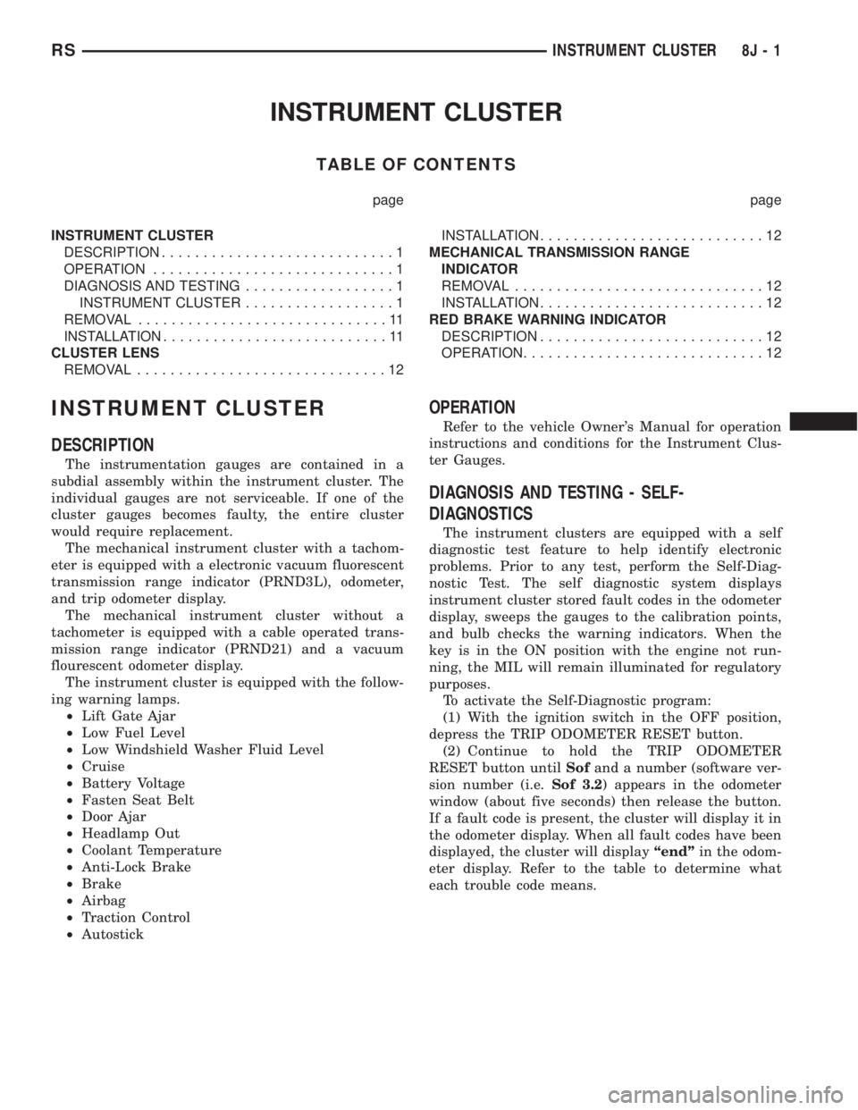
INSTRUMENT CLUSTER
TABLE OF CONTENTS
page page
INSTRUMENT CLUSTER
DESCRIPTION............................1
OPERATION.............................1
DIAGNOSIS AND TESTING..................1
INSTRUMENT CLUSTER..................1
REMOVAL..............................11
INSTALLATION...........................11
CLUSTER LENS
REMOVAL..............................12INSTALLATION...........................12
MECHANICAL TRANSMISSION RANGE
INDICATOR
REMOVAL..............................12
INSTALLATION...........................12
RED BRAKE WARNING INDICATOR
DESCRIPTION...........................12
OPERATION.............................12
INSTRUMENT CLUSTER
DESCRIPTION
The instrumentation gauges are contained in a
subdial assembly within the instrument cluster. The
individual gauges are not serviceable. If one of the
cluster gauges becomes faulty, the entire cluster
would require replacement.
The mechanical instrument cluster with a tachom-
eter is equipped with a electronic vacuum fluorescent
transmission range indicator (PRND3L), odometer,
and trip odometer display.
The mechanical instrument cluster without a
tachometer is equipped with a cable operated trans-
mission range indicator (PRND21) and a vacuum
flourescent odometer display.
The instrument cluster is equipped with the follow-
ing warning lamps.
²Lift Gate Ajar
²Low Fuel Level
²Low Windshield Washer Fluid Level
²Cruise
²Battery Voltage
²Fasten Seat Belt
²Door Ajar
²Headlamp Out
²Coolant Temperature
²Anti-Lock Brake
²Brake
²Airbag
²Traction Control
²Autostick
OPERATION
Refer to the vehicle Owner's Manual for operation
instructions and conditions for the Instrument Clus-
ter Gauges.
DIAGNOSIS AND TESTING - SELF-
DIAGNOSTICS
The instrument clusters are equipped with a self
diagnostic test feature to help identify electronic
problems. Prior to any test, perform the Self-Diag-
nostic Test. The self diagnostic system displays
instrument cluster stored fault codes in the odometer
display, sweeps the gauges to the calibration points,
and bulb checks the warning indicators. When the
key is in the ON position with the engine not run-
ning, the MIL will remain illuminated for regulatory
purposes.
To activate the Self-Diagnostic program:
(1) With the ignition switch in the OFF position,
depress the TRIP ODOMETER RESET button.
(2) Continue to hold the TRIP ODOMETER
RESET button untilSofand a number (software ver-
sion number (i.e.Sof 3.2) appears in the odometer
window (about five seconds) then release the button.
If a fault code is present, the cluster will display it in
the odometer display. When all fault codes have been
displayed, the cluster will displayªendºin the odom-
eter display. Refer to the table to determine what
each trouble code means.
RSINSTRUMENT CLUSTER8J-1
Page 2101 of 4284

Component Page
Torque Converter Clutch Solenoid........ 8Wa-31
Traction Control Switch................ 8Wa-35
Trailer Tow Connector................. 8Wa-54
Transmission Control Module........... 8Wa-31
Transmission Control Relay............. 8Wa-31
Transmission Range Sensor............. 8Wa-31
Turn Signal Lamps................... 8Wa-52
TXV Solenoid........................ 8Wa-42Component Page
Vehicle Speed Sensor.................. 8Wa-30
Vent Motors......................... 8Wa-60
Visor/Vanity Lamps................... 8Wa-44
Washer Fluid Level Switch............. 8Wa-53
Water In Fuel Sensor.................. 8Wa-30
Wheel Speed Sensors.................. 8Wa-35
Wiper Module........................ 8Wa-53
RG8W-02 COMPONENT INDEX8Wa-02-3
Page 2165 of 4284
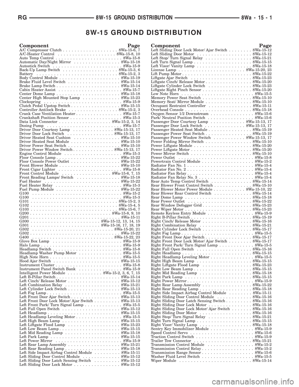
8W-15 GROUND DISTRIBUTION
Component PageA/C Compressor Clutch...................8Wa-15-6, 7
A/C-Heater Control....................8Wa-15-8, 10
Auto Temp Control.......................8Wa-15-8
Automatic Day/Night Mirror................8Wa-15-18
Autostick Switch........................8Wa-15-9
Back-Up Lamp Switch...................8Wa-15-3, 6
Battery............................8Wa-15-2, 3
Body Control Module.....................8Wa-15-19
Brake Fluid Level Switch..................8Wa-15-14
Brake Lamp Switch......................8Wa-15-14
Cabin Heater Assist......................8Wa-15-7
Center Dome Lamp......................8Wa-15-18
Center High Mounted Stop Lamp.............8Wa-15-23
Clockspring...........................8Wa-15-9
Clutch Pedal Upstop Switch.................8Wa-15-15
Controller Antilock Brake.................8Wa-15-2, 3
Crank Case Ventilation Heater................8Wa-15-7
Crankshaft Position Sensor..................8Wa-15-3
Data Link Connector..................8Wa-15-2, 3, 14
Dosing Pump..........................8Wa-15-7
Driver Door Courtesy Lamp..............8Wa-15-13, 17
Driver Door Lock Switch................8Wa-15-13, 17
Driver Heated Seat Cushion................8Wa-15-10
Driver Heated Seat Module.................8Wa-15-10
Driver Power Seat Switch..................8Wa-15-10
Driver Power Window Switch..............8Wa-15-13, 17
Engine Control Module....................8Wa-15-3
Floor Console Lamp......................8Wa-15-22
Floor Console Power Outlet.................8Wa-15-22
Front Blower Module.....................8Wa-15-10
Front Cigar Lighter......................8Wa-15-8
Front Control Module.................8Wa-15-6, 7, 15
Front Reading Lamps/ Switch...............8Wa-15-18
Fuel Heater..........................8Wa-15-22
Fuel Heater Relay.......................8Wa-15-3
Fuel Pump Module......................8Wa-15-22
G100...............................8Wa-15-2
G100...............................8Wa-15-3
G101..............................8Wa-15-2, 3
G102..............................8Wa-15-4, 5
G103..............................8Wa-15-6, 7
G200............................8Wa-15-8, 9, 10
G201...............................8Wa-15-11
G300........................8Wa-15-12, 13, 14, 15
G301........................8Wa-15-16, 17, 18, 19
G302............................8Wa-15-20, 21
G302...............................8Wa-15-22
G400............................8Wa-15-22, 23
Glove Box Lamp........................8Wa-15-9
Halo Lamp............................8Wa-15-9
Headlamp Switch........................8Wa-15-8
Headlamp Washer Pump Motor...............8Wa-15-5
High Note Horn.........................8Wa-15-5
Hood Ajar Switch.......................8Wa-15-15
Instrument Cluster.......................8Wa-15-8
Instrument Panel Switch Bank...............8Wa-15-9
Intelligent Power Module............8Wa-15-2, 3, 6, 7, 15
Left B-Pillar Switch......................8Wa-15-14
Left Cinch/ Release Motor..................8Wa-15-12
Left Combination Relay...................8Wa-15-21
Left Cylinder Lock Switch..................8Wa-15-13
Left Fog Lamp..........................8Wa-15-5
Left Front Door Ajar Switch.................8Wa-15-13
Left Front Door Lock Motor/ Ajar Switch.........8Wa-15-13
Left Front Park/ Turn Signal Lamp.............8Wa-15-5
Left Full Open Switch....................8Wa-15-12
Left Headlamp.........................8Wa-15-15
Left Headlamp Leveling Motor................8Wa-15-5
Left High Beam Lamp....................8Wa-15-15
Left Liftgate Flood Lamp..................8Wa-15-23
Left Low Beam Lamp.....................8Wa-15-15
Left Mid Reading Lamp...................8Wa-15-18
Left Park Lamp........................8Wa-15-15
Left Power Mirror.......................8Wa-15-9
Left Rear Lamp Assembly..................8Wa-15-21
Left Rear Reading Lamp...................8Wa-15-18
Left Side Impact Airbag Control Module.........8Wa-15-11
Left Sliding Door Control Module.............8Wa-15-12
Left Sliding Door Latch Sensing Switch.........8Wa-15-12
Left Sliding Door Lock Motor................8Wa-15-12Component PageLeft Sliding Door Lock Motor/ Ajar Switch........8Wa-15-12
Left Sliding Door Motor...................8Wa-15-12
Left Stop/ Turn Signal Relay................8Wa-15-21
Left Turn Signal Lamp....................8Wa-15-15
Left Visor/ Vanity Lamp...................8Wa-15-18
License Lamp.......................8Wa-15-20, 23
Lift Pump Motor........................8Wa-15-22
Liftgate Ajar Switch.....................8Wa-15-23
Liftgate Cinch/ Release Motor................8Wa-15-20
Liftgate Cylinder Lock Switch...............8Wa-15-23
Liftgate Right Pinch Sensor.................8Wa-15-20
Low Note Horn.........................8Wa-15-5
Memory Power Seat Switch.................8Wa-15-10
Memory Seat/ Mirror Module................8Wa-15-10
Occupant Restraint Controller...............8Wa-15-11
Overhead Console.......................8Wa-15-18
Oxygen Sensor 1/2 Downstream...............8Wa-15-6
Park/ Neutral Position Switch................8Wa-15-6
Passenger Door Courtesy Lamp............8Wa-15-13, 17
Passenger Door Lock Switch..............8Wa-15-13, 17
Passenger Heated Seat Module...............8Wa-15-19
Passenger Power Seat Switch................8Wa-15-19
Passenger Power Window Switch...........8Wa-15-13, 17
Power Folding Mirror Switch................8Wa-15-10
Power Liftgate Module....................8Wa-15-20
Power Liftgate Motor.....................8Wa-15-20
Power Mirror Switch.....................8Wa-15-10
Power Outlet..........................8Wa-15-8
Powertrain Control Module..................8Wa-15-2
Radiator Fan No. 1.......................8Wa-15-4
Radiator Fan No. 2.......................8Wa-15-4
Radiator Fan Relay.......................8Wa-15-4
Radiator Fan Relay No. 3...................8Wa-15-4
Rear Auto Temp Control Switch..............8Wa-15-14
Rear Blower Front Control Switch.............8Wa-15-10
Rear Blower Motor Power Module...........8Wa-15-10, 22
Rear Blower Rear Control Switch.............8Wa-15-14
Rear Dome Lamp.......................8Wa-15-18
Rear Power Outlet......................8Wa-15-22
Rear Window Defogger Grid.................8Wa-15-23
Rear Wiper Motor.......................8Wa-15-23
Remote Keyless Entry Module................8Wa-15-9
Right B-Pillar Switch.....................8Wa-15-19
Right Cinch/ Release Motor.................8Wa-15-16
Right Combination Relay..................8Wa-15-21
Right Cylinder Lock Switch.................8Wa-15-17
Right Fog Lamp.........................8Wa-15-5
Right Front Door Ajar Switch................8Wa-15-17
Right Front Door Lock Motor/ Ajar Switch........8Wa-15-17
Right Front Park/ Turn Signal Lamp............8Wa-15-5
Right Full Open Switch...................8Wa-15-16
Right Headlamp........................8Wa-15-15
Right Headlamp Leveling Motor...............8Wa-15-5
Right High Beam Lamp...................8Wa-15-15
Right Liftgate Flood Lamp.................8Wa-15-23
Right Low Beam Lamp....................8Wa-15-15
Right Mid Reading Lamp..................8Wa-15-18
Right Park Lamp.......................8Wa-15-15
Right Power Mirror.......................8Wa-15-9
Right Rear Lamp Assembly.................8Wa-15-22
Right Rear Reading Lamp..................8Wa-15-18
Right Side Impact Airbag Control Module........8Wa-15-11
Right Sliding Door Control Module............8Wa-15-16
Right Sliding Door Latch Sensing Switch.........8Wa-15-16
Right Sliding Door Lock Motor...............8Wa-15-16
Right Sliding Door Lock Motor/ Ajar Switch.......8Wa-15-16
Right Sliding Door Motor..................8Wa-15-16
Right Stop/ Turn Signal Relay...............8Wa-15-21
Right Turn Signal Lamp...................8Wa-15-15
Right Visor/ Vanity Lamp..................8Wa-15-18
Sentry Key Immobilizer Module...............8Wa-15-9
Speed Control Servo......................8Wa-15-6
Traction Control Switch....................8Wa-15-9
Trailer Tow Connector....................8Wa-15-21
Transmission Control Module................8Wa-15-2
Transmission Control Relay..................8Wa-15-2
Transmission Range Sensor..................8Wa-15-6
Washer Fluid Level Switch..................8Wa-15-5
Wiper Module.........................8Wa-15-14
RG8W-15 GROUND DISTRIBUTION8Wa-15-1