2001 CHRYSLER VOYAGER check engine
[x] Cancel search: check enginePage 1658 of 4284
STANDARD PROCEDURE - BRAKE FLUID
LEVEL CHECKING
Check master cylinder reservoir fluid level a mini-
mum of twice annually.
Fluid reservoirs are marked with the words FULL
and ADD to indicate proper brake fluid fill level of
the master cylinder.
If necessary, add brake fluid to bring the level to
the bottom of the FULL mark on the side of the mas-
ter cylinder fluid reservoir.
Use only Mopartbrake fluid or equivalent from a
sealed container. Brake fluid must conform to DOT 3
specifications (DOT 4 or DOT 4+ are acceptable).
DO NOTuse brake fluid with a lower boiling
point, as brake failure could result during prolonged
hard braking.
Use only brake fluid that was stored in a tightly-
sealed container.
DO NOTuse petroleum-based fluid because seal
damage will result. Petroleum based fluids would be
items such as engine oil, transmission fluid, power
steering fluid etc.
SPECIFICATIONS
BRAKE FLUID
The brake fluid used in this vehicle must conform
to DOT 3 specifications (DOT 4 and DOT 4+ are
acceptable) and SAE J1703 standards. No other type
of brake fluid is recommended or approved for usage
in the vehicle brake system. Use only MopartBrake
Fluid or equivalent from a tightly sealed container.
CAUTION: Never use reclaimed brake fluid or fluid
from an container which has been left open. An
open container of brake fluid will absorb moisture
from the air and contaminate the fluid.
CAUTION: Never use any type of a petroleum-based
fluid in the brake hydraulic system. Use of such
type fluids will result in seal damage of the vehicle
brake hydraulic system causing a failure of the
vehicle brake system. Petroleum based fluids would
be items such as engine oil, transmission fluid,
power steering fluid, etc.
JUNCTION BLOCK
DESCRIPTION - NON-ABS JUNCTION BLOCK
A junction block is used on vehicles that are not
equipped with antilock brakes (ABS). The junction
block mounts in the same location as the integrated
control unit (ICU) does on vehicles equipped withABS. This allows for use of the same brake tube con-
figuration on all vehicles. The junction block is
located on the driver's side of the front suspension
cradle/crossmember below the master cylinder (Fig.
46).
It has six threaded ports to which the brake tubes
connect. Two are for the primary and secondary
brake tubes coming from the master cylinder. The
remaining four are for the chassis brake tubes going
to each brake assembly.
OPERATION - NON-ABS JUNCTION BLOCK
The junction block distributes the brake fluid com-
ing from the master cylinder primary and secondary
ports to the four chassis brake tubes leading to the
brakes at each wheel. Since the junction block
mounts in the same location as the ABS integrated
control unit (ICU), it allows for the common use of
brake tubes going to the brakes whether the vehicle
is equipped with or without ABS.
NOTE: Although the brake tubes coming from the
master cylinder to the junction block or ABS ICU
may appear to be the same, they are not. They are
unique to each brake system application.
REMOVAL - NON-ABS JUNCTION BLOCK
(1) Using a brake pedal depressor, move and lock
the brake pedal to a position past its first 1 inch of
travel. This will prevent brake fluid from draining
out of the master cylinder when the brake tubes are
removed from the junction block.
(2) Disconnect the battery negative cable.
(3) If the vehicle is equipped with speed control,
perform the following:
(a) Disconnect the battery positive cable.
(b) Remove the battery (Refer to 8 - ELECTRI-
CAL/BATTERY SYSTEM/BATTERY - REMOVAL).
(c) Disconnect the vacuum hose connector at the
tank built into the battery tray.
(d) Remove the screw securing the coolant filler
neck to the battery tray.
(e) Remove the battery tray (Refer to 8 - ELEC-
TRICAL/BATTERY SYSTEM/TRAY - REMOVAL).
(f) Remove the fasteners and move the speed
control servo off to the side, out of the way.
CAUTION: Before removing the brake tubes from
the junction block, the junction block and the brake
tubes must be thoroughly cleaned. This is required
to prevent contamination from entering the brake
hydraulic system.
5 - 32 BRAKES - BASERS
FLUID (Continued)
Page 1663 of 4284
POWER BRAKE BOOSTER
DESCRIPTION
The power brake booster mounts on the engine
compartment side of the dash panel. It is connected
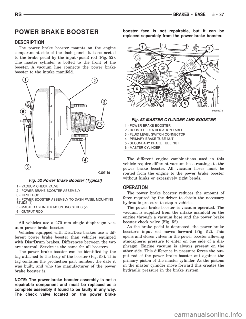
to the brake pedal by the input (push) rod (Fig. 52).
The master cylinder is bolted to the front of the
booster. A vacuum line connects the power brake
booster to the intake manifold.
All vehicles use a 270 mm single diaphragm vac-
uum power brake booster.
Vehicles equipped with Disc/Disc brakes use a dif-
ferent power brake booster than vehicles equipped
with Disc/Drum brakes. Differences between the two
are internal. Service is the same for all boosters.
The power brake booster can be identified by the
tag attached to the body of the booster (Fig. 53). This
tag contains the production part number, the date it
was built, and who the manufacturer of the power
brake booster is.
NOTE: The power brake booster assembly is not a
repairable component and must be replaced as a
complete assembly if found to be faulty in any way.
The check valve located on the power brakebooster face is not repairable, but it can be
replaced separately from the power brake booster.
The different engine combinations used in this
vehicle require different vacuum hose routings to the
power brake booster. All vacuum hoses must be
routed from the engine to the power brake booster
without kinks or excessively tight bends.
OPERATION
The power brake booster reduces the amount of
force required by the driver to obtain the necessary
hydraulic pressure to stop a vehicle.
The power brake booster is vacuum operated. The
vacuum is supplied from the intake manifold on the
engine through a vacuum hose and the power brake
booster check valve (Fig. 52).
As the brake pedal is depressed, the power brake
booster's input rod moves forward (Fig. 52). This
opens and closes valves in the power booster allowing
atmospheric pressure to enter on one side of a dia-
phragm. Engine vacuum is always present on the
other side. This difference in pressure forces the out-
put rod of the power brake booster out against the
primary piston of the master cylinder. As the pistons
in the master cylinder move forward this creates the
hydraulic pressure in the brake system.
Fig. 52 Power Brake Booster (Typical)
1 - VACUUM CHECK VALVE
2 - POWER BRAKE BOOSTER ASSEMBLY
3 - INPUT ROD
4 - POWER BOOSTER ASSEMBLY TO DASH PANEL MOUNTING
STUDS (4)
5 - MASTER CYLINDER MOUNTING STUDS (2)
6 - OUTPUT ROD
Fig. 53 MASTER CYLINDER AND BOOSTER
1 - POWER BRAKE BOOSTER
2 - BOOSTER IDENTIFICATION LABEL
3 - FLUID LEVEL SWITCH CONNECTOR
4 - PRIMARY BRAKE TUBE NUT
5 - SECONDARY BRAKE TUBE NUT
6 - MASTER CYLINDER
RSBRAKES - BASE5-37
Page 1664 of 4284
DIAGNOSIS AND TESTING - POWER BRAKE
BOOSTER
BASIC TEST
(1) With engine off, depress and release the brake
pedal several times to purge all vacuum from the
power brake booster.
(2) Depress and hold the pedal with light effort (15
to 25 lbs. pressure), then start the engine.
The pedal should fall slightly, then hold. Less effort
should be needed to apply the pedal at this time. If
the pedal fell as indicated, perform the VACUUM
LEAK TEST listed after the BASIC TEST. If the
pedal did not fall, continue on with this BASIC TEST.
(3) Disconnect the vacuum hose on the vacuum
check valve, then place a vacuum gauge in line
between the vacuum hose and the valve.
(4) Start the engine.
(5) When the engine is at warm operating temper-
ature, allow it to idle and check the vacuum at the
gauge.
If the vacuum supply is 12 inches Hg (40.5 kPa) or
more, the power brake booster is defective and must
be replaced. If the vacuum supply is below 12 inches
Hg, continue on with this BASIC TEST.
(6) Shut off the engine.
(7) Connect the vacuum gauge to the vacuum ref-
erence port on the engine intake manifold.
(8) Start the engine and observe the vacuum
gauge.
If the vacuum is still low, check the engine tune
and repair as necessary. If the vacuum is above 12
inches Hg, the hose or check valve to the booster has
a restriction or leak.
Once an adequate vacuum supply is obtained,
repeat the BASIC TEST.
VACUUM LEAK TEST
(1) Disconnect the vacuum hose on the vacuum
check valve, then place a vacuum gauge in line
between the vacuum hose and the valve.
(2) Start the engine.
(3) Allow the engine to warm up to normal operat-
ing temperature and engine idle.
(4) Using vacuum line pliers, close off the vacuum
supply hose near the booster, but before the vacuum
gauge, then observe the vacuum gauge.
If the vacuum drop exceeds 1.0 inch Hg (3.3 kPa)
in one minute, repeat the above steps to confirm the
reading. The vacuum loss should be less than 1.0
inch Hg in one minute time span. If the loss is more
than 1.0 inch Hg, replace the power brake booster. If
it is not, continue on with this test.
(5) Remove the pliers from the hose temporarily.
(6) Apply light effort (approximately 15 lbs. of
force) to the brake pedal and hold the pedal steady.Do not move the pedal once the pressure is applied
or the test results may vary.
(7) Have an assistant reattach the vacuum line
pliers to the vacuum supply hose.
(8) Allow 5 seconds for stabilization, then observe
the vacuum gauge.
If the vacuum drop exceeds 3.0 inches Hg (10 kPa)
in 15 seconds, repeat the above steps to confirm the
reading. The vacuum loss should be less than 3.0
inches Hg in 15 seconds time span. If the loss is
more than 3.0 inches Hg, replace the power brake
booster. If it is not, the booster is not defective.
(9) Remove the pliers and vacuum gauge.
REMOVAL - POWER BRAKE BOOSTER
CAUTION: Reserve vacuum in power brake booster
must be pumped down (removed) before removing
master cylinder from booster. This is necessary to
prevent booster from sucking in any contamination
as master cylinder is removed. This can be done
simply by pumping the brake pedal, with the vehi-
cle's engine not running, until a firm feeling brake
pedal is achieved.
(1) With engine not running, pump the brake
pedal until a firm pedal is achieved (4-5 strokes).
(2) Remove negative battery cable terminal from
battery.
(3) Remove positive battery cable terminal from
battery.
(4) Remove battery thermal guard shield.
(5) Remove battery clamp, nut and battery from
the battery tray.
(6) Remove screw securing engine coolant filler
tube to battery tray.
(7) If the vehicle is equipped with speed control,
disconnect the vacuum hose at the vacuum tank built
into the battery tray.
(8) Remove the two nuts and one bolt securing bat-
tery tray in place. Remove battery tray.
(9) If vehicle is equipped with speed control:
(a) Disconnect wiring harness connector from
the speed control servo.
(b) Remove the two servo mounting nuts.
(c) Lay speed control servo off to the side, out of
the way.
(10) Remove the wiper module (unit). (Refer to 8 -
ELECTRICAL/WIPERS/WASHERS/WIPER MOD-
ULE - REMOVAL)
(11) Disconnect wiring harness connector from
brake fluid level switch in master cylinder fluid res-
ervoir (Fig. 54).
5 - 38 BRAKES - BASERS
POWER BRAKE BOOSTER (Continued)
Page 1666 of 4284

(19) Rotate screwdriver enough to allow retaining
clip center tang to pass over end of brake pedal pin.
Then pull retaining clip off brake pedal pin.Discard
retaining clip. It is not to be reused. Replace
only with a new retaining clip when assem-
bling.
(20) Slide booster input rod off pedal pin.
(21) Remove the four nuts attaching power brake
booster to dash panel (Fig. 57).
(22) Slide power brake booster forward and remove
through engine compartment (Fig. 58).
CAUTION: Do not attempt to disassemble the power
brake vacuum booster it is serviced ONLY as a
complete assembly.INSTALLATION - POWER BRAKE BOOSTER
(1) Position power brake booster on dash panel
using the reverse procedure of its removal (Fig. 58).
It may be necessary to push in on booster input rod
as it is guided through the dash panel.
(2) Install the four nuts mounting the booster to
the dash panel (Fig. 57). Tighten the mounting nuts
to a torque of 29 N´m (250 in. lbs.).
(3) Using lubriplate, or equivalent, coat the sur-
face of the brake pedal pin where it contacts the
booster input rod.
CAUTION: When installing the brake pedal pin on
the power brake booster input rod, do not re-use
the old retaining clip.
(4) Install booster input rod on brake pedal pin
and install a NEW retaining clip (Fig. 59).
CAUTION: Do not reuse the original brake lamp
switch. The switch can only be adjusted once. That
is during initial installation of the switch. If the
switch is not adjusted properly or has been
removed for some service, a new switch must be
installed and adjusted.
(5) Remove and replace the brake lamp switch
with a NEW switch. (Refer to 8 - ELECTRICAL/
LAMPS/LIGHTING - EXTERIOR/BRAKE LAMP
SWITCH - REMOVAL), (Refer to 8 - ELECTRICAL/
LAMPS/LIGHTING - EXTERIOR/BRAKE LAMP
SWITCH - INSTALLATION)
(6) Install the silencer panel below the steering
column.
(7) Connect vacuum hose to check valve on power
brake booster.
Fig. 57 BOOSTER MOUNTING
1 - DASH BRACKET
2 - POWER BRAKE BOOSTER
3 - BRAKE PEDAL ASSEMBLY
Fig. 58 BOOSTER REMOVAL/INSTALLATION
Fig. 59 Retaining Pin Installed On Brake Pedal Pin
1 - BRAKE PEDAL
2 - RETAINING CLIP
3 - BOOSTER INPUT ROD
5 - 40 BRAKES - BASERS
POWER BRAKE BOOSTER (Continued)
Page 1709 of 4284
(6) If the vehicle is equipped with speed control,
disconnect the vacuum hose at the vacuum tank built
into the battery tray.
(7) Remove the two nuts and one bolt securing bat-
tery tray in place. Remove battery tray.
(8) If vehicle is equipped with speed control:
(a) Disconnect wiring harness connector from
the speed control servo.
(b) Remove the two servo mounting nuts.
(c) Lay speed control servo off to the side, out of
the way.
(9) If the vehicle is equipped with the 2.5L diesel
engine, remove the coolant recovery pressure con-
tainer and bracket. (Refer to 7 - COOLING/ENGINE/
COOLANT RECOVERY PRESS CONTAINER -
REMOVAL)
(10) Disconnect wiring harness connector from
brake fluid level switch in master cylinder fluid res-
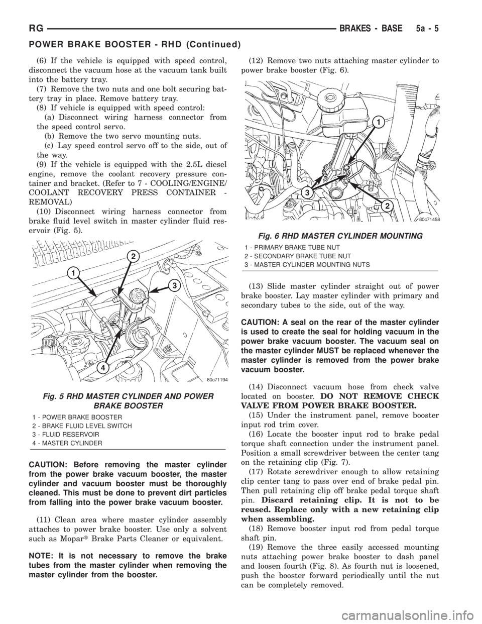
ervoir (Fig. 5).
CAUTION: Before removing the master cylinder
from the power brake vacuum booster, the master
cylinder and vacuum booster must be thoroughly
cleaned. This must be done to prevent dirt particles
from falling into the power brake vacuum booster.
(11) Clean area where master cylinder assembly
attaches to power brake booster. Use only a solvent
such as MopartBrake Parts Cleaner or equivalent.
NOTE: It is not necessary to remove the brake
tubes from the master cylinder when removing the
master cylinder from the booster.(12) Remove two nuts attaching master cylinder to
power brake booster (Fig. 6).
(13) Slide master cylinder straight out of power
brake booster. Lay master cylinder with primary and
secondary tubes to the side, out of the way.
CAUTION: A seal on the rear of the master cylinder
is used to create the seal for holding vacuum in the
power brake vacuum booster. The vacuum seal on
the master cylinder MUST be replaced whenever the
master cylinder is removed from the power brake
vacuum booster.
(14) Disconnect vacuum hose from check valve
located on booster.DO NOT REMOVE CHECK
VALVE FROM POWER BRAKE BOOSTER.
(15) Under the instrument panel, remove booster
input rod trim cover.
(16) Locate the booster input rod to brake pedal
torque shaft connection under the instrument panel.
Position a small screwdriver between the center tang
on the retaining clip (Fig. 7).
(17) Rotate screwdriver enough to allow retaining
clip center tang to pass over end of brake pedal pin.
Then pull retaining clip off brake pedal torque shaft
pin.Discard retaining clip. It is not to be
reused. Replace only with a new retaining clip
when assembling.
(18) Remove booster input rod from pedal torque
shaft pin.
(19) Remove the three easily accessed mounting
nuts attaching power brake booster to dash panel
and loosen fourth (Fig. 8). As fourth nut is loosened,
push the booster forward periodically until the nut
can be completely removed.
Fig. 5 RHD MASTER CYLINDER AND POWER
BRAKE BOOSTER
1 - POWER BRAKE BOOSTER
2 - BRAKE FLUID LEVEL SWITCH
3 - FLUID RESERVOIR
4 - MASTER CYLINDER
Fig. 6 RHD MASTER CYLINDER MOUNTING
1 - PRIMARY BRAKE TUBE NUT
2 - SECONDARY BRAKE TUBE NUT
3 - MASTER CYLINDER MOUNTING NUTS
RGBRAKES - BASE5a-5
POWER BRAKE BOOSTER - RHD (Continued)
Page 1710 of 4284
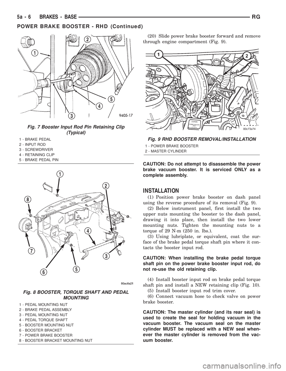
(20) Slide power brake booster forward and remove
through engine compartment (Fig. 9).
CAUTION: Do not attempt to disassemble the power
brake vacuum booster. It is serviced ONLY as a
complete assembly.
INSTALLATION
(1) Position power brake booster on dash panel
using the reverse procedure of its removal (Fig. 9).
(2) Below instrument panel, first install the two
upper nuts mounting the booster to the dash panel,
drawing it into place, then install the two lower
mounting nuts. Tighten the mounting nuts to a
torque of 29 N´m (250 in. lbs.).
(3) Using lubriplate, or equivalent, coat the sur-
face of the brake pedal torque shaft pin where it con-
tacts the booster input rod.
CAUTION: When installing the brake pedal torque
shaft pin on the power brake booster input rod, do
not re-use the old retaining clip.
(4) Install booster input rod on brake pedal torque
shaft pin and install a NEW retaining clip (Fig. 10).
(5) Install booster input rod trim cover.
(6) Connect vacuum hose to check valve on power
brake booster.
CAUTION: The master cylinder (and its rear seal) is
used to create the seal for holding vacuum in the
vacuum booster. The vacuum seal on the master
cylinder MUST be replaced with a NEW seal when-
ever the master cylinder is removed from the vac-
uum booster.
Fig. 7 Booster Input Rod Pin Retaining Clip
(Typical)
1 - BRAKE PEDAL
2 - INPUT ROD
3 - SCREWDRIVER
4 - RETAINING CLIP
5 - BRAKE PEDAL PIN
Fig. 8 BOOSTER, TORQUE SHAFT AND PEDAL
MOUNTING
1 - PEDAL MOUNTING NUT
2 - BRAKE PEDAL ASSEMBLY
3 - PEDAL MOUNTING NUT
4 - PEDAL TORQUE SHAFT
5 - BOOSTER MOUNTING NUT
6 - BOOSTER BRACKET
7 - POWER BRAKE BOOSTER
8 - BOOSTER BRACKET MOUNTING NUT
Fig. 9 RHD BOOSTER REMOVAL/INSTALLATION
1 - POWER BRAKE BOOSTER
2 - MASTER CYLINDER
5a - 6 BRAKES - BASERG
POWER BRAKE BOOSTER - RHD (Continued)
Page 1722 of 4284
DIAGNOSIS AND TESTING - CLUTCH SYSTEM
Clutch problem diagnosis will generally require a
road test to determine the type of fault. Component
inspection will then determine the problem after road
testing.
Drive the vehicle at normal speeds during road
test. Shift the transaxle through all gear ranges and
observe clutch action. If chatter, grab, slip, or
improper release is experienced, remove and inspect
the clutch components. If the problem is noise or
hard shifting, further diagnosis may be needed. The
transaxle or other driveline components may actually
be at fault.
SERVICE DIAGNOSIS - CLUTCH GRAB/CHATTER
CONDITION POSSIBLE CAUSES CORRECTION
CLUTCH DISC FACING
COVERED WITH OIL OR
GREASEOil leak at engine rear main or
transaxle input shaft seal.Correct leak and replace modular clutch
assembly (2.4L Gas) or clutch cover and
disc (2.5L TD).
Too much grease applied to splines
of disc and input shaft.Apply lighter coating of grease to splines.
NO FAULT FOUND WITH
CLUTCH
COMPONENTSProblem actually related to
suspension or driveline component.Further diagnosis required. Check
engine/transmission mounts, suspension
attaching parts and other driveline
components as needed.
Engine related problems. Check EFI and ignition systems.
PARTIAL ENGAGEMENT
OF CLUTCH DISCClutch cover, spring, or release
fingers bent, distorted (rough
handling, improper assembly).Replace modular clutch assembly (2.4L
Gas) or clutch cover and disc (2.5L TD).
Clutch disc damaged or distorted. Replace modular clutch assembly (2.4L
Gas) or clutch cover and disc (2.5L TD).
Clutch misalignment. Verify modular clutch pilot plate alignment
to crankshaft. Replace the modular clutch
assembly (2.4L Gas) or clutch cover and
disc (2.5L TD) if the pilot plate is loose or
bent.
Improper transaxle-to-engine
installation.Verify transaxle is properly installed to
engine.
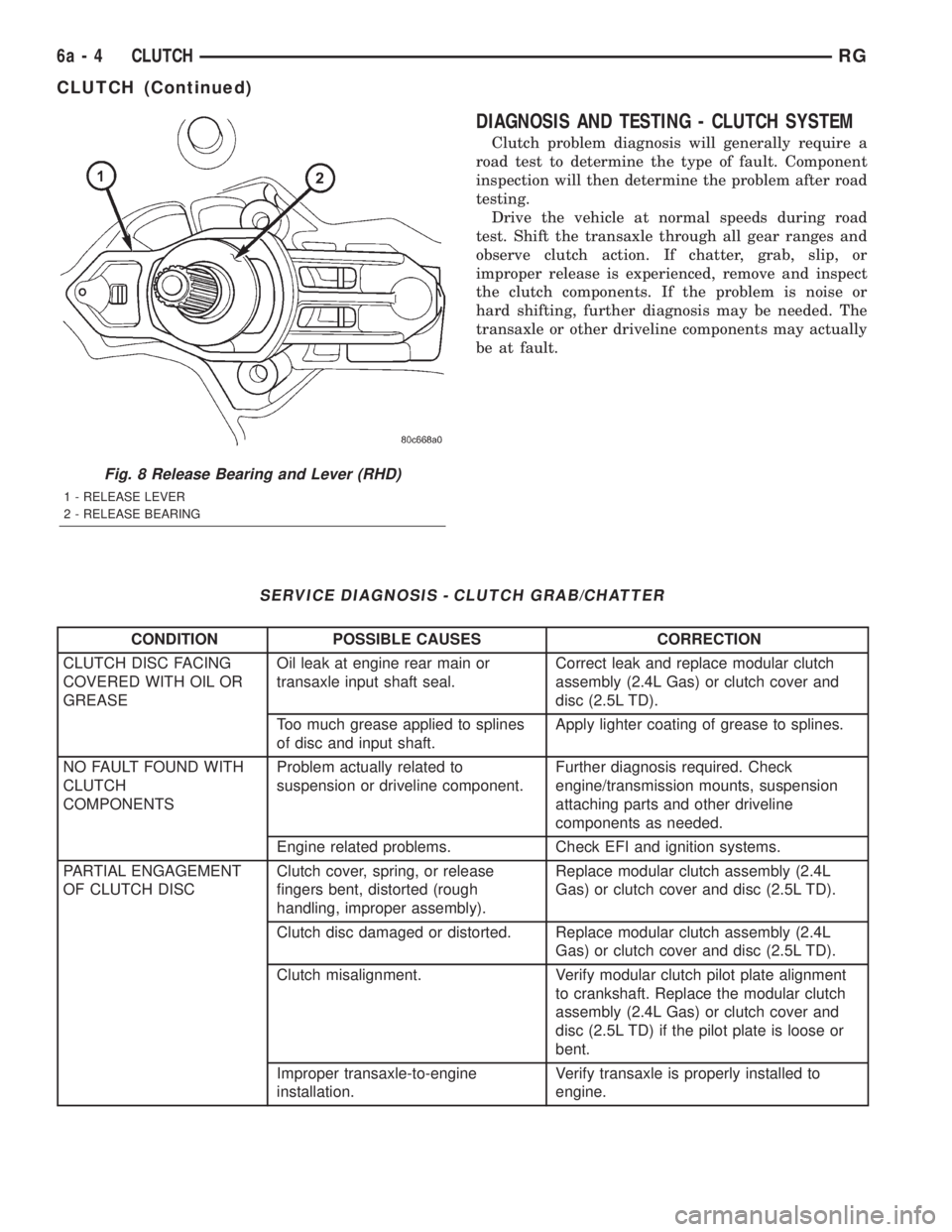
Fig. 8 Release Bearing and Lever (RHD)
1 - RELEASE LEVER
2 - RELEASE BEARING
6a - 4 CLUTCHRG
CLUTCH (Continued)
Page 1725 of 4284
DIAGNOSIS AND TESTING - DRIVE PLATE
MISALIGNMENT
Common causes of misalignment are:
²Heat warping
²Mounting drive plate on a dirty crankshaft
flange
²Incorrect bolt tightening
²Improper seating on the crankshaft shoulder
²Loose crankshaft bolts
Clean the crankshaft flange before mounting the
drive plate. Dirt and grease on the flange surface
may misalign the flywheel, causing excessive runout.
Use new bolts when mounting drive plate to crank-
shaft. Tighten drive plate bolts to specified torque
only. Over-tightening can distort the drive plate hub
causing excessive runout.
DIAGNOSIS AND TESTING - CLUTCH COVER
AND DISC RUNOUT
Check condition of the clutch cover before installa-
tion. A warped cover or diaphragm spring will cause
grab and/or incomplete release or engagement. Use
care when handling the clutch assembly. Impact can
distort the cover, diaphragm spring, and release fin-
gers.
DIAGNOSIS AND TESTING - CLUTCH CHATTER
COMPLAINTS
For all clutch chatter complaints, perform the fol-
lowing:
(1) Check for loose, misaligned, or broken engine
and transmission mounts. If present, they should be
corrected at this time. Test vehicle for chatter. If
chatter is gone, there is no need to go any further.
(2) If chatter persists, check hydraulic clutch
release system is functioning properly.
(3) Check for loose connections in drivetrain. Cor-
rect any problems and determine if clutch chatter
complaints have been satisfied. If not:
(a) Remove transaxle.
(b) Check to see if the release bearing is sticky
or binding. Replace bearing, if needed.
(c) Check linkage for excessive wear on the pivot
stud and fork fingers. Replace all worn parts.
(d) Check clutch assembly for contamination
(dirt, oil). Replace clutch assembly, if required.
(e) Check to see if the clutch disc hub splines
are damaged. Replace with new clutch assembly, if
necessary.
(f) Check input shaft splines for damage.
Replace, if necessary.
(g) Check for uneven wear on clutch fingers.
(h) Check for broken clutch cover diaphragm
spring fingers. Replace with new clutch assembly,
if necessary.
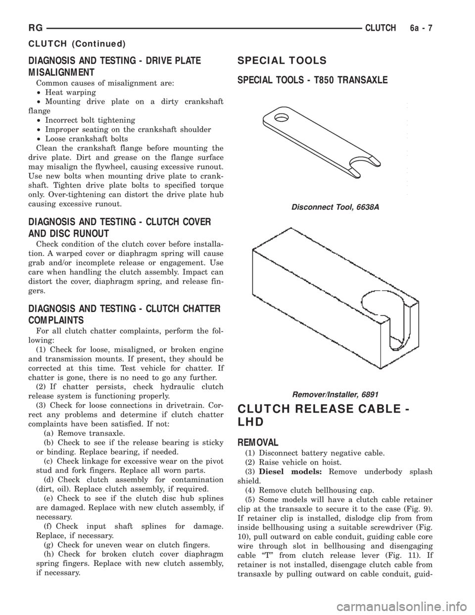
SPECIAL TOOLS
SPECIAL TOOLS - T850 TRANSAXLE
CLUTCH RELEASE CABLE -
LHD
REMOVAL
(1) Disconnect battery negative cable.
(2) Raise vehicle on hoist.
(3)Diesel models:Remove underbody splash
shield.
(4) Remove clutch bellhousing cap.
(5) Some models will have a clutch cable retainer
clip at the transaxle to secure it to the case (Fig. 9).
If retainer clip is installed, dislodge clip from from
inside bellhousing using a suitable screwdriver (Fig.
10), pull outward on cable conduit, guiding cable core
wire through slot in bellhousing and disengaging
cable ªTº from clutch release lever (Fig. 11). If
retainer is not installed, disengage clutch cable from
transaxle by pulling outward on cable conduit, guid-
Disconnect Tool, 6638A
Remover/Installer, 6891
RGCLUTCH6a-7
CLUTCH (Continued)