Page 4208 of 4770
 Dispose of the front passenger airbag")
W03619
AB0163
Wire Harness
Diameter
Stripped Wire Harness Section
± SUPPLEMENTAL RESTRAINT SYSTEMFRONT PASSENGER AIRBAG ASSEMBLY
RS±33
2178 Author�: Date�:
(e) Dispose of the front passenger airbag assembly.
CAUTION:
�The front passenger airbag assembly is very hot
when the airbag is deployed, so leave it alone for at
least 30 minutes after deployment.
�Use gloves and safety glasses when handling a front
passenger airbag assembly with deployed airbag.
�Always wash your hands with water after completing
the operation.
�Do not apply water, etc. to a front passenger airbag
assembly with deployed airbag.
(1) When scrapping a vehicle, deploy the airbag and
scrap the vehicle with the front passenger airbag
assembly still installed.
(2) When moving a vehicle for scrapping which has a
front passenger airbag assembly with deployed air-
bag, use gloves and safety glasses.
2. DEPLOYMENT WHEN DISPOSING OF FRONT PAS-
SENGER AIRBAG ASSEMBLY ONLY
NOTICE:
�When disposing of the front passenger airbag assem-
bly only, never use the customer's vehicle to deploy
the airbag.
�Be sure to follow the procedure given below when de-
ploying the airbag.
HINT:
Have a battery ready as the power source to deploy the airbag.
(a) Remove the front passenger airbag assembly.
(See page RS±28)
CAUTION:
�When removing the front passenger airbag assembly,
work must be started 90 seconds after the ignition
switch is turned to the ºLOCKº position and the nega-
tive (±) terminal cable is disconnected from the bat-
tery.
�Store the front passenger airbag assembly with the
airbag deployment side facing upward.
(b) Using a service±purpose wire harness for the vehicle, tie
down the front passenger airbag assembly to the tire.
Wire harness: Stripped wire harness section
1.25 mm
2
or more (0.0019 in.2 or more)
Page 4215 of 4770

2185 Author�: Date�:
REMOVAL
NOTICE:
�If the wiring connector of the SRS is disconnected
and the ignition")
RS0EU±01
H02270
H02259
RS±40
± SUPPLEMENTAL RESTRAINT SYSTEMSIDE AIRBAG ASSEMBLY (TMC Made)
2185 Author�: Date�:
REMOVAL
NOTICE:
�If the wiring connector of the SRS is disconnected
and the ignition switch is in ON or ACC position, DTCs
will be recorded.
�Never use the airbag parts from another vehicle.
When replacing parts, replace them with new parts.
1. REMOVE FRONT SEAT
(a) Remove the 2 seat track covers and 4 bolts.
(b) Power adjuster type:
Disconnect the power seat and side airbag connectors.
(c) Manual adjuster type:
Disconnect the side airbag connector.
NOTICE:
When handling the airbag connector, take care not to dam-
age the airbag wire harness.
(d) Remove the front seat.
NOTICE:
Be careful not to damage the body.
2. REMOVE FRONT SEAT CUSHION LOWER SHIELD
3. Manual adjuster type:
REMOVE RELEASE HANDLE
4. Manual adjuster type:
REMOVE VERTICAL ADJUSTER KNOB
5. Power adjuster type:
DISCONNECT CONNECTOR
Disconnect the connector from the power seat switch.
6. REMOVE FRONT SEAT CUSHION SHIELD
7. REMOVE FRONT SEAT CUSHION INNER SHIELD
8. REMOVE HEADREST
9. REMOVE HEADREST SUPPORT
10. REMOVE SEATBACK ASSEMBLY
(a) Remove the 4 bolts.
(b) Remove the hog rings.
(c) Remove the seatback assembly.
Page 4227 of 4770

2197 Author�: Date�:
REMOVAL
NOTICE:
�If the wiring connector of the SRS is disconnected
and the ignitio")
RS0EW±01
H02270
H02259
RS±52
± SUPPLEMENTAL RESTRAINT SYSTEMSIDE AIRBAG ASSEMBLY (TMMK Made)
2197 Author�: Date�:
REMOVAL
NOTICE:
�If the wiring connector of the SRS is disconnected
and the ignition switch is at ON or ACC position, DTCs
will be recorded.
�Never use the airbag parts from another vehicle.
When replacing parts, replace them with new parts.
1. REMOVE FRONT SEAT
(a) Remove the 2 seat track covers and 4 bolts.
(b) Power adjuster type:
Disconnect the power seat and side airbag connectors.
(c) Manual adjuster type:
Disconnect the side airbag connector.
NOTICE:
When handling the airbag connector, take care not to dam-
age the airbag wire harness.
(d) Remove the front seat.
NOTICE:
Be careful not to damage the body.
2. REMOVE FRONT SEAT CUSHION LOWER SHIELD
3. Manual adjuster type:
REMOVE RELEASE HANDLE
4. Manual adjuster type:
REMOVE VERTICAL ADJUSTER KNOB
5. Power adjuster type:
DISCONNECT CONNECTOR
Disconnect the connector from the power seat switch.
6. REMOVE FRONT SEAT CUSHION SHIELD
7. REMOVE SEATBACK ASSEMBLY
(a) Remove the 4 bolts.
(b) Remove the hog rings.
(c) Disconnect the side airbag connector of the side airbag
assembly side.
Page 4239 of 4770
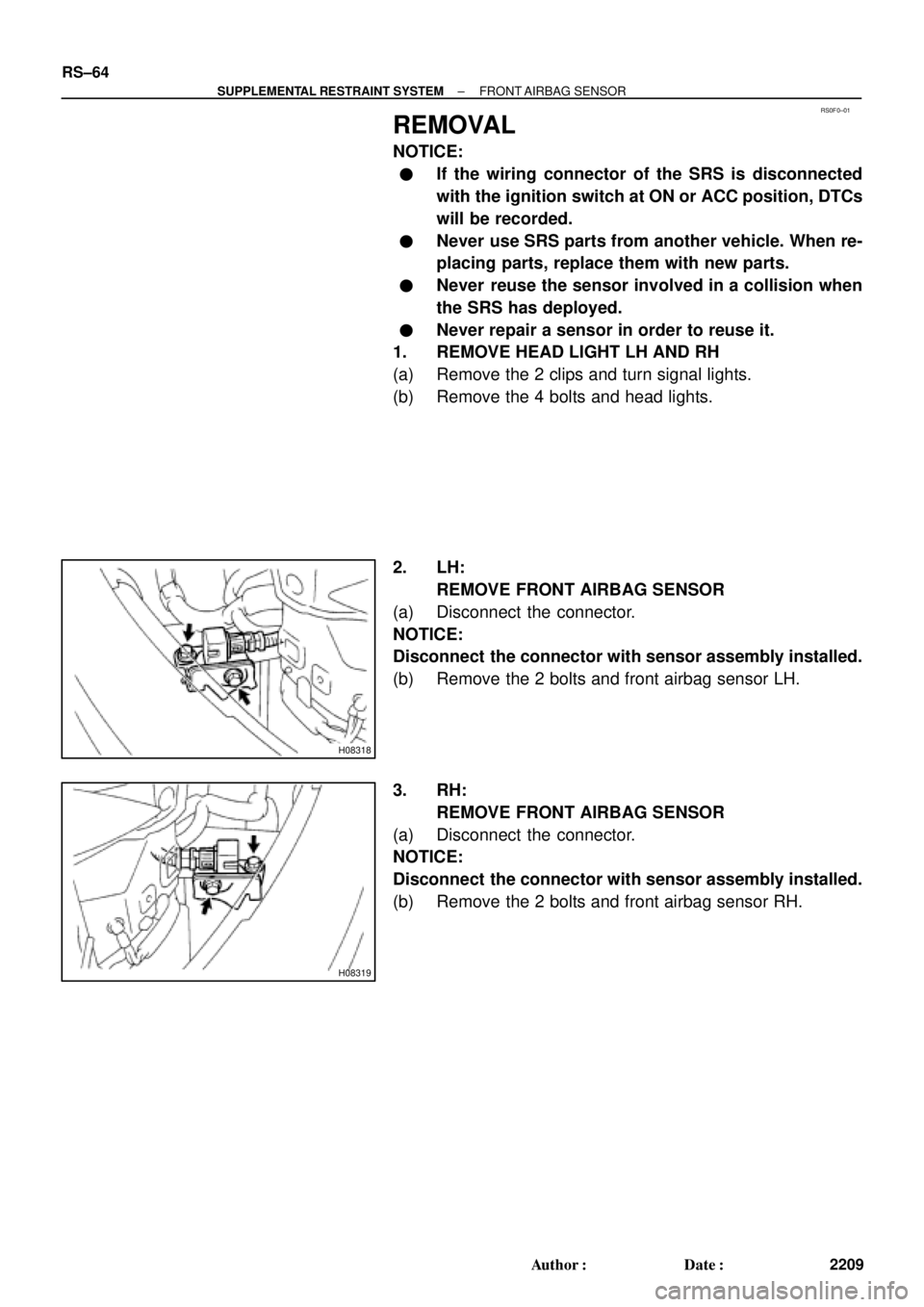
RS0F0±01
H08318
H08319
RS±64
± SUPPLEMENTAL RESTRAINT SYSTEMFRONT AIRBAG SENSOR
2209 Author�: Date�:
REMOVAL
NOTICE:
�If the wiring connector of the SRS is disconnected
with the ignition switch at ON or ACC position, DTCs
will be recorded.
�Never use SRS parts from another vehicle. When re-
placing parts, replace them with new parts.
�Never reuse the sensor involved in a collision when
the SRS has deployed.
�Never repair a sensor in order to reuse it.
1. REMOVE HEAD LIGHT LH AND RH
(a) Remove the 2 clips and turn signal lights.
(b) Remove the 4 bolts and head lights.
2. LH:
REMOVE FRONT AIRBAG SENSOR
(a) Disconnect the connector.
NOTICE:
Disconnect the connector with sensor assembly installed.
(b) Remove the 2 bolts and front airbag sensor LH.
3. RH:
REMOVE FRONT AIRBAG SENSOR
(a) Disconnect the connector.
NOTICE:
Disconnect the connector with sensor assembly installed.
(b) Remove the 2 bolts and front airbag sensor RH.
Page 4300 of 4770
F01476
Key Unlock Warning Switch
Column Upper Bracket Ignition Switch
Energy Absorbing PlateTransponder Key Coil Key Cylinder Lamp Assembly
Key
Interlock
Solenoid Key Cylinder
Transponder Key
Amplifier
Energy Absorbing Plate
Guide� Energy Absorbing Clip
Energy Absorbing Plate
Energy Absorbing Plate
Guide
� Energy Absorbing Clip Column TubeTilt Lever
Return Spring
� Tapered±Head Bolt Column Upper Tube Turn Signal Bracket
Lower Column Tube AttachmentColumn Tube Support
7 (70, 61 in.´lbf)
19 (195, 14)
N´m (kgf´cm, ft´lbf): Specified torque
� Non±reusable partw/ ENGINE IMMOBILISER SYSTEM:
A/T: SR±10
± STEERINGTILT STEERING COLUMN
2105 Author�: Date�:
Page 4304 of 4770

SR06K±01
W03335
Ignition Key
W03336
SR±14
± STEERINGTILT STEERING COLUMN
2109 Author�: Date�:
INSPECTION
1. INSPECT STEERING LOCK OPERATION
Check that the steering lock mechanism operates properly.
2. IF NECESSARY, REPLACE KEY CYLINDER
(a) Place the ignition key at the ACC position.
(b) Push down the stop pin with a screwdriver, and pull out
the cylinder.
(c) Install a new cylinder.
HINT:
Make sure the key is at the ACC position.
3. INSPECT IGNITION SWITCH
(See page BE±14)
4. IF NECESSARY, REPLACE IGNITION SWITCH
(a) Remove the 2 screws.
(b) Install a new switch with the 2 screws.
5. INSPECT KEY UNLOCK WARNING SWITCH
(See page BE±14)
6. IF NECESSARY, REPLACE KEY UNLOCK WARNING
SWITCH
(a) Slide out the switch.
(b) Install a new switch.
7. A/T:
INSPECT KEY INTERLOCK SOLENOID
(A140E: See page AX±13)
(A541E: See page AX±17)
8. A/T:
IF NECESSARY, REPLACE KEY INTERLOCK SOLE-
NOID
(a) Remove the 2 screws.
(b) Install a new solenoid with the 2 screws.
9. w/ ENGINE IMMOBILISER SYSTEM:
INSPECT TRANSPONDER KEY COIL
(See page BE±128)
10. w/ ENGINE IMMOBILISER SYSTEM:
IF NECESSARY, REPLACE TRANSPONDER KEY
COIL
11. w/ ENGINE IMMOBILISER SYSTEM:
IF NECESSARY, REPLACE TRANSPONDER KEY AM-
PLIFIER
(a) Remove the 2 screws.
(b) Install a new key amplifier with the 2 screws.
Page 4413 of 4770

REMOVAL
1. REMOVE S")
SR06I±05
F00879
Torx Screw
Screw Case
F00878
Airbag Connector
Correct Wrong
W03302
Matchmarks
SST
± STEERINGTILT STEERING COLUMN
SR±11
2096 Author�: Date�:
2001 CAMRY (RM819U)
REMOVAL
1. REMOVE STEERING WHEEL PAD
NOTICE:
If the airbag connector is disconnected with the ignition
switch at ON or ACC, DTCs will be recorded.
(a) Place the front wheels facing straight ahead.
(b) Remove the 2 steering wheel lower No.2 and No.3 cov-
ers.
(c) Using a torx socket wrench, loosen the 2 torx screws.
HINT:
Loosen the 2 screws until the groove along the screw circumfer-
ence catches on the screw case.
(d) Pull the pad out from the steering wheel and disconnect
the airbag connector.
CAUTION:
�When storing the wheel pad, keep the upper surface
of the pad facing upward.
�Never disassemble the wheel pad.
NOTICE:
When removing the wheel pad, take care not to pull the air-
bag wire harness.
2. REMOVE STEERING WHEEL
(a) Disconnect the connector.
(b) Remove the steering wheel set nut.
(c) Place matchmarks on the steering wheel and main shaft
assembly.
(d) Using SST, remove the wheel.
SST 09950±50012 (09951±05010, 09952±05010,
09953±05020, 09954±05020)
Page 4428 of 4770
TOYOTA VIP RS3000 PROGRAMMING ± ALL MODELS ± AX005±99 April 9, 1999
Page 2 of 4
For location of the RS3000 ECU, refer to ECU Mounting Locations, Page 4.
I. To program (add) a REMOTE CONTROL to the system:
1. Insert the key into ignition switch,
and turn it to ªONº.
2. Press and hold the ECU's
PROGRAMMING SWITCH for 3
seconds.
The STATUS MONITOR LED
turns on for 5 seconds.
NOTE:
YOU MUST PERFORM THE NEXT
STEP WITHIN 5 SECONDS.
3. Press and release a REMOTE
CONTROL's top or bottom
button.*
The STATUS MONITOR LED
turns off.
The Piezo ªchirperº chirps once.
The exterior lights flash once.
4. Turn off the ignition. The ECU will
now operate with the REMOTE
CONTROL just programmed.
* Either button on your REMOTE CONTROL can be programmed to operate the system. The bottom
button can be programmed to operate a second vehicle with the Toyota VIP.
Programming
Procedure
Press and Hold
for 3 Seconds
Lights Up
Press Once

 a REMOTE CONTROL to the")