Page 1497 of 4770

J OVERALL ELECTRICAL WIRING DIAGRAM
1
234
26 CAMRY
1F 2F
1A 1A
1B 40A
AM1
1B 11K 22ACC
IG1 AM1 4
10A
MIRROR±
HEAT ER
1 0 A HEAT ER 15A ECU±I G
40A DEF
30A
RDI30A
CDS
1T 5 1D 41J71R 31A6
2H 2
5IM1 5IE1
8ID11L 11J12
1V 3
IJ Right kic k
panelIE Co wl s i de
panel LHIGInstrument
panel brace
LHBORi ght quart er
pillar 20 IE1
20 IM11K 1 1B 4
2K 62B2
1 2
M
2 1
3 4
2 1
3 53 5
2 1
4
2F 4 2C 2 1J 13
1G 72 3
1 2
2EA1 1EA1
1 2
5 3
4 1 1
1 11 2G 7 2F 2 2C 12G1
1 2
5 3
1 2
M 11
11 5IK1
L±B L±B B±R
1II1
1
EBLef t radiat or
side supportG±W
B±R(
*1)
W±R
W± B
B±R W± B
B±R
W± BL(
*1)
L(
*1)
B±W
(
*2)
G± W
L±W L±W W±B
W± B
B±RW±B W± B W± B
W± R
B±R R
G±W
L
L
B±R
B BY±G(
*8)
W± B
A
A11 1
2
A22
FAN NO. 2 RELAY
R 1
RA DI A TOR FA N MOT OR
FAN NO. 3 RELAY
W 5
WATER TEMP.
SW NO. 2 To Di o de(
A/ C)
<27±2><29±3>
A 3
A/ C SI NGLE
PRESSURE SWW 4
WATER TEMP.
SW NO. 1
J32
JUNCTI ON CONNECTOR
FAN NO. 1
RELAY
DEFOGGER
RELAYFro m MG CLT
Relay< 27±2>
AA
AA
J38
JUNCTION
CONNECTOR
J39
JUNCTION
CONNECTOR NOISE FILTER
B±Y
B±YB±Y
B±YW± B
W± B W± B
W± B W± B
W± B
W±B
B±G 100A ALT
B±R B±R
B±R B±R
I16
IGNITION SW
BATTERY FL MAIN
3. 0WFUSI BLE LINK BLOCK
B±R B±R
B± R
Power SourceR ear W indow Defogger and
M irror H ea terRadiator Fan and Condenser Fan
1DB±R B±R
B± Y B±Y
B±R
(
*2)
LL
(
*1) L L
(
*1)
ENGINE MAIN RELAY
2 1
2 1
3 5
W± B
1C 9 1C 61J11
To Engine Control
Module< 2±10>
AA
31
2J12
JUNCTION
CONNECTOR
B±Y
(
*2) G± OG±O
(
*2) B±Y
(
*1)
B± R
(
*2)
To Engine Cont rol
Module< 3±6>
W±B D11
DIODE
(
Idle±Up) 10A
TAIL
TAIL LI GHT RELAY
* 1 : 1MZ±FE
* 2 : 5S±FE
1 2
WJ11
JUNCTI ON
CONNE CTOR
See Taillight
Sy st em< 11±1>
2J 13
G± W
(
*1)To Engine Cont rol
Module< 2±11>
W± B
A 1
A/C CONDENSER
FAN MOTOR
AA
W± B3 54
L±B
W± B
DIG
E
R 5
REAR WINDOW
DEFOGGER SW
B±R2 1
NOISE FILTERREAR WI NDOW
DEFOGGER
N 2
NOISE FILTER
(
Rear Window
Def ogger)1B
B
(
*3)
(
*4)(
*3)
* 3 : w/ Auto Antenna
* 4 : w/o Auto Antenna
6B 1A
4B 5A(
*6) (
*5)
(
*6) (
*5)6B 1A
4B 5A(
*5)
(
*6)
(
*5)
(
*6)* 5 : TMC Made
* 6 : TMMK Made
MI RROR HEAT ER RH
[ REMOTE CONTROL
MI RROR LH]B A R1 6 ,
R17 ,
MIRROR HEATER RH
[ RE MOT E CONT ROL
MIRROR RH]AB
REAR WINDOW
DEFOGGERB A R14 R15,
D F 4 F 7A, FF 9 , (
*5)(
*5) W± B
(
*6)
(
*5)
(
*5)(
*5) W± B(
*6)(
*8)
To A/C Co ntr ol
Assembly< 29±5> Y±G
(
*7)
(
*8)* 7 : Automatic A/C
* 8 : Manual A/C
W±B
(
*6)
Page 1499 of 4770

L±B(
*2) Y
P24
PRETENSIONER LHA 1 67A 2ACC
IG1
IG2
ST 2 AM13
I16
IGNITION SW6 7AM2
1ACENTER AI RBAG SENSOR ASSEMBLY
,")
J OVERALL ELECTRICAL WIRING DIAGRAM
1
234
28 CAMRY
28
,
B 10AB
2
12A
Y± B(
*1)
L±B(
*2) Y
P24
PRETENSIONER LHA 1 67A 2ACC
IG1
IG2
ST 2 AM13
I16
IGNITION SW6 7AM2
1ACENTER AI RBAG SENSOR ASSEMBLY
,
1B 1
1F 1C
40A AM1
1K 2
2A 1
10A ECU±B
2J 7
42L
30A
AM2
B± G
1B 51K 5
SHORT
PIN
100A
ALT1K 3
A23
AIRBAG SQUIB
(
Steering
Wheel Pad)
IG1N 4
1N 11W 3
1G 2
1J 7
Co wl s i de
panel LH IE A1N 3
1V 3 12
SPI RAL
CABLE
12BA
S 9
SIDE AI RBAG
SQUI B LH
Y±G
Y±R
B±RB
W±R
W±R
W
W
B± RL±RW± R
B±O
A
2 1
LG
FL MAIN
3. 0W
BATTERY
W± B
W± RW± BW± B
5
Y±BY Y±R Y±G W± B
1 213 12
J11
JUNCTION
CONNECTORA2 2
AI RBAG SQUIB
(
Fr ont Pas senger
Airbag Assembly)W± R
W± RC 9
SRS WARNING LIGHT
[COMB. METER]
B
FUSIBLE LINK
BLOCKF F 9 C F 6 A F 4
11
I nst rument panel
brace LH 1 2
, C18 C1 7 C, C19 5B1K 6
1N 2GR6BA 910A12A 1234S 7
SI DE AIRBAG SENSOR LH
12 C C10 9C 7C 1234
GR±L
S 8
SIDE AI RBAG SENSOR RH
P±L L±W LG±BP L±YLG GR
A
P±B
LG B± Y(
*4)
LG(
Except * 4)
To Data Link Connec tor 1, 2
< 18±4> < 19±3> < 20±3> < 20±4>
3B 19BA
P± B
B± Y J 3
JUNCTION
CONNECTOR
2
12CY±R Y±GS10
SIDE AIRBAG
SQUIB RHC 15
12C
Y±BY
P25
PRET ENSI ONER RHC 6 14 B 13 B 27 B
Power SourceSRS
To Data Link Connect or 3
< 2±3> < 3±8>12 B
W
±SL2IG27II3
W± R
B 26
B± W
BR±W
15 B
B±W
20 B
BR
9B 2IT1 1IU1 IU122 1 2 1
BR±W
W± R
BR
A31
AIRBAG SENSOR
FRONT L HA3 2
AI RBAG SENSOR
FRONT RH
(
*3)
(
*3) (
*3)
(
*3)
(
*1 *3) (
*1 *3) (
*1 *3)
(
*1 *3)
2F+SRB±R B±R
±SR +SL* 1 : TMC Made
* 2 : TMMK Made
* 3 : w/ Side Airbag
(
*3) (
*3) (
*3) (
*3)VUPR SSR+ FSR ESR VUPL SSL+ FSL ESLLA TC
SFL+ SFL± PL+ PL± SFR+ SFR± PR+ PR± E2 SIL E1 D+ D± P+ P±IG2 ACC
1 BV1 2 BV1 1 BW1 2 BW1
Y±R Y±GY±R Y±G
Y±R Y±GY±R Y±G
(
*2 *3)(
*2 *3) (
*2 *3)(
*2 *3) (
*2 *3)(
*2 *3) (
*2 *3)(
*2 *3)
A
LG * 4 : TMMK Made 1MZ±FE
AABB
CONNECTION
DETECTION
PINCONNE CTI ON
DE TE CTI ON
PI N
5A
IGN15A
CIG
1IT1
Page 1501 of 4770

2ACC
IG1 AM1 4
1K 2
40A
AM1
1B 1 1V 10
1W 3
2J 7
2 1
3 5
41 1
1 1 1 10A
ECU±B
2A 1
1E 1F 2F
1A1 EB2
EB Left radiator
s ide suppo")
J OVERALL ELECTRICAL WIRING DIAGRAM
1
234
29 CAMRY(
Cont. next page)
2ACC
IG1 AM1 4
1K 2
40A
AM1
1B 1 1V 10
1W 3
2J 7
2 1
3 5
41 1
1 1 1 10A
ECU±B
2A 1
1E 1F 2F
1A1 EB2
EB Left radiator
s ide supportEB12
6 2
IGInst rument panel
brace LH1K 1
2 1
3 5 11
1110A
HEAT ER
1R 3 1W 2
2K 5 2C 9
IK27B
C
D
E
G
H
I
J F L±B L±B
L±W L±W
W± BB±W
W± B
L±B
W± B
W± B B±WL±Y L±WL±B
L±YW± R
A
L±B B±Y
L±W
L±R
W± B
W± R W± RB±R B±RB±RL±B
B±G B±W
L±WL±B L±B
L±B
L±B
W
I16
IGNITION SW
SHORT
PINHTR
RELAY
FL MAIN
3. 0W
B 8
BLOWER RESI STOR
(
Low Speed)
A3 3
A/C BLOWER MOTOR
LINEAR CONTROLLER
W± B
J11
JUNCTI ON
CONNE CTOR BATTERY32
D 3
DI ODE(
A/C)
Power SourceA ir Conditioning (
Automatic A/C)100A
ALT50A
HTR 1 2MG CLT
RE L AY
Fro m FAN NO. 3
Relay< 26±3>1
L 12
FUSIBLE LINK BLOCKC A F 4 F 6, EF 8 , FF 9 ,
M 12
IICowl si de
panel RH L±R
L±R B±W
W±BW±B B±W
W±B L±R
B±W
W± B B±W
43
A2
A1 B 3
BLOWER MOTOR
B± WJ32
JUNCTION
CONNECTOR A
AA
W± B
A A
B1CW
GND VM +B
SI
W± B
EBLef t radiat or
side support W± B
Page 2450 of 4770
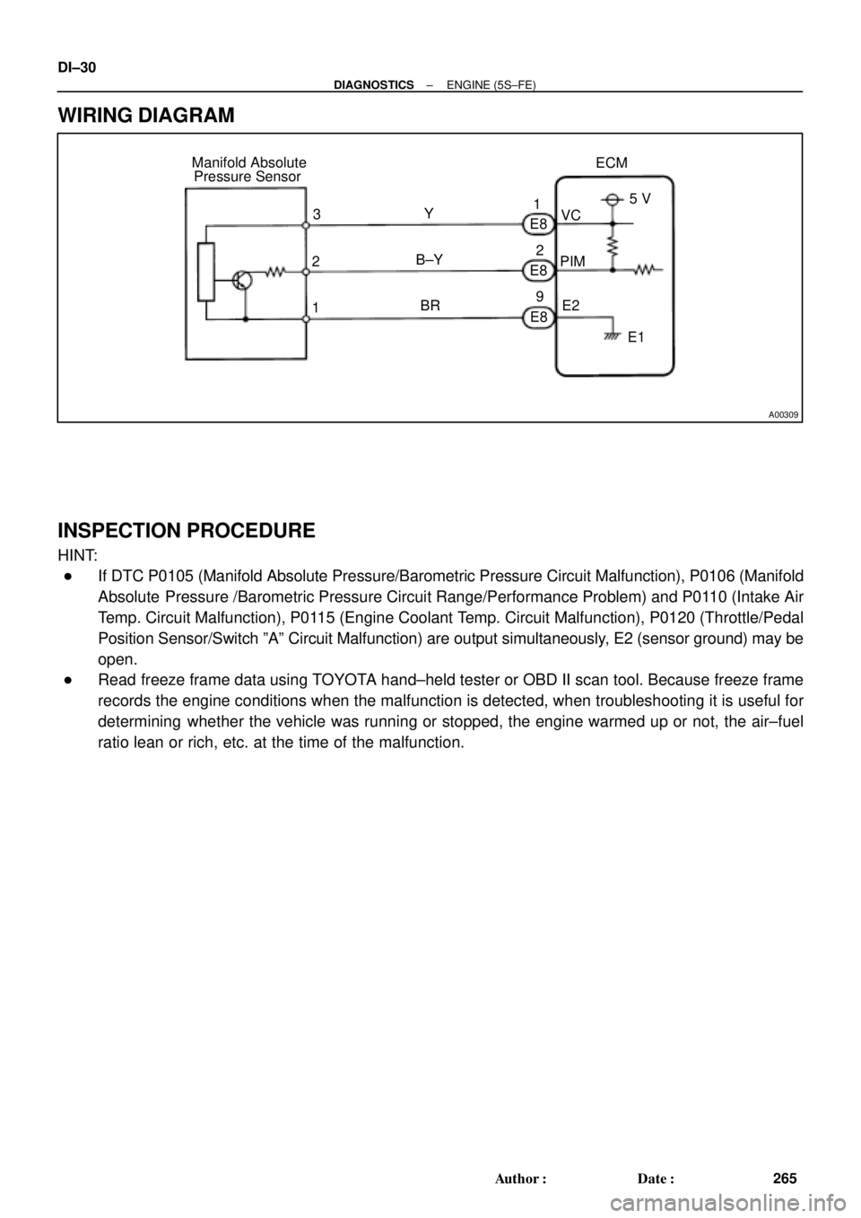
A00309
ECM Manifold Absolute
Pressure Sensor
1PIMVC
E2 Y
B±Y
BRE8
E8
E8 3
25 V
E1 1
2
9 DI±30
± DIAGNOSTICSENGINE (5S±FE)
265 Author�: Date�:
WIRING DIAGRAM
INSPECTION PROCEDURE
HINT:
�If DTC P0105 (Manifold Absolute Pressure/Barometric Pressure Circuit Malfunction), P0106 (Manifold
Absolute Pressure /Barometric Pressure Circuit Range/Performance Problem) and P0110 (Intake Air
Temp. Circuit Malfunction), P0115 (Engine Coolant Temp. Circuit Malfunction), P0120 (Throttle/Pedal
Position Sensor/Switch ºAº Circuit Malfunction) are output simultaneously, E2 (sensor ground) may be
open.
�Read freeze frame data using TOYOTA hand±held tester or OBD II scan tool. Because freeze frame
records the engine conditions when the malfunction is detected, when troubleshooting it is useful for
determining whether the vehicle was running or stopped, the engine warmed up or not, the air±fuel
ratio lean or rich, etc. at the time of the malfunction.
Page 2453 of 4770

DI±33
268 Author�: Date�:
DTC P0106 Manifold Absolute Pressure Circuit
Range/Performance Problem
CIRCUIT DESCRIPTION
Refer to DTC P0105 (Manifold Absolute Pressure/Barom")
± DIAGNOSTICSENGINE (5S±FE)
DI±33
268 Author�: Date�:
DTC P0106 Manifold Absolute Pressure Circuit
Range/Performance Problem
CIRCUIT DESCRIPTION
Refer to DTC P0105 (Manifold Absolute Pressure/Barometric Pressure Circuit Malfunction) on page
DI±29.
DTC No.DTC Detecting ConditionTrouble Area
P0106
After engine is warmed up, conditions (a) and (b) continue with
engine speed 400 ~ 1,000 rpm
(2 trip detection logic)
(a) Throttle valve fully closed
(b) Manifold absolute pressure sensor output > 3.0 V
�Manifold absolute pressure sensorP0106Condition (c) and (d) continue with engine speed 2,500 rpm or
less
(2 trip detection logic)
(c) VTA > 1.85
(d) Manifold absolute pressure sensor output < 1.0 V
�Manifold absolute ressure sensor
�Vacuum line
WIRING DIAGRAM
Refer to DTC P0105 (Manifold Absolute Pressure/Barometric Pressure Circuit Malfunction) on page
DI±29.
INSPECTION PROCEDURE
HINT:
�If DTC P0105 (Manifold Absolute Pressure/Barometric Pressure Circuit Malfunction) and P0106 (Man-
ifold Absolute Pressure /Barometric Pressure Circuit Range/Performance Problem) are output simul-
taneously, manifold absolute pressure sensor circuit may be open. Perform troubleshooting of DTC
P0105 first.
�If DTC P0105 (Manifold Absolute Pressure/Barometric Pressure Circuit Malfunction), P0106 (Manifold
Absolute Pressure /Barometric Pressure Circuit Range/Performance Problem), P0110 (Intake Air
Temp. Circuit Malfunction), P0115 (Engine Coolant Temp. Circuit Malfunction) and P0120 (Throttle/
Pedal Position Sensor/Switch ºAº Circuit Malfunction) are output simultaneously, E2 (sensor ground)
may be open.
�Read freeze frame data using TOYOTA hand±held tester or OBD II scan tool. Because freeze frame
records the engine conditions when the malfunction is detected, when troubleshooting it is useful for
determining whether the vehicle was running or stopped, the engine warmed up or not, the air±fuel
ratio lean or rich, etc. at the time of the malfunction.
1 Are there any other codes (besides DTC P0106) being output?
YES Go to relevant DTC chart.
NO
DI00N±04
Page 2456 of 4770
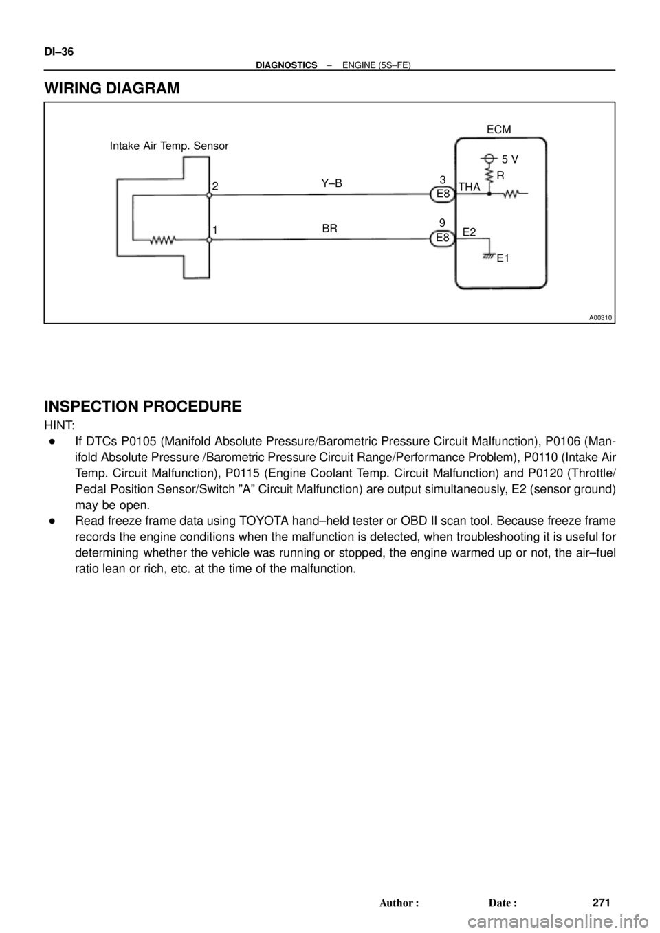
A00310
Intake Air Temp. Sensor
E8
E83
9ECM
5 V
THA
E2
E1 R
Y±B
BR 2
1 DI±36
± DIAGNOSTICSENGINE (5S±FE)
271 Author�: Date�:
WIRING DIAGRAM
INSPECTION PROCEDURE
HINT:
�If DTCs P0105 (Manifold Absolute Pressure/Barometric Pressure Circuit Malfunction), P0106 (Man-
ifold Absolute Pressure /Barometric Pressure Circuit Range/Performance Problem), P0110 (Intake Air
Temp. Circuit Malfunction), P0115 (Engine Coolant Temp. Circuit Malfunction) and P0120 (Throttle/
Pedal Position Sensor/Switch ºAº Circuit Malfunction) are output simultaneously, E2 (sensor ground)
may be open.
�Read freeze frame data using TOYOTA hand±held tester or OBD II scan tool. Because freeze frame
records the engine conditions when the malfunction is detected, when troubleshooting it is useful for
determining whether the vehicle was running or stopped, the engine warmed up or not, the air±fuel
ratio lean or rich, etc. at the time of the malfunction.
Page 2462 of 4770
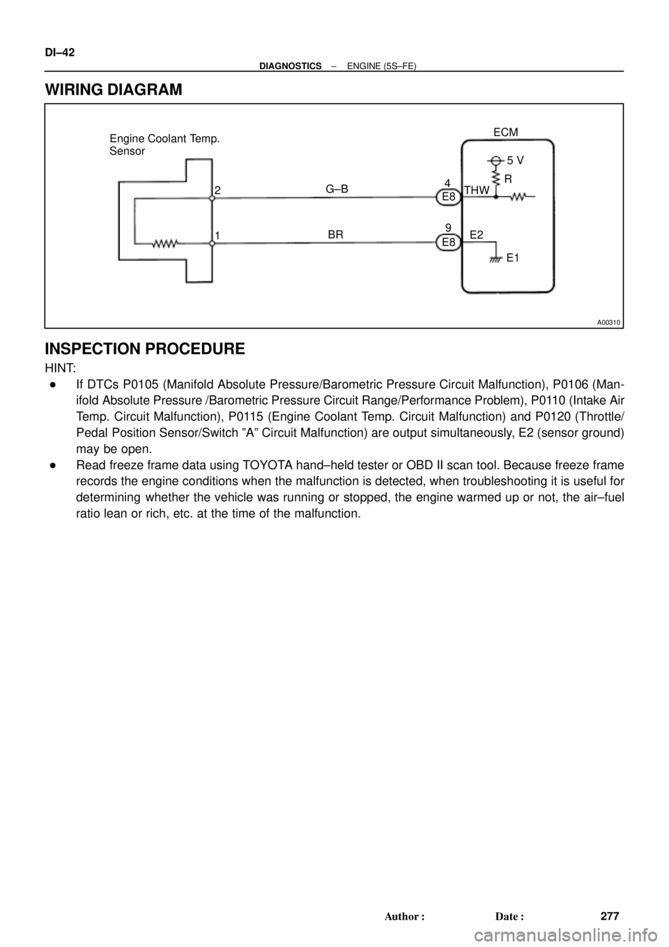
A00310
Engine Coolant Temp.
Sensor
2
1ECM
G±B
BR4
E8
E895 V
THW
E2
E1 R DI±42
± DIAGNOSTICSENGINE (5S±FE)
277 Author�: Date�:
WIRING DIAGRAM
INSPECTION PROCEDURE
HINT:
�If DTCs P0105 (Manifold Absolute Pressure/Barometric Pressure Circuit Malfunction), P0106 (Man-
ifold Absolute Pressure /Barometric Pressure Circuit Range/Performance Problem), P0110 (Intake Air
Temp. Circuit Malfunction), P0115 (Engine Coolant Temp. Circuit Malfunction) and P0120 (Throttle/
Pedal Position Sensor/Switch ºAº Circuit Malfunction) are output simultaneously, E2 (sensor ground)
may be open.
�Read freeze frame data using TOYOTA hand±held tester or OBD II scan tool. Because freeze frame
records the engine conditions when the malfunction is detected, when troubleshooting it is useful for
determining whether the vehicle was running or stopped, the engine warmed up or not, the air±fuel
ratio lean or rich, etc. at the time of the malfunction.
Page 2470 of 4770

E8 E810
(*1)
DI±50
± DIAGNOSTICSENGINE (5S±FE)
285 Author�: Date�:
WIRING DIAGRAM")
A03595
Throttle Position Sensor
ECM
E8
E8 1
3
2Y
LG
BR1
11
9VC
VTA
E25 V
*1: w/o Immobiliser
*2: w/ Immobiliser(*2)
E8 E810
(*1)
DI±50
± DIAGNOSTICSENGINE (5S±FE)
285 Author�: Date�:
WIRING DIAGRAM
INSPECTION PROCEDURE
HINT:
�If DTCs P0105 (Manifold Absolute Pressure/Barometric Pressure Circuit Malfunction), P0106 (Man-
ifold Absolute Pressure /Barometric Pressure Circuit Range/Performance Problem), P0110 (Intake Air
Temp. Circuit Malfunction), P0115 (Engine Coolant Temp. Circuit Malfunction) and P0120 (Throttle/
Pedal Position Sensor/Switch ºAº Circuit Malfunction) are output simultaneously, E2 (sensor ground)
may be open.
�Read freeze frame data using TOYOTA hand±held tester or OBD II scan tool. Because freeze frame
records the engine conditions when the malfunction is detected, when troubleshooting it is useful for
determining whether the vehicle was running or stopped, the engine warmed up or not, the air±fuel
ratio lean or rich, etc. at the time of the malfunction.