Page 2599 of 4770
A07554
ECM
+B 12
E7 B±Y J/C
B
J28 J27B
B±Y
Instrument
Panel J/B 22J 2K7
W±R EFI
Relay 1 3
52
2F4
W±B
2A 1
AM2
42L
B
FL
Block
MAIN
FL
B±GEngine
J/B No.2
5
1B
531K71W
IGN
1K
Room
W±R
IG
Switch
7 6
14
E9
BR
B±R
EC
E1
F6
F4EB
B±R
1
1
EFI
J23
J/C A
A
Battery
BR
(*2) (*1)
*1: w/ Immobiliser
*2: w/o ImmobiliserE924 (*2)
MREL 7
E10 B±Y (*1) 6II4 B±W (*1)
± DIAGNOSTICSENGINE (5S±FE)
DI±179
414 Author�: Date�:
ECM Power Source Circuit
CIRCUIT DESCRIPTION
When the ignition switch is turned ON, battery positive voltage is applied to the coil, closing the contacts of
the EFI main relay (Marking: EFI) and supplying power to terminal +B of the ECM.
WIRING DIAGRAM
DI01L±05
Page 2604 of 4770
A07555
Battery
EFI
AM2
123
3 1J
B2A
2J Instrument Panel J/B
B
1B 1W
37
1 5
IG Switch
1
B±W
B±RST RelayEFI Relay
5
6
2 3
1 11 410
4
5 4
5
A 2B STARTER
(M/T)
B±G
II23
B±W
II211
Starter
Park/Neutral
Position Switch
Clutch Start
Switch
5 7
B±R Engine Room J/B No.2
2C
2F IGN
FL Block1
2D1
BMAIN
B±O (*3) W±B
GR (*2)
10B
C
1
CIR
OPN
Relay
L±B
IGG±R
W±B
14 2L
E7FCECM
E01
1
S1S2
Engine Room R/B
No.1
2
J40
J/C
G±RL±B
5 93
Fuel
Pump
L±B
R
EB B±R
GR
W±R
B±W
B±WB±O (*3)(A/T)
BL
J/CB±R
J8
2K
J7
B
1 1 1
B 1K
1K
1K
8 7
6
EB1 4
J29
J/C J11
J/CF6 1 W±R
MAIN
FL4
5 2K
2
B±R (*4)
*1: w/ Immobiliser(*1)
MREL
E107 B±W
B
B
B±WII4
6
F41
GR (*2)
*2: TMC Made
*3: TMMK Made A
(*1)
(*1)
GR (*2)
B±O (*3)(M/T)
*4: w/o Immobiliser
EB1 B±R
B±R (*1)
B±R (*4)
IK17
55
7
ID1
7 W±B
W±B
DI±184
± DIAGNOSTICSENGINE (5S±FE)
419 Author�: Date�:
WIRING DIAGRAM
Page 2610 of 4770
A03610
9
W±L
IK2
E9 10
II3
E9 18
LOCK IN
E1 14
EC
BRJ23
IK2 10
BR 1
2A/C Compressor
Lock SensorECM
BR W±L W±L
B
B BRJ/C
AA
A
BR
II3 J8
6J/C
*1: w/o Immobiliser
*2: w/ Immobiliser(*1) (*2)
E919
BR
E9 24
(*1) (*2)
DI±190
± DIAGNOSTICSENGINE (5S±FE)
425 Author�: Date�:
A/C Compressor Lock Sencor Circuit
CIRCUIT DESCRIPTION
This sensor sends 1 pulse par engine revolution to the ECM. If the number ratio of the compressor speed
divided by the engine speed is smaller than a predetermined value, the ECM turns the compressor off. And,
the indicator flashes at about 1 second intervals.
WIRING DIAGRAM
INSPECTION PROCEDURE
1 Check compressor.
PREPARATION:
(a) Check the compressor drive belt tension (See page AC±16).
(b) Check if the compressor does not lock during operation with the engine started and blower switch and
A/C switch ON.
NG Adjust drive belt tension or repair compressor
(See page AC±17).
OK
DI01N±04
Page 2612 of 4770
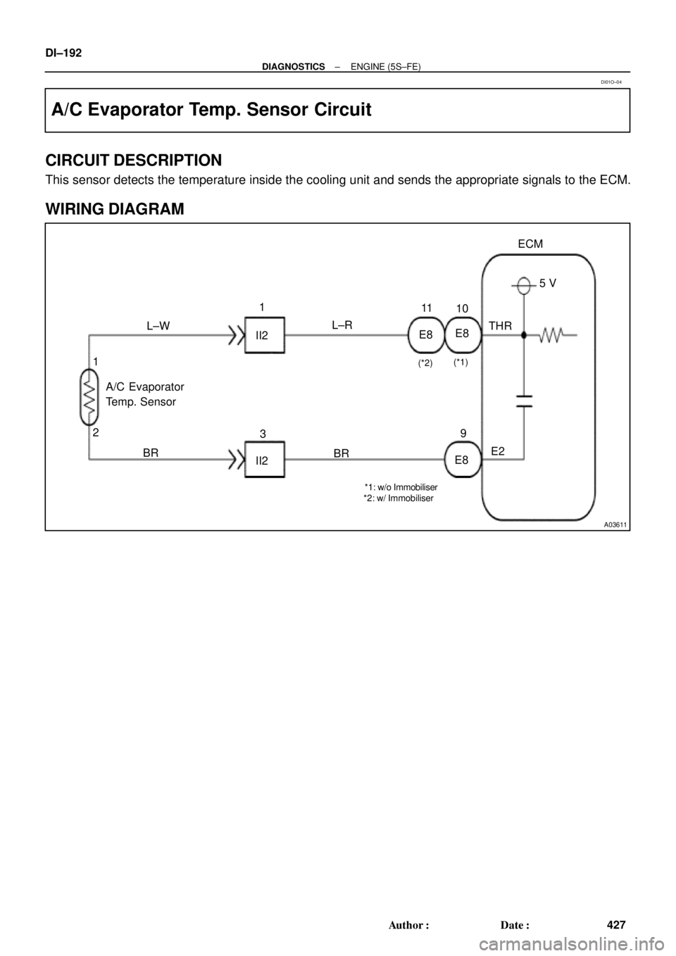
A03611
E8
II2 L±W1
L±R11
THR5 V ECM
E2
E89
BR
II23
BR A/C Evaporator
Temp. Sensor
2 1
*1: w/o Immobiliser
*2: w/ Immobiliser(*1)
(*2)
E810 DI±192
± DIAGNOSTICSENGINE (5S±FE)
427 Author�: Date�:
A/C Evaporator Temp. Sensor Circuit
CIRCUIT DESCRIPTION
This sensor detects the temperature inside the cooling unit and sends the appropriate signals to the ECM.
WIRING DIAGRAM
DI01O±04
Page 2643 of 4770
A06156
Engine Room J/B
EFI Relay
Junction
Connector
J20
Junction
Connector EFI
2A
2K2J
2C B
EB
7 1
2
5
13
2
F9
F4
11
B±G
Mass Air
Flow Meter
B±Y
B±Y
B±Y
R
R±BECM
E2GVG
E2 P 5B
B
9
4 A A
5
3
8
W±B
E10 B±W
E7 10
19
MRELB+ E10 Junction
ConnectorJ35 J36
A
A
B±W
Fusible
Link
Block
FL
MAIN
Battery
J27J28
II3
± DIAGNOSTICSENGINE (1MZ±FE)
DI±223
458 Author�: Date�:
WIRING DIAGRAM
INSPECTION PROCEDURE
HINT:
Read freeze frame data using TOYOTA hand±held tester or OBD II scan tool. Because freeze frame records
the engine conditions when the malfunction is detected, when troubleshooting it is useful for determining
whether the vehicle was running or stopped, the engine warmed up or not, the air±fuel ratio lean or rich, etc.
at the time of the malfunction.
Page 2647 of 4770

DI±227
462 Author�: Date�:
DTC P0101 Mass Air Flow Circuit Range/Performance
Problem
CIRCUIT DESCRIPTION
Refer to DTC P0100 (Mass Air Flow Circuit Malfunction) on page")
± DIAGNOSTICSENGINE (1MZ±FE)
DI±227
462 Author�: Date�:
DTC P0101 Mass Air Flow Circuit Range/Performance
Problem
CIRCUIT DESCRIPTION
Refer to DTC P0100 (Mass Air Flow Circuit Malfunction) on page DI±222.
DTC No.DTC Detecting ConditionTrouble Area
P0101
Conditions (a), (b) and (c) continue 10 sec. or more with
engine speed NE < 900:
(2 trip detection logic)
(a) Throttle valve fully closed
(b) Mass air flow meter output � 2.2 V
(c) THW � 70°C
�Mass air flow meterP0101
Conditions (a) and (b) continue 10 sec. or more with engine
speed 1,500 rpm or more:
(2 trip detection logic)
(a) VTA � 0.63 V
(b) Mass air flow meter output � 1.06 V
�Mass air flow meter
WIRING DIAGRAM
Refer to DTC P0100 (Mass Air Flow Circuit Malfunction) on page DI±222.
INSPECTION PROCEDURE
HINT:
Read freeze frame data using TOYOTA hand±held tester or OBD II scan tool. Because freeze frame records
the engine conditions when the malfunction is detected, when troubleshooting it is useful for determining
whether the vehicle was running or stopped, the engine warmed up or not, the air±fuel ratio lean or rich, etc.
at the time of the malfunction.
1 Are there any other codes (besides DTC P0101) being output?
NO Replace mass air flow meter.
YES
Go to relevant DTC chart.
DI07G±06
Page 2649 of 4770
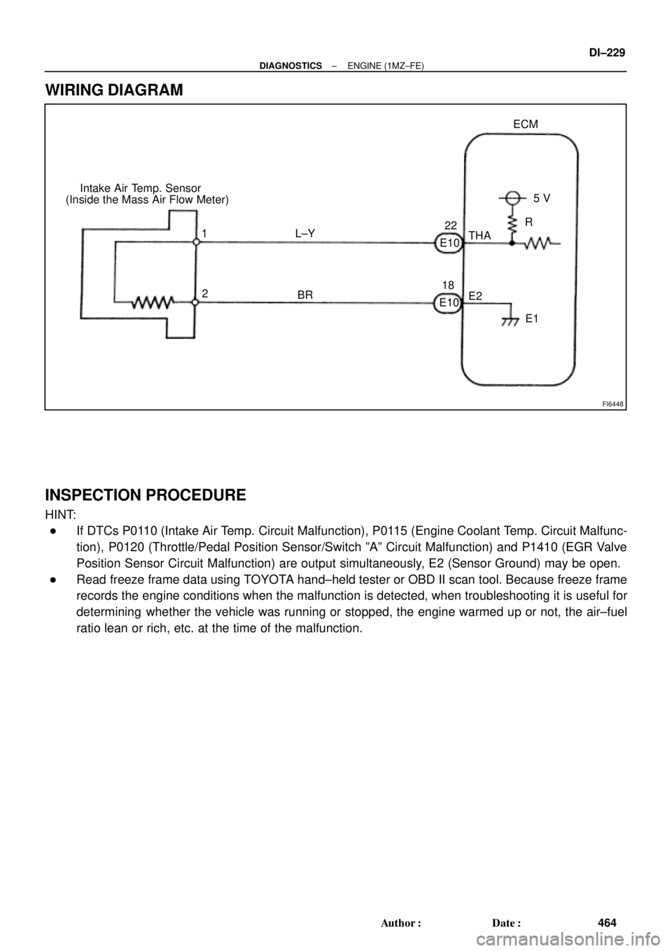
FI6448
Intake Air Temp. Sensor
(Inside the Mass Air Flow Meter)ECM
5 V
THA
E2
E1 1
2R
L±Y
BR
E10E1022
18
± DIAGNOSTICSENGINE (1MZ±FE)
DI±229
464 Author�: Date�:
WIRING DIAGRAM
INSPECTION PROCEDURE
HINT:
�If DTCs P0110 (Intake Air Temp. Circuit Malfunction), P0115 (Engine Coolant Temp. Circuit Malfunc-
tion), P0120 (Throttle/Pedal Position Sensor/Switch ºAº Circuit Malfunction) and P1410 (EGR Valve
Position Sensor Circuit Malfunction) are output simultaneously, E2 (Sensor Ground) may be open.
�Read freeze frame data using TOYOTA hand±held tester or OBD II scan tool. Because freeze frame
records the engine conditions when the malfunction is detected, when troubleshooting it is useful for
determining whether the vehicle was running or stopped, the engine warmed up or not, the air±fuel
ratio lean or rich, etc. at the time of the malfunction.
Page 2653 of 4770

DI±233
468 Author�: Date�:
DTC P0115 Engine Coolant Temp. Circuit Malfunction
CIRCUIT DESC")
FI6448
Engine Coolant Temp. SensorECM
5V
THW
E2
E1 2
1G±B
BR
E10
14
18
E10
± DIAGNOSTICSENGINE (1MZ±FE)
DI±233
468 Author�: Date�:
DTC P0115 Engine Coolant Temp. Circuit Malfunction
CIRCUIT DESCRIPTION
A thermistor built into the engine coolant temp. sensor changes the resistance value according to the engine
coolant temp.
The structure of the sensor and connection to the ECM is the same as in the intake air temp. circuit malfunc-
tion shown on page DI±228.
If the ECM detects the DTC P0115, it operates fail±safe function in which the engine coolant temperature
is assumed to be 80°C (176°F).
DTC No.Detection ItemTrouble Area
P0115Open or short in engine coolant temp. sensor circuit
�Open or short in engine coolant temp. sensor circuit
�Engine coolant temp. sensor
�ECM
HINT:
After confirming DTC P0115, use the OBD II scan tool or TOYOTA hand±held tester to confirm the engine
coolant temp. from CURRENT DATA.
Temperature DisplayedMalfunction
±40°C (±40°F)Open circuit
140°C (284°F) or moreShort circuit
WIRING DIAGRAM
INSPECTION PROCEDURE
HINT:
�If DTCs P0110 (Intake Air Temp. Circuit Malfunction), P0115 (Engine Coolant Temp. Circuit Malfunc-
tion), P0120 (Throttle/Pedal/Position Sensor/Switch ºAº Circuit Malfunction) and P1410 (EGR Valve
Position Sensor Circuit Malfunction) are output simultaneously, E2 (Sensor Ground) may be open.
�Read freeze frame data using TOYOTA hand±held tester or OBD II scan tool. Because freeze frame
records the engine conditions when the malfunction is detected, when troubleshooting it is useful for
determining whether the vehicle was running or stopped, the engine warmed up or not, the air±fuel
ratio lean or rich, etc. at the time of the malfunction.
DI07I±06


B±G
II23
B±W
II211
Starter
Park/Neutral")
 (*2)
E919
BR
E")