Page 2756 of 4770

P01559
Throttle Valve
From
Air
Cleaner
Signal
ECM
ValveIAC Valve
To Cylinders Intake Air Chamber
A07448
From
BatteryFL
MAIN
EC
F4 F611Fusible
Link
Block
B1
7 2
5EFI Engine Room J/B
EFI Relay1
23
5 2A
2K 2J
2C W±BIAC Valve
J27J28
B±Y
9II3
21
3E1116
15ECM
RSO
E01
RSC
E01 AA
B±W
MREL
B+ E11
E78
B±G
BB±YB±Y
J36
J35 AC J16
Junction
Connector
B±YR±W
Y±B
B±W
Junction
ConnectorB
Junction
Connector B DI±336
± DIAGNOSTICSENGINE (1MZ±FE)
571 Author�: Date�:
DTC P0505 Idle Control System Malfunction
CIRCUIT DESCRIPTION
The rotary solenoid type IAC valve is located in front of the in-
take air chamber and intake air bypassing the throttle valve is
directed to the IAC valve through a passage.
In this way the intake air volume bypassing the throttle valve is
regulated, controlling the engine speed.
The ECM operates only the IAC valve to perform idle±up and
provide feedback for the target idling speed.
DTC No.DTC Detecting ConditionTrouble Area
P0505Idle speed continues to vary greatly from target speed
(2 trip detection logic)
�IAC valve is stuck or closed
�Open or short in IAC valve circuit
�Open or short in A/C signal circuit
�Air intake (hose loose)
�ECM
WIRING DIAGRAM
DI083±06
Page 2760 of 4770

575 Author�: Date�:
DTC P1130 A/F Sensor Circuit Range/Performance Mal-
function (Only for California Spec.)
DTC P1150 A/F Sensor Circuit Range/Performance Mal-")
DI±340
± DIAGNOSTICSENGINE (1MZ±FE)
575 Author�: Date�:
DTC P1130 A/F Sensor Circuit Range/Performance Mal-
function (Only for California Spec.)
DTC P1150 A/F Sensor Circuit Range/Performance Mal-
function (Only for California Spec.)
CIRCUIT DESCRIPTION
Refer to DTC P0125 (Insufficient Temp. for Closed Loop Fuel Control (Only for California Spec.)) on Page
DI±249.
DTC No.DTC Detecting ConditionTrouble Area
Voltage output* of A/F sensor remains at 3.8 V or more, or
2.8 V or less, during engine running after engine is warmed
up (2 trip detection logic)
*: Output value changes at inside of ECM only.
P1130
P1150Voltage output* of A/F sensor does not change from 3.30 V,
during engine running after engine is warmed up
(2 trip detection logic)
*: Output value changes at inside of ECM only.�Open or short in A/F sensor (bank 1, 2 sensor 1) circuit
�A/F sensor (bank 1, 2 sensor 1)
�ECM
Open or short in A/F sensor circuit
(2 trip detection logic)
HINT:
�After confirming DTC P1130 or P01150, use the OBD II scan tool or TOYOTA hand±held tester to con-
firm voltage output of A/F sensor (AFS B1 S1/O2S B1 S1) from ºCURRENT DATAº.
�The A/F sensor's output voltage and the short±term fuel value can be read using the OBD II scan tool
or TOYOTA hand±held tester.
�The ECM controls the voltage of AFR/AFL� and AFR/AFL� terminals of ECM to the fixed voltage.
Therefore, it is impossible to confirm the A/F sensor output voltage without OBD II scan tool or TOYOTA
hand±held tester.
�OBD II scan tool (excluding TOYOTA hand±held tester) displays the one fifth of the A/F sensor output
voltage which is displayed on the TOYOTA hand±held tester.
WIRING DIAGRAM
Refer to DTC P0125 (Insufficient Coolant Temp. for Closed Loop Fuel Control (Only for California Spec.))
on page DI±249.
DI1K6±03
Page 2769 of 4770

HAFR (+)
± DIAGNOSTICSENGINE (1MZ±FE)
DI±349
584 Author�: Date�:
DTC P1135 A/F Sensor Heater Circuit Malfunction
(Bank 1 Sensor 1) (Only for California Spec.)
DTC P1155 A/F Sensor")
A02509
HAFL (+)
HAFR (+)
± DIAGNOSTICSENGINE (1MZ±FE)
DI±349
584 Author�: Date�:
DTC P1135 A/F Sensor Heater Circuit Malfunction
(Bank 1 Sensor 1) (Only for California Spec.)
DTC P1155 A/F Sensor Heater Circuit Malfunction
(Bank 2 Sensor 1) (Only for California Spec.)
CIRCUIT DESCRIPTION
Refer to DTC P0125 (Insufficient Coolant Temp. for Closed Loop Fuel Control (Only for California Spec.))
on page DI±249.
DTC No.DTC Detecting ConditionTrouble Area
P1135
When heater operates, heater current exceeds 8 A
(2 trip detection logic)�Open or in heater circuit of A/F sensors
(bank 1, 2 sensor 1)P1135
P1155Heater current of 0.25 A or less when heater operates
(2 trip detection logic)
(bank 1, 2 sensor 1)
�A/F sensors (bank 1, 2 sensor 1) heater
�ECM
WIRING DIAGRAM
Refer to DTC P0125 (Insufficient Coolant Temp. for Closed Loop Fuel Control (Only for California Spec.))
on page DI±249.
INSPECTION PROCEDURE
HINT:
Read freeze frame data using TOYOTA hand±held tester or OBD II scan tool. Because freeze frame records
the engine conditions when the malfunction is detected, when troubleshooting it is useful for determining
whether the vehicle was running or stopped, the engine warmed up or not, the air±fuel ratio lean or rich, etc.
at the time of the malfunction.
1 Check voltage between terminal HAFR, HAFL of ECM connector and body
ground.
PREPARATION:
(a) Remove glove compartment (See page SF±73).
(b) Turn the ignition switch ON.
CHECK:
Measure voltage between terminals HAFR, HAFL of the ECM
connector and body ground.
OK:
Voltage: 9 ~ 14 V
OK Check and replace ECM (See page IN±31).
NG
DI1K8±04
Page 2772 of 4770
S05723
J18
Junction
Connector
A
A A A AII3B±R
B±R B±R W±R128 3
1K 1C
Ignition
Switch
76
1K
1BB±R
G
B±R
B±R Y
LIgnition Coil
Spark Plug
No.1
No.2
No.3
11
12
2
2
ED
BR
3 2 1
10
9
7
6
5
4
W±R LG±B
BR±Y
IgniterECM
IGT1
IGT2
IGT3
IGF5 VInstrument
Panel J/B
E1125
E1113
E1112
E1111GR
B±R
5
5
W±R
Engine Room J/B
2L4
AM2
2A1
B
Fusible
Link
Block 1
1
F6
B±GFL
MAIN
Battery
F4
Instrument
Panel J/B
DI±352
± DIAGNOSTICSENGINE (1MZ±FE)
587 Author�: Date�:
WIRING DIAGRAM
INSPECTION PROCEDURE
HINT:
Read freeze frame data using TOYOTA hand±held tester or OBD II scan tool. Because freeze frame records
the engine conditions when the malfunction is detected, when troubleshooting it is useful for determining
whether the vehicle was running or stopped, the engine warmed up or not, the air±fuel ratio lean or rich, etc.
at the time of the malfunction.
1 Check spark plug and spark of misfiring cylinder (See page DI±276).
NG Go to step 4.
OK
Page 2777 of 4770

DI±357
592 Author�: Date�:
DTC P1335 Crankshaft Position Sensor Circuit
Malfunction (during engine running)
CIRCUIT DESCRIPTION
Refer to DTC P0335 (Crankshaft Position")
± DIAGNOSTICSENGINE (1MZ±FE)
DI±357
592 Author�: Date�:
DTC P1335 Crankshaft Position Sensor Circuit
Malfunction (during engine running)
CIRCUIT DESCRIPTION
Refer to DTC P0335 (Crankshaft Position Sensor ºAº Circuit Malfunction) on page DI±287.
DTC No.DTC Detecting ConditionTrouble Area
P1335No crankshaft position sensor signal to ECM with engine
speed 1,000 rpm or more
�Open or short in crankshaft position sensor circuit
�Crankshaft position sensor
�Starter
�ECM
WIRING DIAGRAM
Refer to DTC P0335 (Crankshaft Position Sensor ºAº Circuit Malfunction) on page DI±287.
INSPECTION PROCEDURE
Read freeze frame data using TOYOTA hand±held tester or OBD II scan tool. Because freeze frame records
the engine conditions when the malfunction is detected, when troubleshooting it is useful for determining
whether the vehicle was running or stopped, the engine warmed up or not, the air±fuel ratio lean or rich, etc.
at the time of the malfunction.
Refer to DTC P0335 (Crankshaft Position Sensor ºAº Circuit Malfunction) on page DI±287.
DI085±06
Page 2778 of 4770
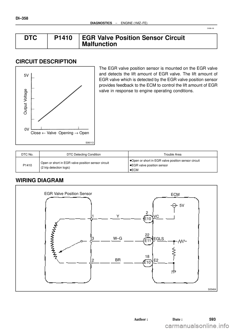
S06113
Close u Valve Opening " Open 0V 5V
Output Voltage
S05464
EGR Valve Position Sensor
3ECM
1
2Y
W±G
BRVC5V
EGLS
E2 E102
E1122
E1018 DI±358
± DIAGNOSTICSENGINE (1MZ±FE)
593 Author�: Date�:
DTC P1410 EGR Valve Position Sensor Circuit
Malfunction
CIRCUIT DESCRIPTION
The EGR valve position sensor is mounted on the EGR valve
and detects the lift amount of EGR valve. The lift amount of
EGR valve which is detected by the EGR valve position sensor
provides feedback to the ECM to control the lift amount of EGR
valve in response to engine operating conditions.
DTC No.DTC Detecting ConditionTrouble Area
P1410Open or short in EGR valve position sensor circuit
(2 trip detection logic)�Open or short in EGR valve position sensor circuit
�EGR valve position sensor
�ECM
WIRING DIAGRAM
DI086±06
Page 2783 of 4770
A07449
Fusible
Link
Block
FL
MAINStop Light Switch
B±G1B 1CSTOP
WG±WLight
Failure
Sensor 7
2
To Stop Light Instrument Panel J/B
Instrument Panel J/B
E7 15
G±W
1S 1R
1R1
2
F9
F4
BatteryECM
STP
E1 B±R
ALT
G±WA
C
J27Junction
Connector
J2845
2
G±W7 4
1
1
± DIAGNOSTICSENGINE (1MZ±FE)
DI±363
598 Author�: Date�:
DTC P1520 Stop Light Switch Signal Malfunction
(Only for A/T)
CIRCUIT DESCRIPTION
This signal is used to detect when the brakes have been applied. The STP signal voltage is the same as
the voltage supplied to the stop lights.
The STP signal is used mainly to control the fuel cut±off engine speed (The fuel cut±off engine speed is re-
duced slightly when the vehicle is braking.).
DTC No.DTC Detecting ConditionTrouble Area
P1520
Stop light switch does not turn off when repeating the driving at
30 km or more 10 times or more after depressing brake
(2 trip detection logic)�Short in stop light switch signal circuit
�Stop light switch
�ECM
WIRING DIAGRAM
DI088±06
Page 2786 of 4770

601 Author�: Date�:
DTC P1600 ECM BATT Malfunction
CIRC")
S05470
Battery FL
MAIN B±G
F4
F61 1
18
B Fusible
Link
BlockEngine Room J/B No.2
2A2JB±YECM
BATT EFI
E71 DI±366
± DIAGNOSTICSENGINE (1MZ±FE)
601 Author�: Date�:
DTC P1600 ECM BATT Malfunction
CIRCUIT DESCRIPTION
Battery positive voltage is supplied to terminal BATT of the ECM even when the ignition switch is OFF for
use by the DTC memory and air±fuel ratio adaptive control value memory, etc.
DTC No.DTC Detecting ConditionTrouble Area
P1600Open in back up power source circuit�Open in back up power source circuit
�ECM
HINT:
If DTC P1600 appear, the ECM does not store another DTC.
WIRING DIAGRAM
INSPECTION PROCEDURE
HINT:
Read freeze frame data using TOYOTA hand±held tester or OBD II scan tool. Because free frame records
the engine conditions when the malfunction is detected, when troubleshooting it is useful for determining
whether the vehicle was running or stopped, the engine warmed up or not, the air±fuel ratio lean or rich, etc.
at the time of the malfunction.
DI089±06