Page 2298 of 4770
P14433
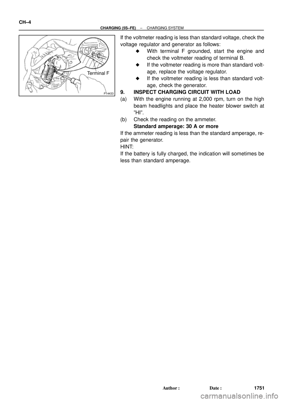
Terminal F CH±4
± CHARGING (5S±FE)CHARGING SYSTEM
1751 Author�: Date�:
If the voltmeter reading is less than standard voltage, check the
voltage regulator and generator as follows:
�With terminal F grounded, start the engine and
check the voltmeter reading of terminal B.
�If the voltmeter reading is more than standard volt-
age, replace the voltage regulator.
�If the voltmeter reading is less than standard volt-
age, check the generator.
9. INSPECT CHARGING CIRCUIT WITH LOAD
(a) With the engine running at 2,000 rpm, turn on the high
beam headlights and place the heater blower switch at
ºHIº.
(b) Check the reading on the ammeter.
Standard amperage: 30 A or more
If the ammeter reading is less than the standard amperage, re-
pair the generator.
HINT:
If the battery is fully charged, the indication will sometimes be
less than standard amperage.
Page 2311 of 4770
CHARGING SYSTEM
CH±1
1764 Author�: Date�:
CHARGING SYSTEM
ON±VEHICLE INSPECTION
CAUTI")
CH01D±01
Z11577
Except Maintenance±Free Battery
Z11556
Maintenance±Free BatteryVoltmeter
± CHARGING (1MZ±FE)CHARGING SYSTEM
CH±1
1764 Author�: Date�:
CHARGING SYSTEM
ON±VEHICLE INSPECTION
CAUTION:
�Check that the battery cables are connected to the
correct terminals.
�Disconnect the battery cables when the battery is
given a quick charge.
�Do not perform tests with a high voltage insulation
resistance tester.
�Never disconnect the battery while the engine is
running.
1. CHECK BATTERY ELECTROLYTE LEVEL
Check the electrolyte quantity of each cell.
(1) Maintenance±Free Battery:
If under the lower level, replace the battery (or add
distilled water if possible). Check the charging sys-
tem.
(2) Except Maintenance±Free Battery:
If under the lower level, add distilled water.
2. Except Maintenance±Free Battery:
CHECK BATTERY SPECIFIC GRAVITY
Check the specific gravity of each cell.
Standard specific gravity: 1.25 ± 1.29 at 20°C (68°F)
If the specific gravity is less than specification, charge the bat-
tery.
3. Maintenance±Free Battery:
CHECK BATTERY VOLTAGE
(a) After having driven the vehicle and in the case that 20
minutes have not passed after having stopped the en-
gine, turn the ignition switch ON and turn on the electrical
system (headlight, blower motor, rear defogger etc.) for
60 seconds to remove the surface charge.
(b) Turn the ignition switch OFF and turn off the electrical sys-
tems.
(c) Measure the battery voltage between the negative (±)
and positive (+) terminals of the battery.
Standard voltage: 12.5 ± 12.9 V at 20°C (68°F)
If the voltage is less than specification, charge the battery.
Page 2312 of 4770

Z18811
Maintenance±Free Battery
Type A
Type B
Blue White Red
OK Charging
NecessaryInsufficient
Water
GREEN EYE DARK EYECLEAR EYE or
CHARGED DISCHARGED ADD WATERLIGHT YELLOW
Z00015
Z00038
DENSO
Borroughs
CH0086
CORRECT WRONG CH±2
± CHARGING (1MZ±FE)CHARGING SYSTEM
1765 Author�: Date�:
HINT:
Check the indicator as shown in the illustration.
4. CHECK BATTERY TERMINALS, FUSIBLE LINK AND
FUSES
(a) Check that the battery terminals are not loose or cor-
roded.
If the terminals are corroded, clean the terminals.
(b) Check the fusible link, H±fuses, M±fuse and fuses for
continuity.
5. INSPECT DRIVE BELTS
(a) Visually check the drive belt for excessive wear, frayed
cords etc.
If any defect has been found, replace the drive belt.
HINT:
Cracks on the rib side of a drive belt are considered acceptable.
If the drive belt has chunks missing from the ribs, it should be
replaced.
(b) Using a belt tension gauge, measure the belt tension.
Belt tension gauge:
DENSO BTG±20 (95506±00020)
Borroughs No. BT±33±73F
Drive belt tension:
New belt175 ± 5 lbf
Used belt115 ± 20 lbf
If the belt tension is not as specified, adjust it.
HINT:
�ºNew beltº refers to a belt which has been used less than
5 minutes on a running engine.
�ºUsed beltº refers to a belt which has been used on a run-
ning engine for 5 minutes or more.
�After installing a belt, check that it fits properly in the
ribbed grooves.
�Check with your hand to confirm that the belt has not
slipped out of the groove on the bottom of the pulley.
Page 2313 of 4770
CHARGING SYSTEM
CH±3
1766 Author�: Date�: �
After installing a new belt, run the engine for about 5 min-")
Z03473
BatteryAmmeter
VoltmeterDisconnect Wire
from Terminal B
Generator
± CHARGING (1MZ±FE)CHARGING SYSTEM
CH±3
1766 Author�: Date�: �
After installing a new belt, run the engine for about 5 min-
utes and recheck the belt tension.
6. VISUALLY CHECK GENERATOR WIRING AND
LISTEN FOR ABNORMAL NOISES
(a) Check that the wiring is in good condition.
(b) Check that there is no abnormal noise from the generator
while the engine is running.
7. CHECK DISCHARGE WARNING LIGHT CIRCUIT
(a) Warm up the engine and then turn it off.
(b) Turn off all accessories.
(c) Turn the ignition switch ºONº. Check that the discharge
warning light is lit.
(d) Start the engine. Check that the light goes off.
If the light does not go off as specified, troubleshoot the dis-
charge light circuit.
8. INSPECT CHARGING CIRCUIT WITHOUT LOAD
HINT:
If a battery/generator tester is available, connect the tester to
the charging circuit as per manufacturer's instructions.
(a) If a tester is not available, connect a voltmeter and amme-
ter to the charging circuit as follows:
�Disconnect the wire from terminal B of the genera-
tor, and connect it to the negative (±) tester probe
of the ammeter.
�Connect the positive (+) tester probe of the amme-
ter to terminal B of the generator.
�Connect the positive (+) tester probe of the voltme-
ter to terminal B of the generator.
�Ground the negative (±) tester probe of the voltme-
ter.
(b) Check the charging circuit as follows:
With the engine running from idling to 2,000 rpm, check
the reading on the ammeter and voltmeter.
Standard amperage: 10 A or less
Standard voltage: 13.5 ± 15.1 V
If the voltmeter reading is more than standard voltage, replace
the voltage regulator.
Page 2314 of 4770
P14228
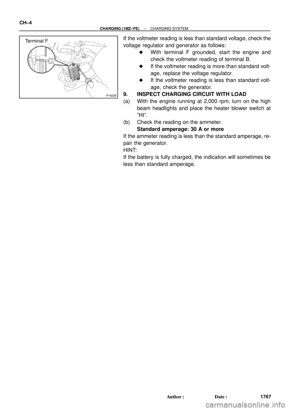
Terminal F CH±4
± CHARGING (1MZ±FE)CHARGING SYSTEM
1767 Author�: Date�:
If the voltmeter reading is less than standard voltage, check the
voltage regulator and generator as follows:
�With terminal F grounded, start the engine and
check the voltmeter reading of terminal B.
�If the voltmeter reading is more than standard volt-
age, replace the voltage regulator.
�If the voltmeter reading is less than standard volt-
age, check the generator.
9. INSPECT CHARGING CIRCUIT WITH LOAD
(a) With the engine running at 2,000 rpm, turn on the high
beam headlights and place the heater blower switch at
ºHIº.
(b) Check the reading on the ammeter.
Standard amperage: 30 A or more
If the ammeter reading is less than the standard amperage, re-
pair the generator.
HINT:
If the battery is fully charged, the indication will sometimes be
less than standard amperage.
Page 2400 of 4770
RADIATOR
1626 Author�: Date�:
REMOVAL
HINT:
�At the time of installation, please refer to the following
items.
�Start the")
CO03O±03
S04725
B05937
Lower
Hose
Oil
Cooler
Hose
CO±18
± COOLING (1MZ±FE)RADIATOR
1626 Author�: Date�:
REMOVAL
HINT:
�At the time of installation, please refer to the following
items.
�Start the engine, and check for coolant and A/T fluid
leaks.
�Check the A/T fluid level. (See page DI±438)
1. DRAIN ENGINE COOLANT
2. CANADA:
DISCONNECT RELAY BLOCK (FOR DAYTIME
RUNNING LIGHT SYSTEM) FROM BATTERY
HOLD±DOWN CLAMP
3. DISCONNECT UPPER RADIATOR HOSE FROM
RADIATOR
4. DISCONNECT LOWER RADIATOR HOSE FROM
WATER INLET PIPE
5. DISCONNECT A/T OIL COOLER HOSES FROM OIL
COOLER PIPES
6. DISCONNECT NO.1 AND NO.2 COOLING FAN
CONNECTORS
7. DISCONNECT NO.1 ECT SWITCH WIRE CONNECTOR
8. REMOVE RADIATOR AND COOLING FANS
ASSEMBLY
(a) Remove the 2 bolts and 2 upper supports.
Torque: 12.8 N´m (130 kgf´cm, 9 ft´lbf)
(b) Lift out the radiator, and remove the radiator and cooling
fans assembly.
(c) Remove the 2 lower supports.
9. REMOVE A/T OIL COOLER HOSES FROM
RADIATOR
10. REMOVE LOWER RADIATOR HOSE FROM
RADIATOR
Page 2422 of 4770

DI00G±05
ENGINE CONTROL SYSTEM Check Sheet
Customer's Name
Driver's Name
Data Vehicle
Brought in
License No.
Model and Model
Year
Frame No.
Engine Model
Odometer Reading
Problem Symptoms
Engine does
not Start
Difficult to
Start
Poor Idling
Poor
Driveaability
Engine Stall
Others
Engine does not crankNo initial combustionNo complete combustion
Engine cranks slowly
Other
Incorrect first idleIdling rpm is abnormalHigh ( rpm)Low ( rpm)
Rough idling
Other
HesitationBack fireMuffler explosion (after±fire)Surging
Knocking
Other
Soon after startingAfter accelerator pedal depressed
After accelerator pedal released
During A/C operation
Shifting from N to D
Other
Datas Problem
Occurred
Problem Frequency
Condition When
Problem Occurs
Weather
Engine Operation
Engine Temperature Place Outdoor
TemperatureConstant
Sometimes ( times per day/month)Once only
Other
Fine
CloudyRainySnowyVarious/Other
Hot
Warm CoolCold (approx. °F/ °C)
Highway
SuburbsInner cityUphillDownhill
Rough road
Other
Cold
Warming upAfter warming upAny temperatureOther
Starting
Just after starting ( min.)IdlingRacing
Driving
Constant speedAccelerationDeceleration
A/C switch ON/OFF
Other
Condition of MILRemains on Sometimes light up Does not light up
NormalMalfunction code(s) (code )
Freezed frame data ( )
NormalMalfunction code(s) (code )
Freezed frame data ( )
Normal Mode
(Precheck)
Check Mode DTC InspectionInspector's
Name
km
miles
DI±2
± DIAGNOSTICSENGINE (5S±FE)
237 Author�: Date�:
CUSTOMER PROBLEM ANALYSIS CHECK
Page 2423 of 4770

DI±3
238 Author�: Date�:
PRE±CHECK
1. DIAGNOSIS SYSTEM
(a) Description
�When troubleshooting OBD II vehicles, the")
DI00H±08
FI0534
S05331
TOYOTA Hand±Held Tester
DLC3
± DIAGNOSTICSENGINE (5S±FE)
DI±3
238 Author�: Date�:
PRE±CHECK
1. DIAGNOSIS SYSTEM
(a) Description
�When troubleshooting OBD II vehicles, the only dif-
ference from the usual troubleshooting procedure
is that you connect to the vehicle the OBD II scan
tool complying with SAE J1978 or TOYOTA hand±
held tester, and read off various data output from
the vehicle's ECM.
�OBD II regulations require that the vehicle's on±
board computer lights up the Malfunction Indicator
Lamp (MIL) on the instrument panel when the com-
puter detects a malfunction in the emission control
system / components or in the powertrain control
components which affect vehicle emissions, or a
malfunction in the computer. In addition to the MIL
lighting up when a malfunction is detected, the ap-
plicable Diagnostic Trouble Code (DTC) prescribed
by SAE J2012 are recorded in the ECM memory.
(See page DI±16)
If the malfunction does not reoccur in 3 consecutive trips, the
MIL goes off automarially but the DTCs remain recorded in the
ECM memory.
�To check the DTCs, connect the OBD II scan tool or
TOYOTA hand±held tester to Data Link Connector
3 (DLC3) on the vehicle. The OBD II scan tool or
TOYOTA hand±held tester also enables you to
erase the DTCs and check freezed frame data and
various forms of engine data (For operating instruc-
tions, see the OBD II scan tool's instruction book.)
DTCs include SAE controlled codes and manufac-
turer controlled codes. SAE controlled codes must
be set as prescribed by the SAE, while manufactur-
er controlled codes can be set freely by the
manufacturer within the prescribed limits. (See DTC
chart on page DI±16)