Page 2537 of 4770
(c)
(d)
(b)
FI6514
OX Signal Waveform (Oscilloscope)
1.0 V
0 V
200 msec. /Division
± DIAGNOSTICSENGINE (5S±F")
FI7132
Engine Speed
2,500 ~ 3,000 rpm
Idling
IG SW OFF
Warmed up3 min. or soCheck
Time (a)(c)
(d)
(b)
FI6514
OX Signal Waveform (Oscilloscope)
1.0 V
0 V
200 msec. /Division
± DIAGNOSTICSENGINE (5S±FE)
DI±117
352 Author�: Date�:
CONFIRMATION ENGINE RACING PATTERN
(a) Connect the TOYOTA hand±held tester to the DLC3, or connect the probe of the oscilloscope between
terminals OX1, OX2 and E1 of the ECM connector.
(b) Start engine and warm it up with all accessories switched OFF until water temp. is stable.
(c) Race the engine at 2,500 ~ 3,000 rpm for about 3 min.
(d) After confirming that the waveforms of the heated oxygen sensor (bank 1 sensor 1 (OX1)), oscillate
around 0.5 V during feedback to the ECM, check the waveform of the heated oxygen sensor (bank
1 sensor 2 (OX2)).
HINT:
�If there is a malfunction in the system, the waveform of the
heated oxygen sensor (bank 1 sensor 2 (OX2)) is almost
the same as that of the heated oxygen sensor (bank 1
sensor 1 (OX1)) on the left.
�There are some cases where, even though a malfunction
exists, the MIL may either light up or not light up.
Page 2573 of 4770

Idling
IG SW OFF
3 ~ 5 min.
Time
(1)(2)(4)
(3)
± DIAGNOSTICSENGINE (5S±FE)
DI±153
388 Author�: Date�:
CONFIRMATION DRIVING PATTERN
(1) Connect the")
A00364
Vehicle Speed
60 ~ 120 km/h
(38 ~ 75 mph)
Idling
IG SW OFF
3 ~ 5 min.
Time
(1)(2)(4)
(3)
± DIAGNOSTICSENGINE (5S±FE)
DI±153
388 Author�: Date�:
CONFIRMATION DRIVING PATTERN
(1) Connect the TOYOTA hand±held tester to the DLC3.
(2) Switch the TOYOTA hand±held tester from normal mode to check mode (See page DI±3).
(3) Start the engine and warm it up with all accessory switches OFF.
(4) Drive the vehicle at 60 ~ 120 km/h (38 ~ 75 mph) and engine speed at 1,600 ~ 3,200 rpm for 3
~ 5 min.
HINT:
If a malfunction exists, the MIL will light up during step (4).
NOTICE:
If the conditions in this test are not strictly followed, detection of the malfunction will not be possible.
If you do not have a TOYOTA hand±held tester, turn the ignition switch OFF after performing steps
(3) and (4), then perform steps (3) and (4) again.
INSPECTION PROCEDURE
HINT:
Read freeze frame data using TOYOTA hand±held tester or OBD II scan tool. Because freeze frame records
the engine conditions when the malfunction is detected, when troubleshooting it is useful for determining
whether the vehicle was running or stopped, the engine warmed up or not, the air±fuel ratio lean or rich, etc.
at the time of the malfunction.
1 Are there any other codes (besides DTC P1130) being output?
YES Go to relevant DTC chart.
NO
Page 2591 of 4770
± DIAGNOSTICSENGINE (5S±FE)
DI±171
406 Author�: Date�:
INSPECTION PROCEDURE
HINT:
Read freeze frame data using TOYOTA hand±held tester or OBD II scan tool. Because freeze frame records
the engine conditions when the malfunction is detected, when troubleshooting it is useful for determining
whether the vehicle was running or stopped, the engine warmed up or not, the air±fuel ratio lean or rich, etc.
at the time of the malfunction.
1 Check operation of stop light.
PREPARATION:
Check if the stop lights go on and off normally when the brake pedal is operated and released.
NG Check and repair stop light circuit
(See page BE±37).
OK
Page 2592 of 4770
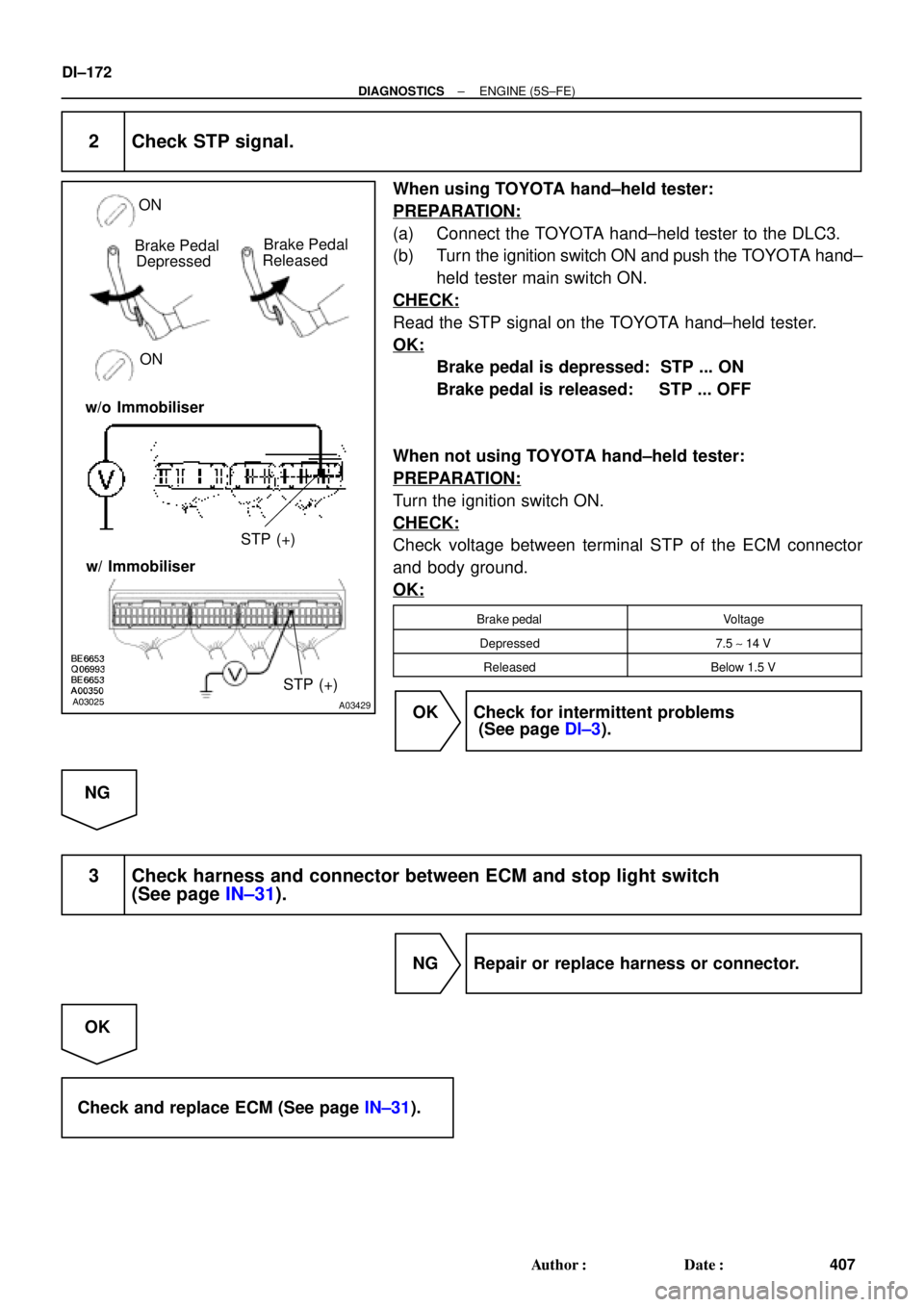
A03025A03429
Brake Pedal
Depressed
ON ON
STP (+) Brake Pedal
Released
w/o Immobiliser
w/ Immobiliser
STP (+)
DI±172
± DIAGNOSTICSENGINE (5S±FE)
407 Author�: Date�:
2 Check STP signal.
When using TOYOTA hand±held tester:
PREPARATION:
(a) Connect the TOYOTA hand±held tester to the DLC3.
(b) Turn the ignition switch ON and push the TOYOTA hand±
held tester main switch ON.
CHECK:
Read the STP signal on the TOYOTA hand±held tester.
OK:
Brake pedal is depressed: STP ... ON
Brake pedal is released: STP ... OFF
When not using TOYOTA hand±held tester:
PREPARATION:
Turn the ignition switch ON.
CHECK:
Check voltage between terminal STP of the ECM connector
and body ground.
OK:
Brake pedalVoltage
Depressed7.5 ~ 14 V
ReleasedBelow 1.5 V
OK Check for intermittent problems
(See page DI±3).
NG
3 Check harness and connector between ECM and stop light switch
(See page IN±31).
NG Repair or replace harness or connector.
OK
Check and replace ECM (See page IN±31).
Page 2616 of 4770

DI079±02
ENGINE CONTROL SYSTEM Check Sheet
Customer's Name
Driver's Name
Date Vehicle
Brought in
License No.
Model and Model
Year
Frame No.
Engine Model
Odometer Reading
Problem Symptoms
Engine does
not Start
Difficult to
Start
Poor Idling
Poor
Driveability
Engine Stall
Others
Engine does not crankNo initial combustionNo complete combustion
Engine cranks slowly
Other
Incorrect first idleIdling rpm is abnormalHigh ( rpm)Low ( rpm)
Rough idling
Other
HesitationBack fireMuffler explosion (after±fire)Surging
Knocking
Other
Soon after startingAfter accelerator pedal depressed
After accelerator pedal released
During A/C operation
Shifting from N to D
Other
Dates Problem
Occurred
Problem Frequency
Condition When
Problem Occurs
Weather
Engine Operation
Engine Temperature Place Outdoor
TemperatureConstant
Sometimes ( times per day/month)Once only
Other
Fine
CloudyRainySnowyVarious/Other
Hot
Warm CoolCold (approx. °F/ °C)
Highway
SuburbsInner cityUphillDownhill
Rough road
Other
Cold
Warming upAfter warming upAny temperatureOther
Starting
Just after starting ( min.)IdlingRacing
Driving
Constant speedAccelerationDeceleration
A/C switch ON/OFF
Other
Condition of MILRemains on Sometimes light up Does not light up
NormalMalfunction code(s) (code )
Freezed frame data ( )
NormalMalfunction code(s) (code )
Freezed frame data ( )
Normal Mode
(Precheck)
Check Mode DTC InspectionInspector's
Name
km
miles
DI±196
± DIAGNOSTICSENGINE (1MZ±FE)
431 Author�: Date�:
CUSTOMER PROBLEM ANALYSIS CHECK
Page 2617 of 4770

DI±197
432 Author�: Date�:
PRE±CHECK
1. DIAGNOSIS SYSTEM
(a) Description
�When troubleshooting OBD II vehicles, the on")
DI07A±06
FI0534
A06134
TOYOTA Hand±Held Tester
± DIAGNOSTICSENGINE (1MZ±FE)
DI±197
432 Author�: Date�:
PRE±CHECK
1. DIAGNOSIS SYSTEM
(a) Description
�When troubleshooting OBD II vehicles, the only dif-
ference from the usual troubleshooting procedure
is that you connect to the vehicle the OBD II scan
tool complying with SAE J1978 or TOYOTA hand±
held tester, and read off various data output from
the vehicle's ECM.
�OBD II regulations require that the vehicle's on±
board computer lights up the Malfunction Indicator
Lamp (MIL) on the instrument panel when the com-
puter detects a malfunction in the emission control
system/components or in the powertrain control
components which affect vehicle emissions, or a
malfunction in the computer. In addition to the MIL
lighting up when a malfunction is detected, the ap-
plicable Diagnostic Trouble Codes (DTC) pre-
scribed by SAE J2012 are recorded in the ECM
memory (See page DI±211).
If the malfunction does not reoccur in 3 consecutive trips, the
MIL goes off but the DTCs remain recorded in the ECM memory.
�To check the DTC, connect the OBD II scan tool or
TOYOTA hand±held tester to Data Link Connector
3 (DLC3) on the vehicle. The OBD II scan tool or
TOYOTA hand±held tester also enables you to
erase the DTC and check freezed frame data and
various forms of engine data (For operating instruc-
tions, see the OBD II scan tool's instruction book.).
DTC include SAE controlled codes and manufac-
turer controlled codes. SAE controlled codes must
be set as prescribed by the SAE, while manufactur-
er controlled codes can be set freely by the
manufacturer within the prescribed limits (See DTC
chart on page DI±211).
Page 2618 of 4770

433 Author�: Date�: �
The diagnosis system operates in normal mode
during normal vehicle use. It also has a check mode
for technicians to simulate malfunction sy")
DI±198
± DIAGNOSTICSENGINE (1MZ±FE)
433 Author�: Date�: �
The diagnosis system operates in normal mode
during normal vehicle use. It also has a check mode
for technicians to simulate malfunction symptoms
and troubleshoot. Most DTC use 2 trip detection
logic* to prevent erroneous detection, and ensure
thorough malfunction detection. By switching the
ECM to check mode when troubleshooting, the
technician can cause the MIL to light up for a mal-
function that is only detected once or momentarily
(TOYOTA hand±held tester only). (See page
DI±197)
�*2 trip detection logic:
When a malfunction is first detected, the malfunc-
tion is temporarily stored in the ECM memory. (1st
trip)
If the same malfunction is detected again during the second
drive test, this second detection causes the MIL to light up. (2nd
trip) (However, the IG switch must be turned OFF between the
1st trip and the 2nd trip.).
�Freeze frame data:
Freeze frame data records the engine condition
when a misfire (DTCs P0300 ~ P0306) or fuel trim
malfunction (DTCs P0171, P0172) or other mal-
function (first malfunction only), is detected.
Because freeze frame data records the engine
conditions (fuel system, calculated load, engine
coolant temperature, fuel trim, engine speed, ve-
hicle speed, etc.) when the malfunction is detected,
when troubleshooting it is useful for determining
whether the vehicle was running or stopped, the en-
gine warmed up or not, the air±fuel ratio lean or rich,
etc. at the time of the malfunction.
�Priorities for troubleshooting:
If troubleshooting priorities for multiple DTC are given in the ap-
plicable DTC chart, these should be followed.
If no instructions are given troubleshoot DTC according to the
following priorities.
(1) DTC other than fuel trim malfunction (DTCs P0171,
P0172), EGR (DTCs P0401, P0402) and misfire
(DTCs P0300 ~ P0306).
(2) Fuel trim malfunction (DTCs P0171, P0172) and
EGR (DTCs P0401, P0402).
(3) Misfire (DTCs P0300 ~ P0306).
Page 2619 of 4770

DI±199
434 Author�: Date�:
(b) Check the DLC3.
The vehicles ECM uses ISO 9141±2 for communication.
The terminal arrangement of DLC3 complies with S")
N09214
DLC3
S04159
± DIAGNOSTICSENGINE (1MZ±FE)
DI±199
434 Author�: Date�:
(b) Check the DLC3.
The vehicle's ECM uses ISO 9141±2 for communication.
The terminal arrangement of DLC3 complies with SAE
J1962 and matches the ISO 9141±2 format.
Terminal No.Connection / Voltage or ResistanceCondition
7Bus � Line / Pulse generationDuring transmission
4Chassis Ground e Body Ground /1 W or lessAlways
5Signal Ground e Body Ground /1 W or lessAlways
16Battery Positive e Body Ground /9 ~ 14 VAlways
HINT:
If your display shows ºUNABLE TO CONNECT TO VEHICLEº
when you have connected the cable of the OBD II scan tool or
TOYOTA hand±held tester to DLC3, turned the ignition switch
ON and operated the scan tool, there is a problem on the ve-
hicle side or tool side.
�If communication is normal when the tool is connected to
another vehicle, inspect DLC3 on the original vehicle.
�If communication is still not possible when the tool is con-
nected to another vehicle, the problem is probably in the
tool itself, so consult the Service Department listed in the
tool's instruction manual.
2. INSPECT DIAGNOSIS (Normal Mode)
(a) Check the MIL.
(1) The MIL comes on when the ignition switch is turned
ON and the engine is not running.
HINT:
If the MIL does not light up, troubleshoot the combination meter
(See page BE±46).
(2) When the engine started, the MIL should go off. If
the lamp remains on, the diagnosis system has de-
tected a malfunction or abnormality in the system.
(b) Check the DTC.
NOTICE:
TOYOTA hand±held tester only: When the diagnosis sys-
tem is switched from normal mode to check mode, it erases
all DTC and freezed frame data recorded in normal mode.
So before switching modes, always check the DTC and
freezed frame data, and note them down.
(1) Prepare the OBD II scan tool (complying with SAE
J1978) or TOYOTA hand±held tester.