EM04K±04
P18805
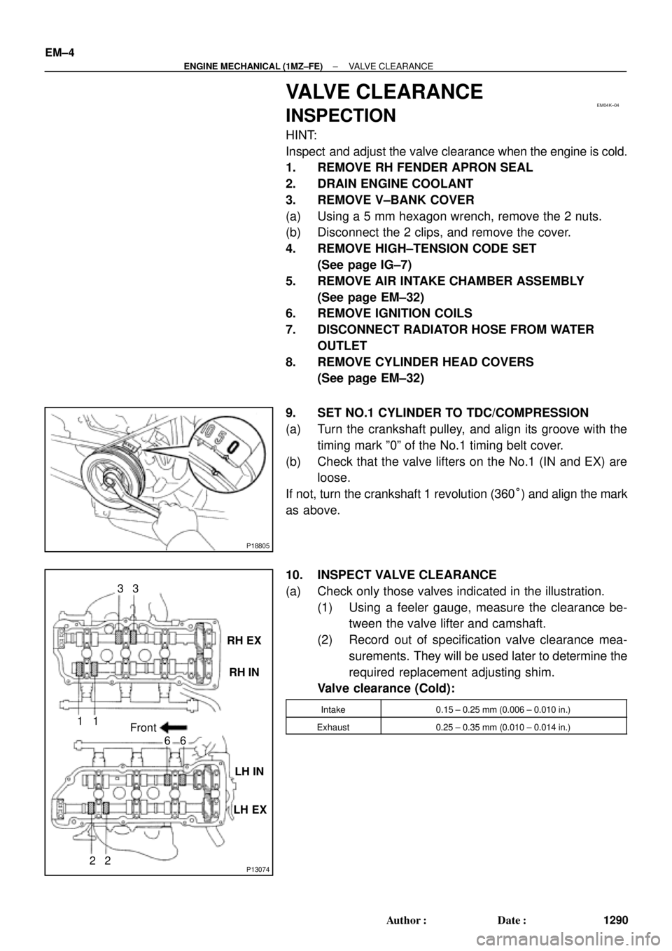
P13074
RH EX
RH IN
LH IN
LH EX 13
6
23
1
6
2Front EM±4
± ENGINE MECHANICAL (1MZ±FE)VALVE CLEARANCE
1290 Author�: Date�:
VALVE CLEARANCE
INSPECTION
HINT:
Inspect and adjust the valve clearance when the engine is cold.
1. REMOVE RH FENDER APRON SEAL
2. DRAIN ENGINE COOLANT
3. REMOVE V±BANK COVER
(a) Using a 5 mm hexagon wrench, remove the 2 nuts.
(b) Disconnect the 2 clips, and remove the cover.
4. REMOVE HIGH±TENSION CODE SET
(See page IG±7)
5. REMOVE AIR INTAKE CHAMBER ASSEMBLY
(See page EM±32)
6. REMOVE IGNITION COILS
7. DISCONNECT RADIATOR HOSE FROM WATER
OUTLET
8. REMOVE CYLINDER HEAD COVERS
(See page EM±32)
9. SET NO.1 CYLINDER TO TDC/COMPRESSION
(a) Turn the crankshaft pulley, and align its groove with the
timing mark º0º of the No.1 timing belt cover.
(b) Check that the valve lifters on the No.1 (IN and EX) are
loose.
If not, turn the crankshaft 1 revolution (360°) and align the mark
as above.
10. INSPECT VALVE CLEARANCE
(a) Check only those valves indicated in the illustration.
(1) Using a feeler gauge, measure the clearance be-
tween the valve lifter and camshaft.
(2) Record out of specification valve clearance mea-
surements. They will be used later to determine the
required replacement adjusting shim.
Valve clearance (Cold):
Intake0.15 ± 0.25 mm (0.006 ± 0.010 in.)
Exhaust0.25 ± 0.35 mm (0.010 ± 0.014 in.)
PP0JS±04
PP±6
± PREPARATIONENGINE MECHANICAL (5S±FE)
58 Author�: Date�:
EQUIPMENT
Abrasive compoundValve
Caliper gauge
CO/HC meter
Compression gauge
Connecting aligner
Cylinder gauge
Dial indicator
Dye penetrant
Engine tune±up tester
Groove cleaning toolPiston ring groove
Heater
Magnetic finger
Micrometer
OBDII scan tool
Pin hole grinderPiston pin hole of piston
Piston ring compressor
Piston ring expander
Plastigage
Precision straight edge
Press
Ridge reamerCylinder
Soft brush
Solvent
Spring testerValve spring
Steel squareValve spring
Thermometer
Torque wrench
Valve seat cutter
V±block
Vernier calipers
Wire brushValve