Page 3615 of 4770
CYLINDER BLOCK
EM±109
1395 Author�: Date�: �
Using a non±residue solvent, clean both sealing
surfaces.
(")
P12909
Seal Width 3 ± 5 mm
Z14261
1
23
45 6
7
89
10
P12389
SST
± ENGINE MECHANICAL (1MZ±FE)CYLINDER BLOCK
EM±109
1395 Author�: Date�: �
Using a non±residue solvent, clean both sealing
surfaces.
(b) Apply seal packing to the water inlet housing as shown in
the illustration.
Seal packing: Part No. 08826±00100 or equivalent
�Install a nozzle that has been cut to a 3 ± 5 mm (0.12
± 0.20 in.) opening.
HINT:
Avoid applying an excessive amount to the surface.
�Parts must be assembled within 3 minutes of ap-
plication. Otherwise the material must be removed
and reapplied.
�Immediately remove nozzle from the tube and rein-
stall cap.
(c) Install the water inlet housing with the 8 bolts and 2 nuts.
Uniformly tighten the bolts and nuts, in several passes, in
the sequence shown.
Torque: 8 N´m (80 kgf´cm, 69 in.´lbf)
(d) Install the engine wire band.
(e) Install the engine wire clamp.
27. INSTALL KNOCK SENSORS
(a) Using SST, install the 2 knock sensors.
SST 09816±30010
Torque: 39 N´m (400 kgf´cm, 29 ft´lbf)
(b) Connect the 2 knock sensor connectors.
28. INSTALL NO.2 IDLER PULLEY BRACKET
Torque: 28 N´m (290 kgf´cm, 21 ft´lbf)
29. INSTALL A/C COMPRESSOR HOUSING BRACKET
Torque: 25 N´m (250 kgf´cm, 18 ft´lbf)
Page 3700 of 4770

V08423 Knock Sensor 1
GRECM
KNK
E1 12
E6
WIRING DIAGRAM
Wiring Diagram
This shows a wiring diagram of the circuit.
Use this diagram together with ELECTRICAL
WIRING DIAGRAM to thoroughly understand the
circuit.
Wire colors are indicated by an alphabetical code.
B = Black, L = Blue, R = Red, BR = Brown,
LG = Light Green, V = Violet, G = Green,
O = Orange, W = White, GR = Gray, P = Pink,
Y = Yellow, SB = Sky Blue
The first letter indicates the basic wire color and
the second letter indicates the color of the stripe.
DTC P0325Knock Sensor 1 Circuit Malfunction
CIRCUIT DESCRIPTION
Knock sensor is fitted to the cylinder block to detect engine knocking. This sensor contains a piezoelectric element which
generates a voltage when it becomes deformed, which occurs when the cylinder block vibrates due to knocking. If engine
knocking occurs, ignition timing is retarded to suppress it.
DTC No. DTC Detecting Condition Trouble Area
P0325No knock sensor 1 signal to ECM with engine speed,
1,200 rpm or more.� Open or short in knock sensor1 circuit
� Knock sensor 1 (looseness)
� ECM
If the ECM detects the above diagnosis conditions, it operates the fall safe function in which the corrective retard angle
value is set to the maximum value.
� Diagnostic Trouble Code No. and Detection Item
� Circuit Description
The major role and operation, etc. of the circuit
and its component parts are explained.
� Indicates the diagnostic trouble code, diagnostic
trouble code set parameter and suspect area of
the problem.
�
± INTRODUCTIONHOW TO TROUBLESHOOT ECU CONTROLLED
SYSTEMSIN±29
29 Author�: Date�:
6. CIRCUIT INSPECTION
How to read and use each page is shown below.
Page 3701 of 4770
 Remove the glove compartment (See page SF±68).
(b) Disconnect the E6 connector of ECM.
INSPECTION PROCEDURE
Replace knock sensor. 1 Check continuity between terminal")
V08425
LOCK
KNK
E6 Connector
(a) Remove the glove compartment (See page SF±68).
(b) Disconnect the E6 connector of ECM.
INSPECTION PROCEDURE
Replace knock sensor. 1 Check continuity between terminal KNK of ECM connector and body ground.
OK:
Check knock sensor (See page SF±61).Measure resistance between terminal KNK of ECM connector
and body ground.
Resistance: 1 MW or higher
Connector being checked is connected. � Indicates the condition of the connector of ECU during the check.
PREPARATION:
CHECK:
2Go to step 3.
OK OK
NG
� Indicates the position of the ignition switch during the check.
Check from the connector back side.
(with harness)
Ignition Switch LOCK (OFF)
Ignition Switch START
LOCKIgnition Switch ON
Ignition Switch ACC
STARTON
ACC
�
� Indicates the place to check the voltage or resistance.
� Indicates the connector position to checked, from the front or back side.
Connector being checked is disconnected. Check from the connector front side. (without harness)
In this case, care must be taken not to bend the terminals.
E6 Connector KNKWire Harness
E6 Connector KNK
A00255 AB0117
A00265
Inspection Procedure
Use the inspection procedure to determine if
the circuit is normal or abnormal, and, if it is
abnormal, use it to determine whether the
problem is located in the sensors, actuators,
wire harness or ECU. IN±30
± INTRODUCTIONHOW TO TROUBLESHOOT ECU CONTROLLED
SYSTEMS
30 Author�: Date�:
Page 3713 of 4770

IACIdle Air ControlIdle Speed Control (ISC)
IATIntake Air TemperatureIntake or Inlet Air Temperature")
IN±42
± INTRODUCTIONTERMS
42 Author�: Date�:
HO2SHeated Oxygen SensorHeated Oxygen Sensor (HO2S)
IACIdle Air ControlIdle Speed Control (ISC)
IATIntake Air TemperatureIntake or Inlet Air Temperature
ICMIgnition Control Module±
IFIIndirect Fuel InjectionIndirect Injection (IDL)
IFSInertia Fuel±Shutoff±
ISCIdle Speed Control±
KSKnock SensorKnock Sensor
MAFMass Air FlowAir Flow Meter
MAPManifold Absolute PressureManifold Pressure
Intake Vacuum
MCMixture Control
Electric Bleed Air Control Valve (EBCV)
Mixture Control Valve (MCV)
Electric Air Control Valve (EACV)
MDPManifold Differential Pressure±
MFIMultiport Fuel InjectionElectronic Fuel Injection (EFI)
MILMalfunction Indicator LampCheck Engine Lamp
MSTManifold Surface Temperature±
MVZManifold Vacuum Zone±
NVRAMNon±Volatile Random Access Memory±
O2SOxygen SensorOxygen Sensor, O2 Sensor (O2S)
OBDOn±Board DiagnosticOn±Board Diagnostic System (OBD)
OCOxidation Catalytic ConverterOxidation Catalyst Convert (OC), CCo
OPOpen LoopOpen Loop
PAIRPulsed Secondary Air InjectionAir Suction (AS)
PCMPowertrain Control Module±
PNPPark/Neutral Position±
PROMProgrammable Read Only Memory±
PSPPower Steering Pressure±
PTOXPeriodic Trap OxidizerDiesel Particulate Filter (DPF)
Diesel Particulate Trap (DPT)
RAMRandom Access MemoryRandom Access Memory (RAM)
RMRelay Module±
ROMRead Only MemoryRead Only Memory (ROM)
RPMEngine SpeedEngine Speed
SCSuperchargerSupercharger
SCBSupercharger BypassE±ABV
SFISequential Multiport Fuel InjectionElectronic Fuel Injection (EFI), Sequential Injection
SPLSmoke Puff Limiter±
SRIService Reminder Indicator±
SRTSystem Readiness Test±
STScan Tool±
TBThrottle BodyThrottle Body
TBIThrottle Body Fuel InjectionSingle Point Injection
Central Fuel Injection (Ci)
TCTurbochargerTurbocharger
TCCTorque Converter ClutchTorque Converter
Page 3860 of 4770
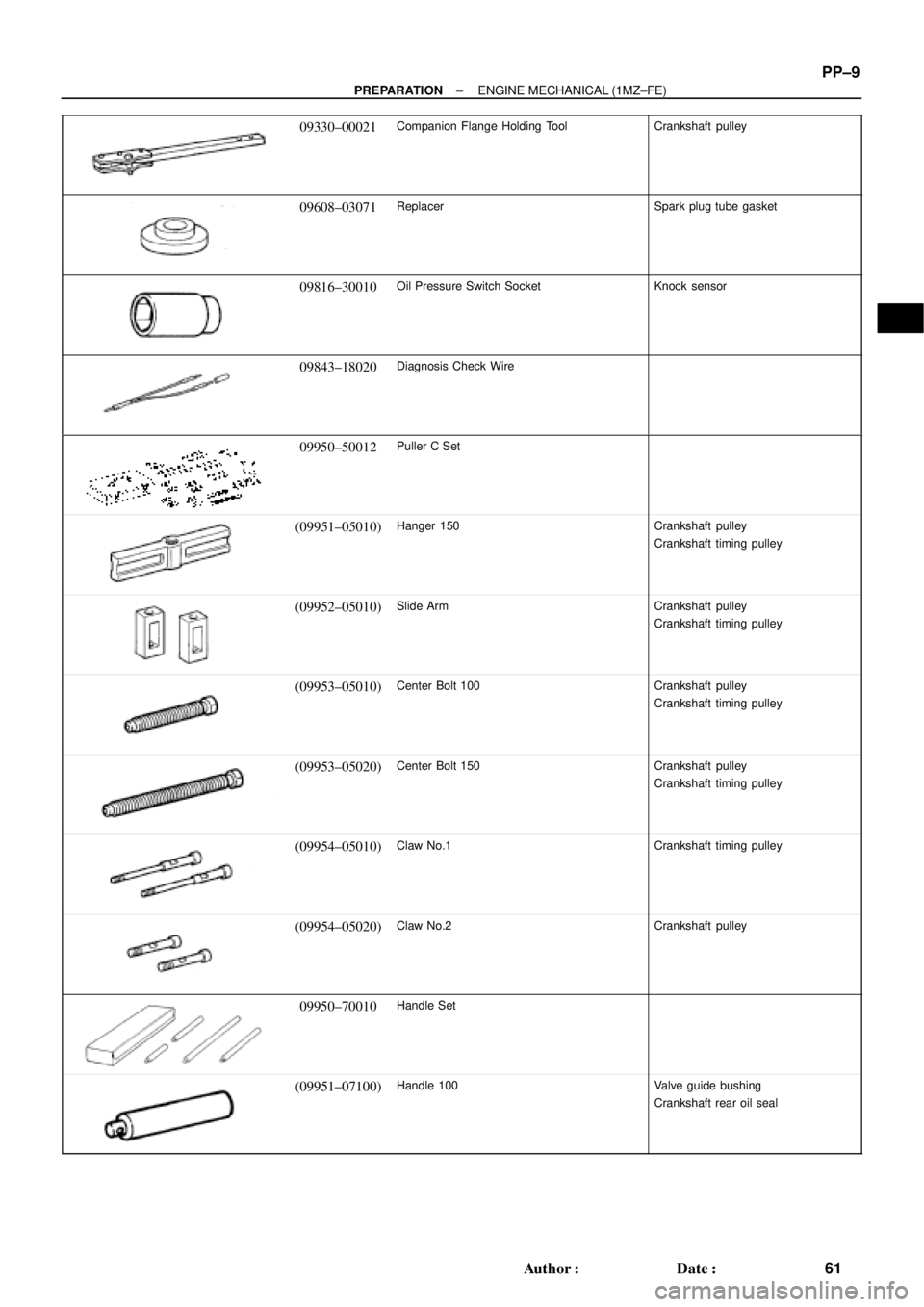
± PREPARATIONENGINE MECHANICAL (1MZ±FE)
PP±9
61 Author�: Date�:
09330±00021Companion Flange Holding ToolCrankshaft pulley
09608±03071ReplacerSpark plug tube gasket
09816±30010Oil Pressure Switch SocketKnock sensor
09843±18020Diagnosis Check Wire
09950±50012Puller C Set
(09951±05010)Hanger 150Crankshaft pulley
Crankshaft timing pulley
(09952±05010)Slide ArmCrankshaft pulley
Crankshaft timing pulley
(09953±05010)Center Bolt 100Crankshaft pulley
Crankshaft timing pulley
(09953±05020)Center Bolt 150Crankshaft pulley
Crankshaft timing pulley
(09954±05010)Claw No.1Crankshaft timing pulley
(09954±05020)Claw No.2Crankshaft pulley
09950±70010Handle Set
(09951±07100)Handle 100Valve guide bushing
Crankshaft rear oil seal
Page 3868 of 4770
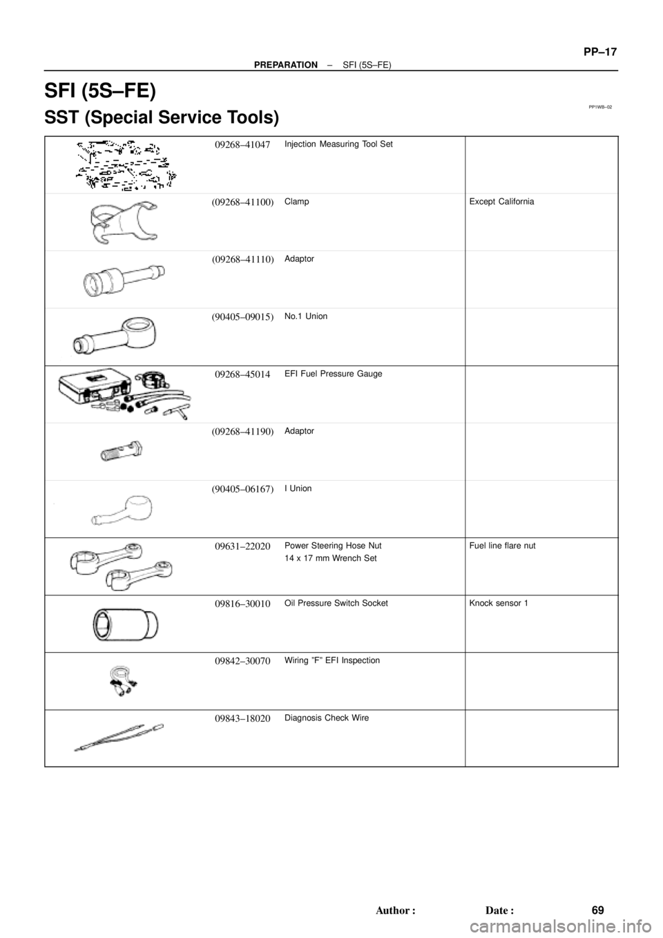
PP1WB±02
± PREPARATIONSFI (5S±FE)
PP±17
69 Author�: Date�:
SFI (5S±FE)
SST (Special Service Tools)
09268±41047Injection Measuring Tool Set
(09268±41100)ClampExcept California
(09268±41110)Adaptor
(90405±09015)No.1 Union
09268±45014EFI Fuel Pressure Gauge
(09268±41190)Adaptor
(90405±06167)I Union
09631±22020Power Steering Hose Nut
14 x 17 mm Wrench SetFuel line flare nut
09816±30010Oil Pressure Switch SocketKnock sensor 1
09842±30070Wiring ºFº EFI Inspection
09843±18020Diagnosis Check Wire
Page 3871 of 4770
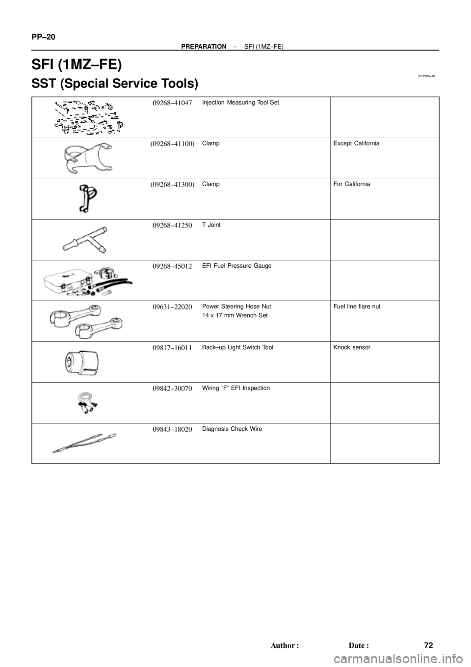
PP1WW±01
PP±20
± PREPARATIONSFI (1MZ±FE)
72 Author�: Date�:
SFI (1MZ±FE)
SST (Special Service Tools)
09268±41047Injection Measuring Tool Set
(09268±41100)ClampExcept California
(09268±41300)ClampFor California
09268±41250T Joint
09268±45012EFI Fuel Pressure Gauge
09631±22020Power Steering Hose Nut
14 x 17 mm Wrench SetFuel line flare nut
09817±16011Back±up Light Switch ToolKnock sensor
09842±30070Wiring ºFº EFI Inspection
09843±18020Diagnosis Check Wire
Page 3977 of 4770

SS±15
178 Author�: Date�:
No.2 RH engine mounting stay x No.2 Generator bracket6465047
RH engine mounting stay x Water outlet3232023
RH engine mou")
± SERVICE SPECIFICATIONSENGINE MECHANICAL (1MZ±FE)
SS±15
178 Author�: Date�:
No.2 RH engine mounting stay x No.2 Generator bracket6465047
RH engine mounting stay x Water outlet3232023
RH engine mounting stay x Engine moving control rod3232023
RH engine mounting stay x No.2 RH engine mounting bracket3232023
Front engine mounting insulator x Front frame
TMC made
TMMK made Silver color bolt
Green color bolt
80
44
66820
450
67059
32
48
Engine mounting absorber x Front frame4849035
Engine mounting absorber x Transaxle4849035
Rear engine mounting insulator x Front frame6667048
LH engine mounting insulator x Transaxle6465047
PS pump x PS pump bracket4344031
A/C compressor x Housing bracket2525018
A/C compressor x No.1 oil pan2525018
Generator adjusting bar x Drive belt adjusting bar bracket1818513
Main bearing cap x Cylinder block 12 pointed head bolt 1st
2nd
6 pointed head bolt22
Turn 90°
27225
Turn 90°
27516
Turn 90°
20
Connecting rod cap x Connecting rod 1st
2nd24.5
Turn 90°250
Turn 90°18
Turn 90°
Rear oil seal retainer x Cylinder block88069 in.´lbf
EGR cooler x Cylinder block99078 in.´lbf
Engine coolant drain union x Cylinder block3940029
Water seal plate x Cylinder block1818013
Oil filter union x Cylinder block3031022
Water inlet housing x Cylinder block88069 in.´lbf
Knock sensor x Cylinder block3940029
No.2 idler pulley bracket x Cylinder block2829021
A/C compressor housing bracket x Cylinder block2525018
Generator bracket x Cylinder block4344032
Drive plate x Crankshaft8385061
Flywheel x Crankshaft8385061
Front exhaust pipe support bracket x No.1 oil pan2121015
Front exhaust pipe x Exhaust manifold6263046
Front exhaust pipe x Center exhaust pipe5657041
Center exhaust pipe x Tailpipe5657041
Front exhaust pipe bracket x Sub frame3333024
Front exhaust pipe support bracket x Front exhaust pipe stay3333024
Heated oxygen sensor x Center exhaust pipe4445033