Page 2637 of 4770
DI07C±06
A07469
Engine Coolant
Temp. Sensor
Heated Oxygen Sensor
(Bank 1 Sensor 2) VSV for EVAP VSV for ACIS
Crankshaft Position
Sensor
Camshaft Position
Sensor
Heated Oxygen Sensor *1
(Bank 1 Sensor 1)
A/F Sensor*2
(Bank 1 Sensor 1)Park/Neutral Position Switch
Knock Sensor 1 Knock Sensor 2
EGR Gas Temp. Sensor InjectorDLC1ECMVSV for EGR
IAC ValveMass Air Flow MeterIgniter
*1 : Except California Specification vehicles
*2 : Only for California Specification vehiclesVapor Pressure
Sensor
DLC3
Heated Oxygen Sensor *1
(Bank 2 Sensor 1)
A/F Sensor*2
(Bank 2 Sensor 1)
Canister
EGR Valve
Position Sensor
± DIAGNOSTICSENGINE (1MZ±FE)
DI±217
452 Author�: Date�:
PARTS LOCATION
Page 2703 of 4770

Knock Sensor 2
(On left bank)EC1 1W
W1
2W
WECM
KNKR
KNKLE1
E1 EC1 1E11
E112827
± DIAGNOSTICSENGINE (1MZ±FE)
DI±283
518 Author�: Date�:
DTC P0325 Knock Sensor 1")
A03315
Knock Sensor 1
(On right bank)
Knock Sensor 2
(On left bank)EC1 1W
W1
2W
WECM
KNKR
KNKLE1
E1 EC1 1E11
E112827
± DIAGNOSTICSENGINE (1MZ±FE)
DI±283
518 Author�: Date�:
DTC P0325 Knock Sensor 1 Circuit Malfunction
DTC P0330 Knock Sensor 2 Circuit Malfunction
CIRCUIT DESCRIPTION
Knock sensors are fitted one to the right bank and left bank of the cylinder block to detect engine knocking.
This sensor contains a piezoelectric element which generates a voltage when it becomes deformed, which
occurs when the cylinder block vibrates due to knocking. If engine knocking occurs, ignition timing is retarded
to suppress it.
DTC No.DTC Detecting ConditionTrouble Area
P0325No knock sensor 1 signal to ECM with engine speed between
2,000 rpm and 5,600 rpm.�Open or short in knock sensor 1 circuit
�Knock sensor 1 (looseness)
�ECM
P0330No knock sensor 2 signal to ECM with engine speed between
2,000 rpm and 5,600 rpm.�Open or short in knock sensor 2 circuit
�Knock sensor 2 (looseness)
�ECM
If the ECM detects the above diagnosis conditions, it operates the fail±safe function in which the corrective
retard angle value is set to the maximum value.
WIRING DIAGRAM
DI07T±06
Page 2704 of 4770

519 Author�: Date�:
INSPECTION PROCEDURE
HINT:
�DTC P0325 is for the")
A00304
Knock SensorECM
EC1
Male
ConnectorFemale
Connector 1
1
11
22KNKR
KNKL
EC1
E6
E627
28
DI±284
± DIAGNOSTICSENGINE (1MZ±FE)
519 Author�: Date�:
INSPECTION PROCEDURE
HINT:
�DTC P0325 is for the right bank knock sensor circuit. DTC P0330 is for the left bank knock sensor cir-
cuit.
�Read freeze frame data using TOYOTA hand±held tester or OBD II scan tool. Because freeze frame
records the engine conditions when the malfunction is detected, when troubleshooting it is useful for
determining whether the vehicle was running or stopped, the engine warmed up or not, the air±fuel
ratio lean or rich, etc. at the time of the malfunction.
1 Connect OBD II scan tool or TOYOTA hand±held tester, and check knock sensor
circuit.
PREPARATION:
(a) Connect the OBD II scan tool or TOYOTA hand±held tes-
ter to the DLC3.
(b) Disconnect the wire to wire connector EC1.
(c) Connect the terminals of the disconnected EC1 male con-
nector and EC1 female as follows.
Male connector eFemale connector
Terminal 1 e Terminal 2
Terminal 2 e Terminal 1
(d) Turn the ignition switch ON and push the OBD II scan tool
or TOYOTA hand±held tester main switch ON.
(e) After the engine is warmed up, perform quick racing to
4,000 rpm three times.
CHECK:
Check the DTC.
RESULT:
Type IDTC same as when vehicle brought in.
P0325 " P0325 or P0330 " P0330
Type IIDTC different to when vehicle brought in.
P0325 " P0330 or P0330 " P0325
Page 2705 of 4770
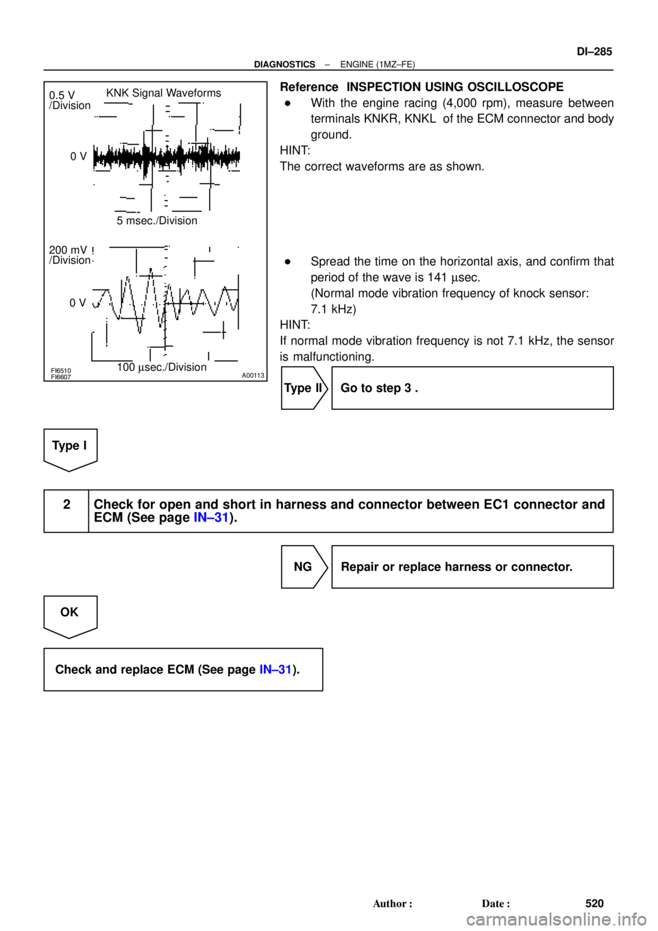
FI6510FI6607A00113
KNK Signal Waveforms
0.5 V
/Division
5 msec./Division
100 msec./Division 0 V
200 mV
/Division
0 V
± DIAGNOSTICSENGINE (1MZ±FE)
DI±285
520 Author�: Date�:
Reference INSPECTION USING OSCILLOSCOPE
�With the engine racing (4,000 rpm), measure between
terminals KNKR, KNKL of the ECM connector and body
ground.
HINT:
The correct waveforms are as shown.
�Spread the time on the horizontal axis, and confirm that
period of the wave is 141 msec.
(Normal mode vibration frequency of knock sensor:
7.1 kHz)
HINT:
If normal mode vibration frequency is not 7.1 kHz, the sensor
is malfunctioning.
Type II Go to step 3 .
Type I
2 Check for open and short in harness and connector between EC1 connector and
ECM (See page IN±31).
NG Repair or replace harness or connector.
OK
Check and replace ECM (See page IN±31).
Page 2706 of 4770
DI±286
± DIAGNOSTICSENGINE (1MZ±FE)
521 Author�: Date�:
3 Check for open and short in harness and connector between EC1 connector and
knock sensor (See page IN±31).
HINT:
�If DTC P0325 has changed to P0330, check the knock sensor circuit on the right bank side.
�If DTC P0330 has changed to P0325, check the knock sensor circuit on the left bank side.
NG Repair or replace harness or connector.
OK
Replace knock sensor.
Page 3417 of 4770
TIMING BELT
EM±25
1197 Author�: Date�:
(b) Install the timing belt cover with the 4 bolts.
(c) Install the")
A02591
S05588
SSTSST
S05592
SST
SST
Fulcrum
Length
S05587
Turn
± ENGINE MECHANICAL (5S±FE)TIMING BELT
EM±25
1197 Author�: Date�:
(b) Install the timing belt cover with the 4 bolts.
(c) Install the clamp of the crankshaft position sensor wire to
the timing belt cover.
(d) Install the crankshaft position sensor wire to the clamp on
the timing belt cover.
8. INSTALL CRANKSHAFT PULLEY
(a) Align the pulley set key with the key groove of the pulley,
and slide on the pulley.
(b) Using SST (and bolt), install the pulley bolt.
SST 09213±54015 (91651±60855),09330±00021
Torque: 108 N´m (1,100 kgf´cm, 80 ft´lbf)
HINT:
Either of 2 types of pulley may be used, each with its own bolt
size, type A (91651±60855) and type B
(part No. 91121±40665).
9. INSTALL CAMSHAFT TIMING PULLEY
(a) Align the camshaft knock pin with the knock pin groove of
the pulley, and slide on the timing pulley.
(b) Using SST, install the pulley bolt.
SST 09249±63010, 09960±10010 (09962±01000,
09963±01000)
Torque:
54 N´m (550 kgf´cm, 40 ft´lbf)
37 N´m (380 kgf´cm, 27 ft´lbf) for use with SST
HINT:
Use a torque wrench with a fulcrum length of 340 mm (13.39
in.).
10. SET NO.1 CYLINDER TO TDC/COMPRESSION
(a) Turn the crankshaft pulley, and align its groove with timing
mark º0º of the No.1 timing belt cover.
Page 3423 of 4770
A07358
Ground Wire
MAP Sensor
Vacuum Hose
Brake Booster
Vacuum Hose
Intake
Manifold
Air Hose for Air Assist System (California)
Intake Manifold
Stay
Injector
(Except California)
Knock Sensor 1
ConnectorPCV HoseVSV Connector
for EGR
VSV for EGREGR Valve and Vacuum
Modulator
Fuel Inlet Hose
Fuel Pulsation Damper
� O±Ring
Injector
(California)Injector
Connector Spacer
Insulator
N´m (kgf´cm, ft´lbf)
� Non±reusable part
� Gasket
� Insulator� Grommet
� O±Ring � Gasket� Gasket
* For use with SST
19 (195, 14)
34 (350, 25)* 29 (300, 21)
: Specified torque
x 6
Engine Wire
13 (130, 9)
Spacer
± ENGINE MECHANICAL (5S±FE)CYLINDER HEAD
EM±31
1203 Author�: Date�:
Page 3427 of 4770

(b)(c)
A07360
(e)(d)
± ENGINE MECHANICAL (5S±FE)CYLINDER HEAD
EM±35
1207 Author�: Date�:
(d) Loosen the union nut of the EGR pipe, and remove the
bolt, 2 nuts,")
A07363
A07365
S05981
SST
S05990
(a)
(b)(c)
A07360
(e)(d)
± ENGINE MECHANICAL (5S±FE)CYLINDER HEAD
EM±35
1207 Author�: Date�:
(d) Loosen the union nut of the EGR pipe, and remove the
bolt, 2 nuts, the EGR valve, vacuum modulator, vacuum
hoses assembly and gasket.
12. DISCONNECT ENGINE WIRE FROM INTAKE MAN-
IFOLD
(a) Disconnect the engine wire clamp from the bracket on the
LH side of the intake manifold.
(b) Disconnect the 2 engine wire clamps from the 2 brackets
on the front side of the intake manifold.
13. DISCONNECT FUEL INLET HOSE FROM DELIVERY
PIPE
(a) Using SST, loosen the fuel pulsation damper.
SST 09612±24014 (09617±24011)
(b) Remove the fuel pulsation damper and 2 gaskets, and
disconnect the fuel inlet hose from the delivery pipe.
14. REMOVE INTAKE MANIFOLD
(a) Disconnect the MAP sensor vacuum hose from the gas
filter.
(b) Disconnect the brake booster vacuum hose from the in-
take manifold.
(c) Disconnect the PCV hose from the intake manifold.
(d) Remove the 2 bolts, and disconnect the 2 ground wires
from the intake manifold.
(e) Disconnect the knock sensor 1 connector.
 VSV for EVAP VSV for ACIS
Crankshaft Position
Sensor
Camshaft Position
Sensor
Heated Oxygen Sensor *1
(Bank 1 Sensor")


Intake Manifold
Stay
Injector
(Except California)
Knock Sensor 1
Connec")