Page 249 of 4770

4. CONNECT ENGINE WIRE HARNESS WITH WIRE
CLAMP AND BOLT
5. CALIFORNIA ONLY:
CONNECT VSV (FOR FUEL PRESSURE CONTROL)
CONNECTOR AND VACUUM HOSES
6. CONNECT KNOCK SENSOR AND VSV (FOR EGR)
CONNECTORS
7. CONNECT 2 ENGINE WIRE GROUND STRAPS TO
INTAKE MANIFOLD
10. INSTALL EGR VALVE AND VACUUM MODULATOR
(a) Install a new gasket and the EGR valve with the union
nut and 2 nuts.
Union nut
Torque: 59 N±m (600 kgf±cm. 43 ft±lbf)
Nut
Torque: 13 N±m (130 kgf±cm. 9 ft±lbf)
(b) Install the EGR vacuum modulator to the clamp. 8. CONNECT VACUUM HOSES
Connect the following hoses:
(1) MAP sensor hose to air intake chamber
(2) Brake booster vacuum hose to air intake chamber
(3) Vacuum sensing hose to fuel pressure regulator.
9. w/ A/C:
CONNECT A/C IDLE±UP VALVE CONNECTOR (c) Install the No. 1 air intake chamber and manifold stays,
wire bracket with the 4 bolts.
14 mm head bolt
Torque: 42 N±m (425 kgf±cm, 31 ft±lbf)
12 mm head bolt
Torque: 22 N±m (220 kgf±cm, 16 ft±lbf)
(b) Install a new gasket and the intake manifold with the
6 bolts and 2 nuts. Uniformly tighten the bolts and
nuts in several passes.
Torque: 19 N±m (195 kgf±cm, 14 ft±lbf)
± 5S±FE ENGINEMFI/SFI SYSTEMEG1±199
Page 356 of 4770

*1; ªONº displayed in the diagnosis mode column indicates that the Malfunction Indicator Lamp is lighted up when a
malfunction is detected. ªOFFº indicates that the ªCHECKº does not light up during malfunction diagnosis, even if a
malfunction is detected. ªN.A.º indicates that the item is not included in malfunction diagnosis.
*2; ªOº in the memory column indicates that a diagnostic trouble code is recorded in the ECM memory when a malfunction
occurs. ªXº indicates that a diagnostic trouble code is not recorded in the ECM memory even if a malfunction occurs.
Accordingly, output of diagnostic results in normal or test mode is performed with the IG switch ON.
*3; Only for California specification vehicles.
*4; Only vehicles with A/T.EGR gas temp. is 70�C (158�F) or below for 50 sec. under
conditions (a) and (b).
(2 trip detection logic)*�
(a) Engine coolant temp.: 80�C (176�F) or more.
(b) EGR operation possible (Ex. A/T in 3rd speed (5th for
M/T), 55 ± 60 mph (88 ± 96 km/h), Flat road).
(1) 3 sec. or more after engine starts with closed throttle position
switch OFF (IDL).
(2) *� Park/Neutral switch OFF (PNP).
(Shift position in ªRº, ªDº, ª2º, or ªLº positions).
(3) A/C switch ON. Open or short in knock sensor circuit with engine speed
between 1,200 rpm and 6,000 rpm.Diagnostic trouble Code
Detecting Condition
Switch Condition
SignalNo starter signal to ECM.
Knock Sensor
Signal
EG R System
Malfunction Number of
MIL Blinks
Starter Signal DTC
No.Circuit
± 5S±FE ENGINEDIAGNOSTIC TROUBLE CODE CHARTEG1±306
Page 357 of 4770

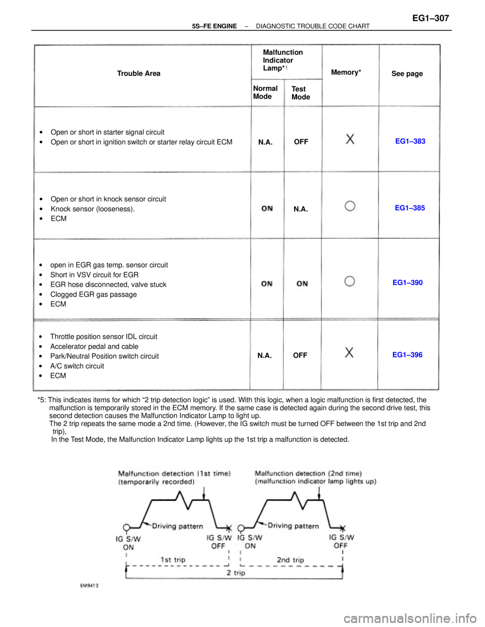
*5: This indicates items for which ª2 trip detection logicº is used. With this logic, when a logic malfunction is first detected, the
malfunction is temporarily stored in the ECM memory. If the same case is detected again during the second drive test, this
second detection causes the Malfunction Indicator Lamp to light up.
The 2 trip repeats the same mode a 2nd time. (However, the IG switch must be turned OFF between the 1st trip and 2nd
trip),
In the Test Mode, the Malfunction Indicator Lamp lights up the 1st trip a malfunction is detected.wopen in EGR gas temp. sensor circuit
wShort in VSV circuit for EGR
wEGR hose disconnected, valve stuck
wClogged EGR gas passage
wECM
wThrottle position sensor IDL circuit
wAccelerator pedal and cable
wPark/Neutral Position switch circuit
wA/C switch circuit
wECM wOpen or short in starter signal circuit
wOpen or short in ignition switch or starter relay circuit ECM
wOpen or short in knock sensor circuit
wKnock sensor (looseness).
wECMMalfunction
Indicator
Lamp*�
Normal
Mode Trouble AreaMemory*�
Test
ModeSee page
EG1±390EG1±385
EG1±396EG1±383
N.A.N.A.
N.A.
OFFOFF
± 5S±FE ENGINEDIAGNOSTIC TROUBLE CODE CHARTEG1±307
Page 369 of 4770
wManifold absolute pressure sensor
wThrottle position sensor Manifold absolute pressure sensor
wDefogger relay
wTaillight relay Engine coolant temp. sensorData link connector 1 and 2
Data link connector 1 and 2Malfunction indicator lamp Injectors (No.2 and No.4)
No.1 vehicle speed sensorThrottle position sensor
Throttle position sensorIntake air temp. sensorEG R gas temp. sensor
Circuit opening relay
Main oxygen sensor
Data link connector 1Sub oxygen sensor Terminal
No.Terminal
No.
A/C amplifier
EFI main relayEFI main relay Sensor ground
Sensor groundA/C amplifier
Power ground
ECM groundConnection Connection
VSV for EG R
Knock sensorSymbol Symbol
Battery Igniter
± 5S±FE ENGINETERMINALS OF ECMEG1±319
Page 371 of 4770
*�: Only for California specification vehicles.
*�: Except California specification vehicles with A/T.wStoplight switch
w Stoplight
w Park/neutral position switch wDefogger relay
wTaillight relay
Park/neutral position switchPark/neutral position switch
Park/neutral position switch
Malfunction indicator lampData link connector 1 and 2 Data link connector 1 and 2No.1 vehicle speed sensor
Throttle position sensor
Throttle position sensorEGR gas temp. sensor
Circuit opening relay Data link connector 1Data link connector 2
Cruise control ECUO/D main switch Terminal
No.Terminal
No.Connection
A/C amplifier
EFI main relay Sensor ground
Sensor ground
A/C amplifierEFI main relay
Knock sensorStarter relay Connection Symbol
Symbol
Battery
± 5S±FE ENGINETERMINALS OF ECMEG1±321
Page 435 of 4770

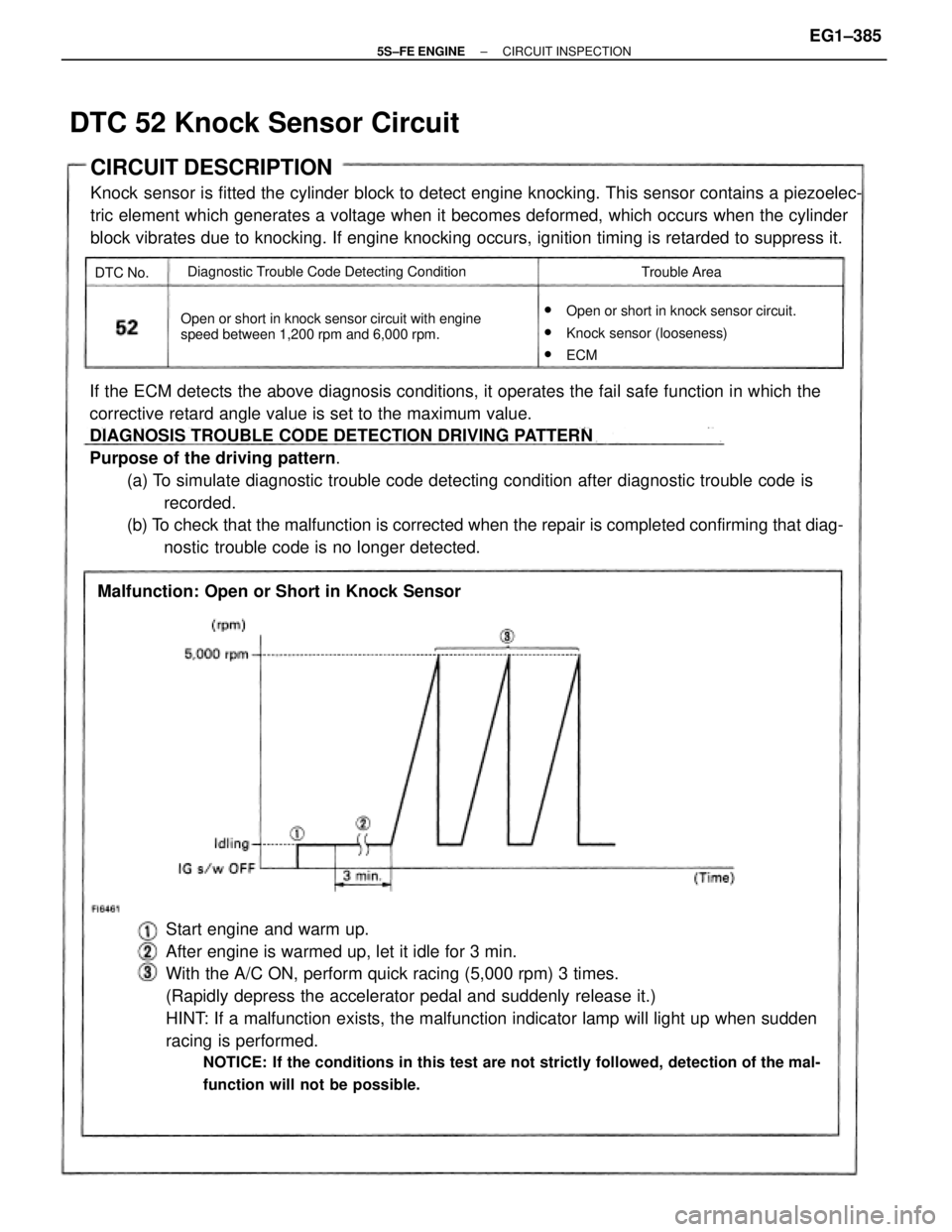
If the ECM detects the above diagnosis conditions, it operates the fail safe function in which the
corrective retard angle value is set to the maximum value.
DIAGNOSIS TROUBLE CODE DETECTION DRIVING PATTERN
Purpose of the driving pattern.
(a) To simulate diagnostic trouble code detecting condition after diagnostic trouble code is
recorded.
(b) To check that the malfunction is corrected when the repair is completed confirming that diag-
nostic trouble code is no longer detected.
Start engine and warm up.
After engine is warmed up, let it idle for 3 min.
With the A/C ON, perform quick racing (5,000 rpm) 3 times.
(Rapidly depress the accelerator pedal and suddenly release it.)
HINT: If a malfunction exists, the malfunction indicator lamp will light up when sudden
racing is performed.
NOTICE: If the conditions in this test are not strictly followed, detection of the mal-
function will not be possible.
CIRCUIT DESCRIPTION
Knock sensor is fitted the cylinder block to detect engine knocking. This sensor contains a piezoelec-
tric element which generates a voltage when it becomes deformed, which occurs when the cylinder
block vibrates due to knocking. If engine knocking occurs, ignition timing is retarded to suppress it.
w
Open or short in knock sensor circuit.
wKnock sensor (looseness)
wECM Open or short in knock sensor circuit with engine
speed between 1,200 rpm and 6,000 rpm.
Malfunction: Open or Short in Knock Sensor
Diagnostic Trouble Code Detecting Condition
Trouble Area
DTC 52 Knock Sensor Circuit
DTC No.
± 5S±FE ENGINECIRCUIT INSPECTIONEG1±385
Page 436 of 4770
Does malfunction disappear when a good knock
sensor is installed? Check for open and short in harness and
connector between knock sensor and ECM.Repair or replace harness or
connector. Check no continuity of knock sensor circuit.
DIAGNOSTIC CHART
WIRING DIAGRAM
Check and replace ECM.Replace knock sensor.Replace knock sensor. Check knock sensor.
YES
± 5S±FE ENGINECIRCUIT INSPECTIONEG1±386
Page 438 of 4770
Disconnect knock sensor connector.
Check for open and short in harness and connector between engine
control module and knock sensor (See page IN±31).
Does malfunction disappear when a good knock sensor is installed?
Check and replace engine control module.Replace knock sensor (See page EG1±93).
Replace knock sensor (See page EG1±93). Repair or replace harness or connector.
Check knock sensor.
YES
Measure resistance between the knock
sensor terminal and body.
Resistance: 1 M� or higher
± 5S±FE ENGINECIRCUIT INSPECTIONEG1±388