Page 4388 of 4770
SA082±01
W03208
W03209
SA±48
± SUSPENSION AND AXLEFRONT STABILIZER BAR
1999 Author�: Date�:
REMOVAL
1. REMOVE LEFT AND RIGHT FRONT WHEELS
Torque: 103 N´m (1,050 kgf´cm, 76 ft´lbf)
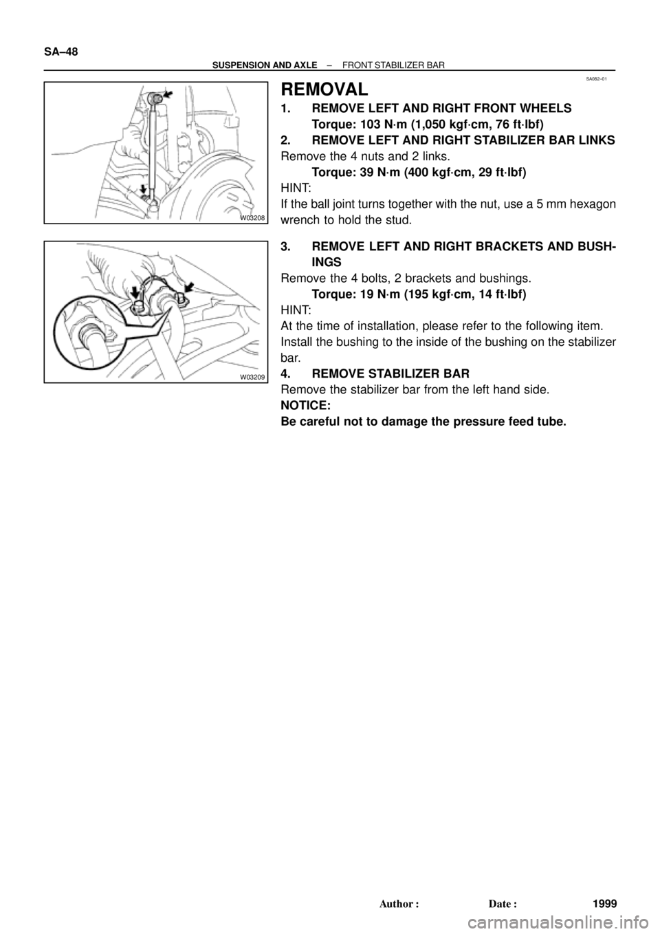
2. REMOVE LEFT AND RIGHT STABILIZER BAR LINKS
Remove the 4 nuts and 2 links.
Torque: 39 N´m (400 kgf´cm, 29 ft´lbf)
HINT:
If the ball joint turns together with the nut, use a 5 mm hexagon
wrench to hold the stud.
3. REMOVE LEFT AND RIGHT BRACKETS AND BUSH-
INGS
Remove the 4 bolts, 2 brackets and bushings.
Torque: 19 N´m (195 kgf´cm, 14 ft´lbf)
HINT:
At the time of installation, please refer to the following item.
Install the bushing to the inside of the bushing on the stabilizer
bar.
4. REMOVE STABILIZER BAR
Remove the stabilizer bar from the left hand side.
NOTICE:
Be careful not to damage the pressure feed tube.
Page 4392 of 4770

2. w/ DISC BRAKE:
REMOVE BRAKE CALIPE")
SA086±01
R10948
Z00206
SA±52
± SUSPENSION AND AXLEREAR AXLE HUB
2003 Author�: Date�:
REMOVAL
1. REMOVE REAR WHEEL
Torque: 103 N´m (1,050 kgf´cm, 76 ft´lbf)
2. w/ DISC BRAKE:
REMOVE BRAKE CALIPER AND DISC
(a) Remove the brake caliper and disc.
Torque: 47 N´m (475 kgf´cm, 34 ft´lbf)
(b) Support the brake caliper securely.
3. w/ DRUM BRAKE:
REMOVE BRAKE DRUM
4. CHECK BEARING BACKLASH AND AXLE HUB DEVI-
ATION
(a) Using a dial indicator near the center of the axle hub and
check the backlash in the bearing shaft direction.
Maximum: 0.05 mm (0.0020 in.)
If the backlash exceeds the maximum, replace the axle hub with
the bearing.
(b) Using a dial indicator, check the deviation at the surface
of the axle hub outside the hub bolt.
Maximum: 0.07 mm (0.0028 in.)
If the deviation exceeds the maximum, replace the axle hub
with the bearing.
5. REMOVE REAR AXLE HUB
(a) Remove the 4 bolts and rear axle hub.
Torque: 80 N´m (820 kgf´cm, 59 ft´lbf)
(b) Remove the O±ring.
HINT:
At the time of installation, coat a new O±ring with MP grease.
Page 4397 of 4770

2. REMOVE REAR WHEEL
Torque: 103")
SA08A±01
R00749
R10288
W03213
± SUSPENSION AND AXLEREAR SHOCK ABSORBER
SA±57
2008 Author�: Date�:
REMOVAL
1. REMOVE REAR SIDE SEATBACK
(See page BO±113 or BO±118)
2. REMOVE REAR WHEEL
Torque: 103 N´m (1,050 kgf´cm, 76 ft´lbf)
3. REMOVE FLEXIBLE HOSE AND ABS SPEED SEN-
SOR WIRE HARNESS (w/ ABS) FROM SHOCK AB-
SORBER
Remove the 2 bolts, flexible hose bracket and ABS wire har-
ness clamp.
Torque:
Flexible hose: 29 N´m (300 kgf´cm, 22 ft´lbf)
ABS wire: 5.5 N´m (56 kgf´cm, 49 in.´lbf)
4. DISCONNECT STABILIZER BAR LINK FROM SHOCK
ABSORBER (See page SA±70)
5. REMOVE SHOCK ABSORBER WITH COIL SPRING
(a) Loosen the 2 nuts on the lower side of the shock absorber.
Torque:
Reused nut: 196 N´m (2,000 kgf´cm, 145 ft´lbf)
New nut: 255 N´m (2,600 kgf´cm, 188 ft´lbf)
HINT:
At the time of installation, coat the nut's threads with engine oil.
(b) Support the rear axle carrier with a jack.
(c) Remove the cap.
(d) Loosen the nut in the middle of the suspension support.
NOTICE:
Do not remove it.
Torque: 49 N´m (500 kgf´cm, 36 ft´lbf)
(e) Remove the 3 nuts of the suspension support.
Torque: 39 N´m (400 kgf´cm, 29 ft´lbf)
(f) Lower the rear axle carrier and remove the 2 bolts.
(g) Remove the shock absorber with the coil spring.
Page 4404 of 4770

SA08H±01
W03216
W03217
Rear
W03219A B
A B SA±64
± SUSPENSION AND AXLEREAR LOWER SUSPENSION ARM AND STRUT ROD
2015 Author�: Date�:
REMOVAL
1. REMOVE REAR WHEEL
Torque: 103 N´m (1,050 kgf´cm, 76 ft´lbf)
2. REMOVE EXHAUST CENTER PIPE
5S±FE Engine: (See page EM±114)
1MZ±FE Engine: (See page EM±111)
3. REMOVE STRUT ROD
(a) Remove the bolt and disconnect the parking brake cable.
Torque: 5.4 N´m (55 kgf´cm, 48 in.´lbf)
(b) Remove the 2 bolts and nuts.
Torque: 113 N´m (1,150 kgf´cm, 83 ft´lbf)
HINT:
At the time of installtion,after stabilizing the suspension, torque
the bolts.
(c) Remove the strut rod.
4. REMOVE NO.2 LOWER SUSPENSION ARM
(a) Remove the 3 nuts, suspension arm washer and wash-
ers.
Torque: 181 N´m (1,850 kgf´cm, 134 ft´lbf)
HINT:
At the time of installtion, after stabilizing the suspension, torque
the nuts.
(b) Remove the No.2 lower suspension arm.
HINT:
At the time of installtion, face the paint mark to the rearward.
5. REMOVE LEFT AND RIGHT STABILIZER BRACKETS
(See page SA±70)
6. REMOVE NO.1 LOWER SUSPENSION ARM
(a) Support the suspension member with a jack.
(b) Remove the 4 nuts, 2 bolts and suspension member low-
er stoppers.
Torque:
Bolt: 51 N´m (520 kgf´cm, 38 ft´lbf)
Nut A: 51 N´m (520 kgf´cm, 38 ft´lbf)
Nut B: 38 N´m (390 kgf´cm, 28 ft´lbf)
(c) Lower the suspension member.
Page 4410 of 4770
SA08M±01
W03225
W03226
SA±70
± SUSPENSION AND AXLEREAR STABILIZER BAR
2021 Author�: Date�:
REMOVAL
1. REMOVE REAR WHEELS
Torque: 103 N´m (1,050 kgf´cm, 76 ft´lbf)
2. REMOVE LEFT AND RIGHT STABILIZER BAR LINKS
Remove the 4 nuts and 2 links.
HINT:
If the ball joint turns together with the nut, use a 5 mm hexagon
wrench to hold the stud.
Torque: 39 N´m (400 kgf´cm, 29 ft´lbf)
3. REMOVE HEAT INSULATOR
Remove the 3 bolts, clip and heat insulator.
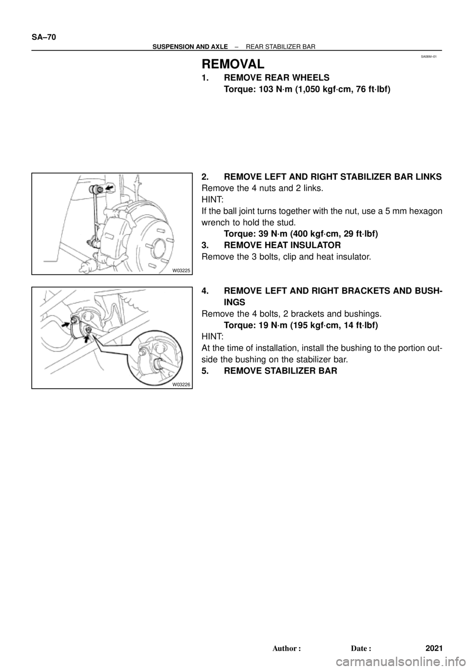
4. REMOVE LEFT AND RIGHT BRACKETS AND BUSH-
INGS
Remove the 4 bolts, 2 brackets and bushings.
Torque: 19 N´m (195 kgf´cm, 14 ft´lbf)
HINT:
At the time of installation, install the bushing to the portion out-
side the bushing on the stabilizer bar.
5. REMOVE STABILIZER BAR