Page 4306 of 4770
 Torque the 4 column assembly set nuts.
Torque:")
SR06M±01
W03303
Matchmarks
W02655
Mark SR±16
± STEERINGTILT STEERING COLUMN
2111 Author�: Date�:
INSTALLATION
1. INSTALL STEERING COLUMN ASSEMBLY
(a) Torque the 4 column assembly set nuts.
Torque: 25 N´m (260 kgf´cm, 19 ft´lbf)
(b) Connect the connectors.
2. INSTALL INTERMEDIATE SHAFT ASSEMBLY
Torque the bolt.
Torque: 35 N´m (360 kgf´cm, 26 ft´lbf)
3. CONNECT INTERMEDIATE SHAFT ASSEMBLY
(a) Align the matchmarks on the intermediate shaft and con-
trol valve shaft.
(b) Torque the bolt.
Torque: 35 N´m (360 kgf´cm, 26 ft´lbf)
4. INSTALL SPIRAL CABLE
(See page BE±23)
5. INSTALL COMBINATION SWITCH WITH SPIRAL
CABLE
(a) Tighten the 3 screws.
(b) Connect the airbag connector.
(c) Connect the 3 connectors.
6. INSTALL LOWER INSTRUMENT FINISH PANEL
7. INSTALL LH LOWER INSTRUMENT PANEL
Tighten the 4 bolts.
8. INSTALL No.1 LOWER INSTRUMENT PANEL
(a) Connect the hood lock control cable.
(b) Tighten the 2 screws.
9. INSTALL COWL SIDE TRIM
Install the clip.
10. INSTALL FRONT DOOR INSIDE SCUFF PLATE
11. INSTALL UPPER AND LOWER COLUMN COVERS
(a) Tighten the 3 screws.
(b) Install the lower No.2 cover to the lower cover.
12. CENTER SPIRAL CABLE
(a) Check that the front wheels are facing straight ahead.
(b) Turn the cable counterclockwise by hand until it becomes
harder to turn the cable.
(c) Then rotate the cable clockwise about 3 turns to align the
mark.
HINT:
The cable will rotate about 3 turns to either left or right of the
center.
Page 4324 of 4770
SR06U±01
W04222
SST SR±34
± STEERINGPOWER STEERING GEAR
2129 Author�: Date�:
REMOVAL
1. PLACE FRONT WHEELS FACING STRAIGHT AHEAD
2. REMOVE STEERING WHEEL PAD
(See page SR±11)
3. REMOVE STEERING WHEEL
(See page SR±11)
4. DISCONNECT RH AND LH TIE ROD ENDS
(See page SA±10)
5. DISCONNECT INTERMEDIATE SHAFT ASSEMBLY
(See page SR±11)
6. DISCONNECT CLAMP PLATE
Remove the nut.
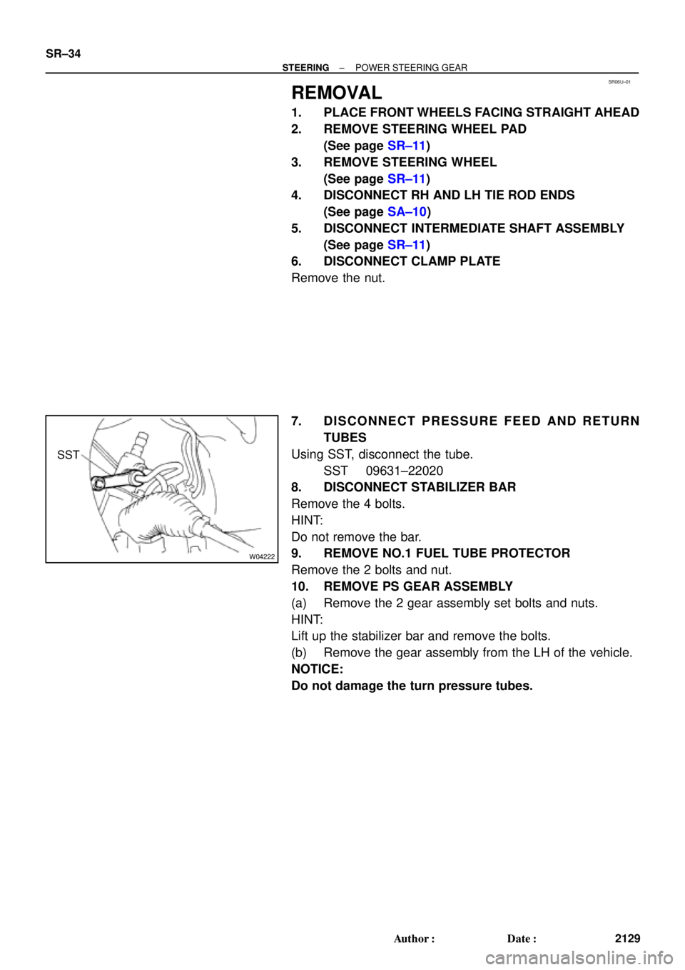
7. DISCONNECT PRESSURE FEED AND RETURN
TUBES
Using SST, disconnect the tube.
SST 09631±22020
8. DISCONNECT STABILIZER BAR
Remove the 4 bolts.
HINT:
Do not remove the bar.
9. REMOVE NO.1 FUEL TUBE PROTECTOR
Remove the 2 bolts and nut.
10. REMOVE PS GEAR ASSEMBLY
(a) Remove the 2 gear assembly set bolts and nuts.
HINT:
Lift up the stabilizer bar and remove the bolts.
(b) Remove the gear assembly from the LH of the vehicle.
NOTICE:
Do not damage the turn pressure tubes.
Page 4339 of 4770
 Install the gear assembly from the LH of the vehicle.
NOTICE")
SR06Y±01
W04224
SST
Fulcrum
Length
± STEERINGPOWER STEERING GEAR
SR±49
2144 Author�: Date�:
INSTALLATION
1. INSTALL PS GEAR ASSEMBLY
(a) Install the gear assembly from the LH of the vehicle.
NOTICE:
Do not damage the turn pressure tubes.
(b) Torque the 2 gear assembly set bolts and nuts.
Torque: 181 N´m (1,850 kgf´cm, 134 ft´lbf)
HINT:
Lift up the stabilizer bar and install the bolts.
2. INSTALL NO.1 FUEL TUBE PROTECTOR
Install the 2 bolts and nut.
3. CONNECT STABILIZER BAR
Torque the 4 bolts.
Torque: 19 N´m (195 kgf´cm, 14 ft´lbf)
4. CONNECT PRESSURE FEED AND RETURN TUBES
Using SST, connect the tube.
SST 09631±22020
Torque: 32 N´m (326 kgf´cm, 24 ft´lbf)
HINT:
�Use a torque wrench with a fulcrum length of 300 mm
(11.81 in.).
�This torque value is effective in case that SST is parallel
to a torque wrench.
5. CONNECT CLAMP PLATE
Torque the nut.
Torque: 10 N´m (100 kgf´cm, 7 ft´lbf)
6. CONNECT INTERMEDIATE SHAFT ASSEMBLY
(See page SR±16)
7. CONNECT RH AND LH TIE ROD ENDS
(See page SA±10)
8. POSITION FRONT WHEELS FACING STRAIGHT
AHEAD
HINT:
Do it with the front of the vehicle jacked up.
9. CENTER SPIRAL CABLE
(See page SR±16)
10. INSTALL STEERING WHEEL
(a) Install the wheel at straight±ahead position.
(b) Temporarily tighten the wheel set nut.
(c) Connect the connector.
11. BLEED POWER STEERING SYSTEM
(See page SR±4)
12. CHECK STEERING WHEEL CENTER POINT
Page 4345 of 4770

W03086
F02267
1
2
F01195
Bolt
Adjusting
ValueSet Bolt
15'
30'Adjusting Bolt90105±15001 90105±15004 90105±15005 90105±15006
45'
1°00'
1°15'
1°30'121212121 Dot 2 Dots 3 Dots
± SUSPENSION AND AXLEFRONT WHEEL ALIGNMENT
SA±5
1956 Author�: Date�:
5. ADJUST CAMBER
NOTICE:
After the camber has been adjusted, inspect the toe±in.
(a) Remove the front wheels and speed sensor clamp.
(b) Remove the 2 nuts on the lower side of the shock absorb-
er.
(c) Coat the threads of the nuts with engine oil.
(d) Temporarily install the 2 nuts.
(e) Adjust the camber by pushing or pulling the lower side of
the shock absorber in the direction in which the camber
adjustment is required.
(f) Tighten the nuts.
Torque: 211 N´m (2,150 kgf´cm, 156 ft´lbf)
(g) Install the front wheels.
Torque: 103 N´m (1,050 kgf´cm, 76 ft´lbf)
(h) Check the camber.
HINT:
�Try to adjust the camber to the center value.
�Adjusting value for the set bolts is 6' ± 30' (0.1° ± 0.5°).
If the camber is not within the specification, using the table be-
low, estimate for how much additional camber adjustment will
be required, and select the camber adjusting bolt.
(i) Follow the above mentioned steps again. Between step
(b) and (c), exchange 1 or 2 selected bolts.
HINT:
When exchanging the 2 bolts, exchange 1 bolt for each time.
Page 4350 of 4770

2. CHECK BE")
SA07C±01
W03084W03084
W03093
W03139
W03094
SST
SA±10
± SUSPENSION AND AXLEFRONT AXLE HUB
1961 Author�: Date�:
REMOVAL
1. REMOVE FRONT WHEEL
Torque: 103 N´m (1,050 kgf´cm, 76 ft´lbf)
2. CHECK BEARING BACKLASH AND AXLE HUB DEVI-
ATION
(a) Remove the 2 bolts, brake caliper and disc.
(b) Support the brake caliper securely.
(c) Using a dial indicator near the center of the axle hub and
check the backlash in the bearing shaft direction.
Maximum: 0.05 mm (0.0020 in.)
If the backlash exceeds the maximum, replace the bearing.
(d) Using a dial indicator, check the deviation at the surface
of the axle hub outside the hub bolt.
Maximum: 0.05 mm (0.0020 in.)
If the deviation exceeds the maximum, replace the bearing.
(e) Install the disc, 2 bolts and brake caliper.
Torque: 107 N´m (1,090 kgf´cm, 79 ft´lbf)
3. REMOVE DRIVE SHAFT LOCK NUT
(a) Remove the cotter pin and lock cap.
(b) With applying the brakes, remove the nut.
Torque: 294 N´m (3,000 kgf´cm, 217 ft´lbf)
(c) Remove the brake caliper and disc.
4. w/ ABS:
REMOVE ABS SPEED SENSOR AND WIRE HARNESS
CLAMP
Torque: 8.0 N´m (82 kgf´cm, 71 in.´lbf)
5. LOOSEN 2 NUTS ON LOWER SIDE OF SHOCK AB-
SORBER
Torque: 211 N´m (2,150 kgf´cm, 156 ft´lbf)
HINT:
�Do not remove the bolts.
�At the time of installation, coat the nut's thread with en-
gine oil.
6. DISCONNECT TIE ROD END FROM STEERING
KNUCKLE
(a) Remove the cotter pin and nut.
Torque: 49 N´m (500 kgf´cm, 36 ft´lbf)
(b) Using SST, disconnect the tie rod end from the steering
knuckle.
SST 09610±20012
Page 4355 of 4770
W03096
SST
SA07G±01
W03097
± SUSPENSION AND AXLEFRONT WHEEL HUB BOLT
SA±15
1966 Author�: Date�:
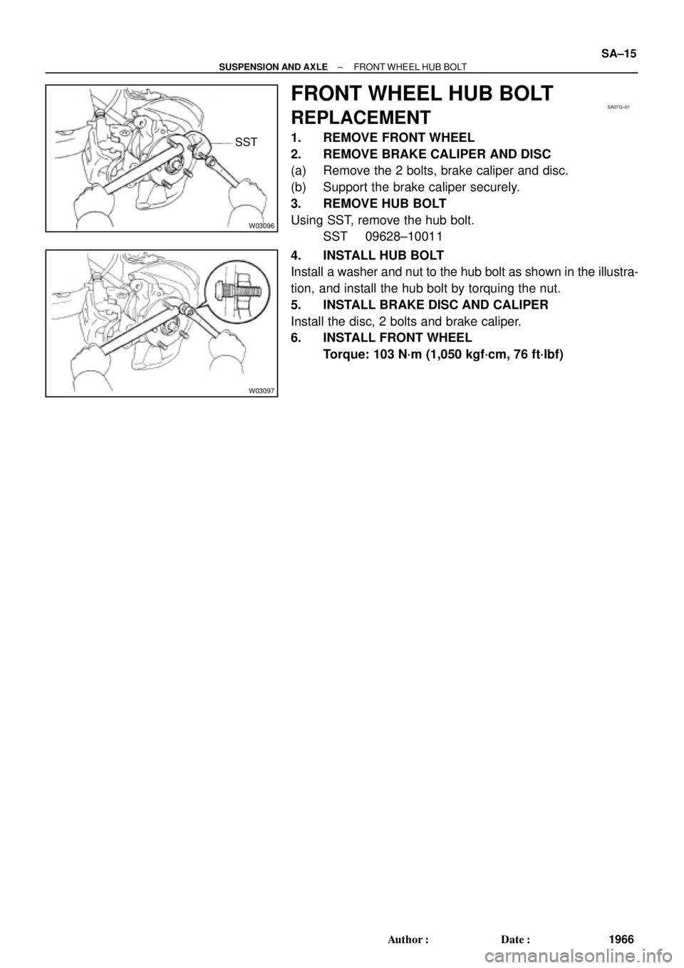
FRONT WHEEL HUB BOLT
REPLACEMENT
1. REMOVE FRONT WHEEL
2. REMOVE BRAKE CALIPER AND DISC
(a) Remove the 2 bolts, brake caliper and disc.
(b) Support the brake caliper securely.
3. REMOVE HUB BOLT
Using SST, remove the hub bolt.
SST 09628±10011
4. INSTALL HUB BOLT
Install a washer and nut to the hub bolt as shown in the illustra-
tion, and install the hub bolt by torquing the nut.
5. INSTALL BRAKE DISC AND CALIPER
Install the disc, 2 bolts and brake caliper.
6. INSTALL FRONT WHEEL
Torque: 103 N´m (1,050 kgf´cm, 76 ft´lbf)
Page 4374 of 4770

2. REMOVE FLEXIBLE HOSE AN")
SA07N±01
Z19346
To Outside SA±34
± SUSPENSION AND AXLEFRONT SHOCK ABSORBER
1985 Author�: Date�:
REMOVAL
1. REMOVE FRONT WHEEL
Torque: 103 N´m (1,050 kgf´cm, 76 ft´lbf)
2. REMOVE FLEXIBLE HOSE AND ABS SPEED SEN-
SOR WIRE HARNESS (w/ ABS) AND CLAMP FROM
SHOCK ABSORBER
Remove the bolt, flexible hose and ABS wire harness clamp.
Torque: 29 N´m (300 kgf´cm, 22 ft´lbf)
3. DISCONNECT STABILIZER BAR LINK FROM SHOCK
ABSORBER (See page SA±48)
4. DISCONNECT SHOCK ABSORBER FROM STEERING
KNUCKLE
(a) Remove the 2 nuts and bolts on the lower side of the
shock absorber.
Torque: 211 N´m (2,150 kgf´cm, 156 ft´lbf)
(b) Remove the shock absorber from the steering knuckle.
HINT:
At the time of installation, coat the nut's threads with engine oil.
5. REMOVE SHOCK ABSORBER WITH COIL SPRING
Remove the 3 nuts, suspension support No.2 and shock ab-
sorber with the coil spring.
Torque: 80 N´m (820 kgf´cm, 59 ft´lbf)
HINT:
At the time of installation rotate the suspension support and set
it in the direction, as shown in the illustration.
Page 4381 of 4770
SA07U±01
W03202
W03203
W03204
± SUSPENSION AND AXLEFRONT LOWER SUSPENSION ARM
SA±41
1992 Author�: Date�:
REMOVAL
1. REMOVE FRONT WHEEL
Torque: 103 N´m (1,050 kgf´cm, 76 ft´lbf)
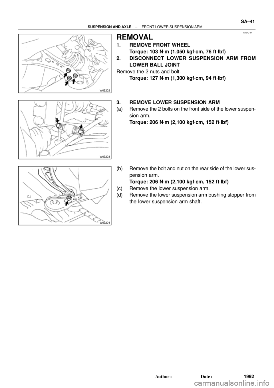
2. DISCONNECT LOWER SUSPENSION ARM FROM
LOWER BALL JOINT
Remove the 2 nuts and bolt.
Torque: 127 N´m (1,300 kgf´cm, 94 ft´lbf)
3. REMOVE LOWER SUSPENSION ARM
(a) Remove the 2 bolts on the front side of the lower suspen-
sion arm.
Torque: 206 N´m (2,100 kgf´cm, 152 ft´lbf)
(b) Remove the bolt and nut on the rear side of the lower sus-
pension arm.
Torque: 206 N´m (2,100 kgf´cm, 152 ft´lbf)
(c) Remove the lower suspension arm.
(d) Remove the lower suspension arm bushing stopper from
the lower suspension arm shaft.