Page 3855 of 4770
PP±4
± PREPARATIONENGINE MECHANICAL (5S±FE)
56 Author�: Date�:
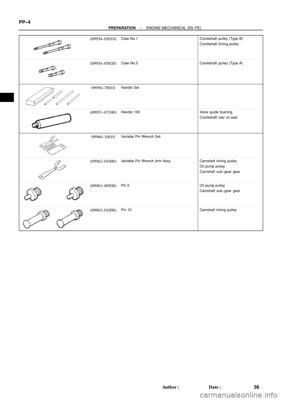
(09954±05010)Claw No.1Crankshaft pulley (Type B)
Crankshaft timing pulley
(09954±05020)Claw No.2Crankshaft pulley (Type A)
09950±70010Handle Set
(09951±07100)Handle 100Valve guide bushing
Crankshaft rear oil seal
09960±10010Variable Pin Wrench Set
(09962±01000)Variable Pin Wrench Arm AssyCamshaft timing pulley
Oil pump pulley
Camshaft sub±gear gear
(09963±00500)Pin 5Oil pump pulley
Camshaft sub±gear gear
(09963±01000)Pin 10Camshaft timing pulley
Page 4038 of 4770
SFI SYSTEM
1437 Author�:")
Z11336
California
Except CaliforniaGrommetInsulator O±Ring
InjectorO±Ring
O±Ring
Grommet
InjectorInsulator
S04583
Pull
S05040
Vinyl Bag
S05382
Retainer
SF±4
± SFI (5S±FE)SFI SYSTEM
1437 Author�: Date�:
(e) Install the injector to the delivery pipe and cylinder head,
as shown in the illustration.
Before installing the injector, must apply spindle oil or gas-
oline on the place where a delivery pipe or an intake man-
ifold touches an O±ring of the injector.
(f) Observe these precautions when disconnecting the fuel
tube connector (quick type):
(1) Check if there is any dirt like mud on the pipe and
around the connector before disconnecting them
and clean the dirt away.
(2) Be sure to disconnect with hands.
(3) When the connector and the pipe are stuck, pinch
the retainer between the hands, push and pull the
connector to free to disconnect and pull it out. Do
not use any tool at this time.
(4) Inspect if there is any dirt or the likes on the seal sur-
face of the disconnected pipe and clean it away.
(5) Prevent the disconnected pipe and connector from
damaging and mixing foreign objects by covering
them with a vinyl bag.
(g) Observe these precautions when connecting the fuel
tube connector (quick type):
(1) Do not reuse the retainer removed from the pipe.
(2) Must use hands without using tools when to remove
the retainer from the pipe.
(3) Check if there is any damage or foreign objects on
the connected part of the pipe.
Page 4104 of 4770
SFI")
B00630
O±Ring
Grommet
Spacer InsulatorDelivery Pipe California A/T
Except California A/TO±Ring
O±Ring
Grommet
Spacer InsulatorDelivery Pipe
O±Ring
S04583
S05040
Vinyl Bag SF±4
± SFI (1MZ±FE)SFI SYSTEM
1503 Author�: Date�:
(e) Install the injector to the delivery pipe and intake manifold,
as shown in the illustration.
Before installing the injector, must apply spindle oil or gas-
oline on the place where a delivery pipe or an intake man-
ifold touches an O±ring of the injector.
(f) Observe these precautions when disconnecting the fuel
tube connector (quick type).
(1) Check if there is any dirt like mud on the pipe and
around the connector before disconnecting them
and clean the dirt away.
(2) Be sure to disconnect with hands.
(3) When the connector and the pipe are stuck, pinch
the retainer between the hands, push and pull the
connector to free to disconnect and pull it out. Do
not use any tool at this time.
(4) Inspect if there is any dirt or the likes on the seal sur-
face of the disconnected pipe and clean it away.
(5) Prevent the disconnected pipe and connector from
damaging and mixing foreign objects by covering
them with a vinyl bag.
Page 4105 of 4770
SFI SYSTEM
SF±5
1504 Author�: Date�:
(g) Observe these precautions when connecting the fuel
tube connector (quick ty")
S05382
Retainer
S05050
Click Sound
S05358
TOYOTA
Hand±Held Tester
± SFI (1MZ±FE)SFI SYSTEM
SF±5
1504 Author�: Date�:
(g) Observe these precautions when connecting the fuel
tube connector (quick type).
(1) Do not reuse the retainer removed from the pipe.
(2) Must use hands without using tools when to remove
the retainer from the pipe.
(3) Check if there is any damage or foreign objects on
the connected part of the pipe.
(4) Match the axis of the connector with axis of the pipe,
and push in the connector until the retainer makes
a ºclickº sound. In case that the connections is tight,
apply little amount of new engine oil on the tip of the
pipe.
(5) After having finished the connection, check if the
pipe and the connector are securely connected by
pulling them.
(6) Check if there is any fuel leakage.
(h) Observe these precautions when handling nylon tube.
(1) Pay attention not to turn the connected part of the
nylon tube and the quick connector with force when
connecting them.
(2) Pay attention not to kink the nylon tube.
(3) Do not remove the EPDM protector on the outside
of the nylon tube.
(4) Must not close the piping with the nylon tube by
bending it.
(i) Check that there are no fuel leaks after doing mainte-
nance anywhere on the fuel system.
(1) Connect a TOYOTA hand±held tester to the DLC3.
(2) Turn the ignition switch ON and push the TOYOTA
hand±held tester main switch ON.
NOTICE:
Do not start the engine.
(3) Select the active test mode on the TOYOTA hand±
held tester.
(4) Please refer to the TOYOTA hand±held tester oper-
ator 's manual for further details.
(5) If you have no TOYOTA hand±held tester, connect
the positive (+) and negative (±) leads from the bat-
tery to the fuel pump connector.
(See page SF±6)
(6) Check that there are no leaks from any part of the
fuel system.
(7) Turn the ignition switch to LOCK.
(8) Disconnect the TOYOTA hand±held tester from the
DLC3.
Page 4108 of 4770
FUEL PUMP
1507 Author�: Date�:
(p) After checking fuel pressure, disconnect the negative (±)
terminal cable")
S05351
S06086
Fuel Hose
Clamp
S04508
Ohmmeter
4 5
S04509
4 5
Battery SF±8
± SFI (1MZ±FE)FUEL PUMP
1507 Author�: Date�:
(p) After checking fuel pressure, disconnect the negative (±)
terminal cable from the battery and carefully remove the
SST and fuel tube connector to prevent gasoline from
splashing.
SST 09268±41047, 09268±41250, 09268±45012
(q) Reconnect the No.1 fuel pipe (fuel tube connector).
CAUTION:
Perform connecting operations of the fuel tube connector
(quick type) after observing the precautions.
(See page SF±1)
(r) Surely install the fuel hose clamp to the fuel filter with
ºclickº sound.
(s) After installing the clamp, check that the clamp is fixed by
pulling up the clamp.
(t) Reconnect the negative (±) terminal cable to the battery.
(u) Check for fuel leaks.
3. REMOVE REAR SEAT CUSHION
4. REMOVE FLOOR SERVICE HOLE COVER
5. DISCONNECT FUEL PUMP & SENDER GAUGE
CONNECTOR
6. INSPECT FUEL PUMP RESISTANCE
Using an ohmmeter, measure the resistance between terminals
4 and 5.
Resistance: 0.2 ± 3.0 W at 20°C (68°F)
If the resistance is not as specified, replace the fuel pump.
7. INSPECT FUEL PUMP OPERATION
Connect the positive (+) lead from the battery to terminal 4 of
the connector, and the negative (±) lead to terminal 5. Check
that the fuel pump operates.
NOTICE:
�These tests must be done quickly (within 10 seconds)
to prevent the coil burning out.
�Keep the fuel pump as far away from the battery as
possible.
�Always do the switching at the battery side.
Page 4129 of 4770
INJECTOR
SF±29
1528 Author�: Date�:
(g) Apply a light coat of spindle oil or gasoline on the place
where a intake manifold touc")
B01021
S04728
Rotate
Outward
B01020
S06525
Align
S05351
± SFI (1MZ±FE)INJECTOR
SF±29
1528 Author�: Date�:
(g) Apply a light coat of spindle oil or gasoline on the place
where a intake manifold touches an O±ring of the injector.
(h) Place the delivery pipes and fuel pipe together with the 6
injectors in position on the intake manifold.
(i) Temporarily install the 4 bolts holding the delivery pipes
to the intake manifold.
(j) Temporarily install the bolt holding the No.1 fuel pipe to
the intake manifold.
(k) Check that the injectors rotate smoothly.
HINT:
If injectors do not rotate smoothly, the probable cause is incor-
rect installation of O±rings. Replace the O±rings.
(l) Position the injector connector outward.
(m) Tighten the 4 bolts holding the delivery pipes to the intake
manifold.
Torque: 10 N´m (100 kgf´cm, 7 ft´lbf)
(n) Tighten the bolt holding the No.1 fuel pipe to the intake
manifold.
Torque: 19.5 N´m (200 kgf´cm, 14 ft´lbf)
2. CONNECT NO.1 FUEL PIPE
(a) Align the alignment marks (white paint) on the No.1 fuel
pipe.
(b) Connect the No.1 fuel pipe (fuel tube connector) to the
fuel filter.
CAUTION:
Perform connecting operations of the fuel tube connector
(quick type) after observing the precaution.
(See page SF±1)
Page 4375 of 4770
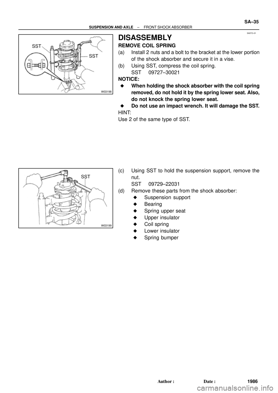
SA07O±01
W03198
SST
SST
W03199
SST
± SUSPENSION AND AXLEFRONT SHOCK ABSORBER
SA±35
1986 Author�: Date�:
DISASSEMBLY
REMOVE COIL SPRING
(a) Install 2 nuts and a bolt to the bracket at the lower portion
of the shock absorber and secure it in a vise.
(b) Using SST, compress the coil spring.
SST 09727±30021
NOTICE:
�When holding the shock absorber with the coil spring
removed, do not hold it by the spring lower seat. Also,
do not knock the spring lower seat.
�Do not use an impact wrench. It will damage the SST.
HINT:
Use 2 of the same type of SST.
(c) Using SST to hold the suspension support, remove the
nut.
SST 09729±22031
(d) Remove these parts from the shock absorber:
�Suspension support
�Bearing
�Spring upper seat
�Upper insulator
�Coil spring
�Lower insulator
�Spring bumper
Page 4378 of 4770

SA07R±01
W03200
SST
W03201
W03199
SST SA±38
± SUSPENSION AND AXLEFRONT SHOCK ABSORBER
1989 Author�: Date�:
REASSEMBLY
1. INSTALL LOWER INSULATOR ONTO SHOCK AB-
SORBER
2. INSTALL SPRING BUMPER TO PISTON ROD
3. INSTALL COIL SPRING
(a) Using SST, compress the coil spring.
SST 09727±30021
NOTICE:
Do not use an impact wrench. It will damage the SST.
HINT:
Use 2 of the same type of SST.
(b) Install the coil spring to the shock absorber.
HINT:
Fit the lower end of the coil spring into the gap of the spring low-
er seat.
4. INSTALL SPRING UPPER SEAT AND INSULATOR
(a) Align the 'OUT' mark of spring upper seat with the mark
of the upper insulator.
(b) Install the spring upper seat with upper insulator to the
shock absorber with the mark facing the outside of the ve-
hicle.
(c) Install the bearing and suspension support.
(d) Using SST to hold the suspension support, install a new
nut.
SST 09729±22031
Torque: 49 N´m (500 kgf´cm, 36 ft´lbf)
(e) Remove the SST from the coil spring.
SST 09727±30021
NOTICE:
Check that the bearing fits into the recess in the suspen-
sion support.