Page 151 of 4770

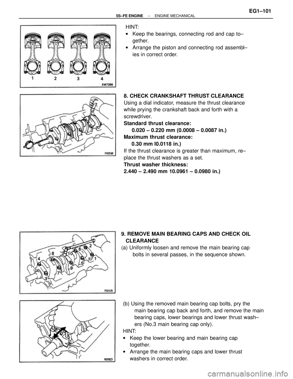
8. CHECK CRANKSHAFT THRUST CLEARANCE
Using a dial indicator, measure the thrust clearance
while prying the crankshaft back and forth with a
screwdriver.
Standard thrust clearance:
0.020 ± 0.220 mm (0.0008 ± 0.0087 in.)
Maximum thrust clearance:
0.30 mm l0.0118 in.)
If the thrust clearance is greater than maximum, re±
place the thrust washers as a set.
Thrust washer thickness:
2.440 ± 2.490 mm 10.0961 ± 0.0980 in.)
(b) Using the removed main bearing cap bolts, pry the
main bearing cap back and forth, and remove the main
bearing caps, lower bearings and lower thrust wash±
ers (No.3 main bearing cap only).
HINT:
wKeep the lower bearing and main bearing cap
together.
wArrange the main bearing caps and lower thrust
washers in correct order. HINT:
wKeep the bearings, connecting rod and cap to±
gether.
wArrange the piston and connecting rod assembl±
ies in correct order.
9. REMOVE MAIN BEARING CAPS AND CHECK OIL
CLEARANCE
(a) Uniformly loosen and remove the main bearing cap
bolts in several passes, in the sequence shown.
± 5S±FE ENGINEENGINE MECHANICALEG1±101
Page 153 of 4770

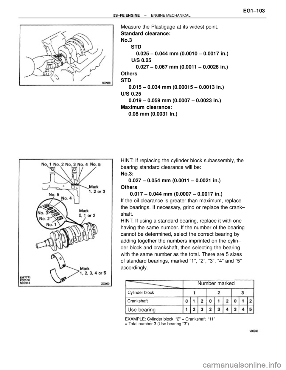
HINT: If replacing the cylinder block subassembly, the
bearing standard clearance will be:
No.3:
0.027 ± 0.054 mm (0.0011 ± 0.0021 in.)
Others
0.017 ± 0.044 mm (0.0007 ± 0.0017 in.)
If the oil clearance is greater than maximum, replace
the bearings. If necessary, grind or replace the crank±
shaft.
HINT: If using a standard bearing, replace it with one
having the same number. If the number of the bearing
cannot be determined, select the correct bearing by
adding together the numbers imprinted on the cylin±
der block and crankshaft, then selecting the bearing
with the same number as the total. There are 5 sizes
of standard bearings, marked ª1º, ª2º, ª3º, ª4º and ª5º
accordingly.Measure the Plastigage at its widest point.
Standard clearance:
No.3
STD
0.025 ± 0.044 mm (0.0010 ± 0.0017 in.)
U/S 0.25
0.027 ± 0.067 mm (0.0011 ± 0.0026 in.)
Others
STD
0.015 ± 0.034 mm (0.00015 ± 0.0013 in.)
U/S 0.25
0.019 ± 0.059 mm (0.0007 ± 0.0023 in.)
Maximum clearance:
0.08 mm (0.0031 In.)
EXAMPLE: Cylinder block ª2º + Crankshaft ª11º
= Total number 3 (Use bearing ª3º)Cylinder block
Number marked
Use bearing
Crankshaft
± 5S±FE ENGINEENGINE MECHANICALEG1±103
Page 157 of 4770
PISTON AND CONNECTING ROD ASSY
DISASSEMBLY
1. CHECK FIT BETWEEN PISTON AND PISTON PIN
Try to move the piston back and forth on the piston
pin.
If any movement is felt, replace the piston and pin as
a set.
2. REMOVE PISTON RINGS
(a) Using a piston ring expander, remove the 2 compres±
sion rings.
3. DISCONNECT CONNECTING ROD FROM PISTON
(a) Using a small screwdriver, pry out the 2 snap rings.(b) Remove the 2 side rails and oil ring by hand.
HINT: Arrange the rings in correct order only.
(b) Gradually heat the piston to 80±90�C (176±194�F).
± 5S±FE ENGINEENGINE MECHANICALEG1±107
Page 159 of 4770

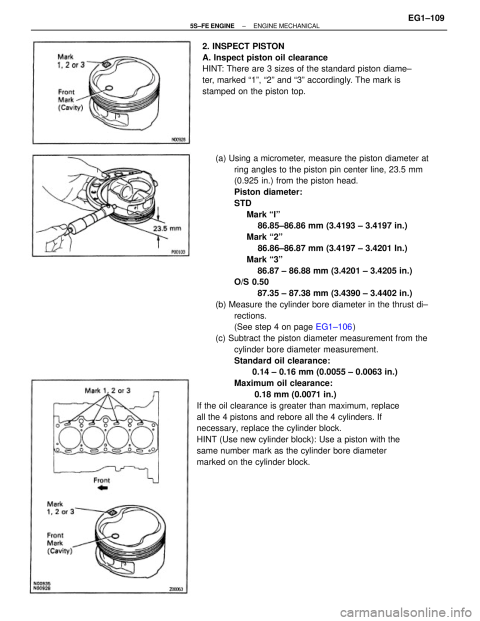
(a) Using a micrometer, measure the piston diameter at
ring angles to the piston pin center line, 23.5 mm
(0.925 in.) from the piston head.
Piston diameter:
STD
Mark ªIº
86.85±86.86 mm (3.4193 ± 3.4197 in.)
Mark ª2º
86.86±86.87 mm (3.4197 ± 3.4201 In.)
Mark ª3º
86.87 ± 86.88 mm (3.4201 ± 3.4205 in.)
O/S 0.50
87.35 ± 87.38 mm (3.4390 ± 3.4402 in.)
(b) Measure the cylinder bore diameter in the thrust di±
rections.
(See step 4 on page EG1±106)
(c) Subtract the piston diameter measurement from the
cylinder bore diameter measurement.
Standard oil clearance:
0.14 ± 0.16 mm (0.0055 ± 0.0063 in.)
Maximum oil clearance:
0.18 mm (0.0071 in.)
If the oil clearance is greater than maximum, replace
all the 4 pistons and rebore all the 4 cylinders. If
necessary, replace the cylinder block.
HINT (Use new cylinder block): Use a piston with the
same number mark as the cylinder bore diameter
marked on the cylinder block.2. INSPECT PISTON
A. Inspect piston oil clearance
HINT: There are 3 sizes of the standard piston diame±
ter, marked ª1º, ª2º and ª3º accordingly. The mark is
stamped on the piston top.
± 5S±FE ENGINEENGINE MECHANICALEG1±109
Page 160 of 4770

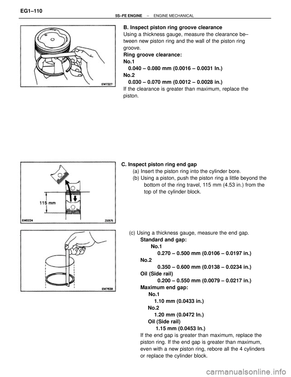
(c) Using a thickness gauge, measure the end gap.
Standard and gap:
No.1
0.270 ± 0.500 mm (0.0106 ± 0.0197 in.)
No.2
0.350 ± 0.600 mm (0.0138 ± 0.0234 in.)
Oil (Side rail)
0.200 ± 0.550 mm (0.0079 ± 0.0217 in.)
Maximum end gap:
No.1
1.10 mm (0.0433 in.)
No.2
1.20 mm (0.0472 In.)
Oil (Side rail)
1.15 mm (0.0453 In.)
If the end gap is greater than maximum, replace the
piston ring. If the end gap is greater than maximum,
even with a new piston ring, rebore all the 4 cylinders
or replace the cylinder block. B. Inspect piston ring groove clearance
Using a thickness gauge, measure the clearance be±
tween new piston ring and the wall of the piston ring
groove.
Ring groove clearance:
No.1
0.040 ± 0.080 mm (0.0016 ± 0.0031 In.)
No.2
0.030 ± 0.070 mm (0.0012 ± 0.0028 in.)
If the clearance is greater than maximum, replace the
piston.
C. Inspect piston ring end gap
(a) Insert the piston ring into the cylinder bore.
(b) Using a piston, push the piston ring a little beyond the
bottom of the ring travel, 115 mm (4.53 in.) from the
top of the cylinder block.
± 5S±FE ENGINEENGINE MECHANICALEG1±110
Page 161 of 4770
3. INSPECT CONNECTING ROD
A. Inspect connecting rod alignment
Using a rod aligner and thickness gauge, check the
connecting rod alignment.
wCheck for bend.
Maximum bend:
0.05 mm (0.0020 in.) per 100 mm (3.94 In.)
If bend is greater than maximum, replace the connect±
ing rod assembly.
wCheck for twist
Maximum twist:
0.15 mm (0.0059 in.) per 100 mm (3.94 in.)
If twist is greater than maximum, replace the connect±
ing rod assembly.
B. Inspect piston pin oil clearance
(a) Using a caliper gauge, measure the inside diameter of
the connecting rod bushing.
Bushing inside diameter:
22.005 ± 22.017 mm (0.8663 ± 0.8668 in.) D. Inspect±piston pin fit
At 60�C (140� F), you should be able to push the
piston pin into the piston pin hole with your thumb.
(b) Using a micrometer, measure the piston pin diameter.
Piston pin diameter:
21.997 ± 22.009 mm (0.8660 ± 0.8865 in.)
± 5S±FE ENGINEENGINE MECHANICALEG1±111
Page 162 of 4770
(c) Subtract the piston pin diameter measurement from
the bushing inside diameter measurement.
Standard oil clearance:
0.005 ± 0.011 mm (0.0002 ± 0.0004 in.)
Maximum oil clearance:
0.05 mm (0.0020 In.)
If the oil clearance is greater than maximum, replace
the bushing. If necessary, replace the piston and
piston pin as a set.
(b) Align the oil holes of a new bushing and the connect±
ing rod.
(c) Using SST and a press, press in the bushing.
SST 09222±30010
(e) Check the piston pin fit at normal room temperature.
Coat the piston pin with engine oil, and push it into the
connecting rod with your thumb. (d) Using a pin hole grinder, hone the bushing to obtain
the standard specified clearance (see step B above)
between the bushing and piston pin. C. If necessary, replace connecting rod bushing
(a) Using SST and a press, press out the bushing.
SST 09222 ± 30010
± 5S±FE ENGINEENGINE MECHANICALEG1±112
Page 165 of 4770

CRANKSHAFT INSPECTION AND REPAIR
1. INSPECT CRANKSHAFT FOR RUNOUT
(a) Place the crankshaft on V±blocks.
(b) Using a dial indicator, measure the circle runout at the
center journal.
Maximum circle runout:
0.06 mm (0.0024 In.)
If the circle runout is greater than maximum, replace
the crankshaft.
2. INSPECT MAIN JOURNALS AND CRANK PINS
(a) Using a micrometer, measure the diameter of each
main journal and crank pin.
Main journal diameter:
STD size
54.988 ± 55.003 mm (2.1653±2.1655 in.)
U/S 0.25
54.745 ± 54.755 mm (2.1553±2.1557 in.)
Crank pin diameter:
STD size
51.985 ± 52.000 mm (2.0466±2.0472 in.)
U/S 0.25
51.745 ± 51.755 mm (2.0372±2.0376 in.)
If the diameter is not as specified, check the oil clear±
ance (See pages EG1±98 to 104). If necessary, grind
or replace the crankshaft.
(b) Check each main journal and crank pin for taper and
out±of±round as shown.
Maximum taper and out±of±round:
0.02 mm (0.0008 in.)
If the taper and out±of±round is greater than maxi±
mum, replace the crankshaft.
3. IF NECESSARY. GRIND AND HONE MAIN JOUR±
NALS AND/OR CRANK PINS
Grind and hone the main journals and/or crank pins to
the finished undersized diameter (See procedure in
step 2).
Install new main journal and/or crankshaft pin under±
sized bearings.
± 5S±FE ENGINEENGINE MECHANICALEG1±115