Page 70 of 4770

IDLE SPEED INSPECTION
1. INITIAL CONDITIONS
(a) Engine at normal operating temperature
(b) Air cleaner installed
(c) All pipes and hoses of air induction system connected
(d) All vacuum lines properly connected
(e) MFI/SFI system wiring connectors fully plugged
(f) All operating accessories switched OFF
(g) Ignition timing set correctly
(h) Transmission in neutral position
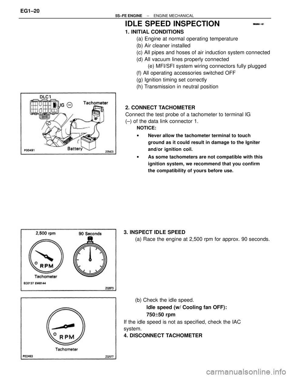
2. CONNECT TACHOMETER
Connect the test probe of a tachometer to terminal IG
(±) of the data link connector 1.
NOTICE:
wNever allow the tachometer terminal to touch
ground as it could result in damage to the Igniter
and/or ignition coil.
wAs some tachometers are not compatible with this
ignition system, we recommend that you confirm
the compatibility of yours before use.
(b) Check the idle speed.
Idle speed (w/ Cooling fan OFF):
750+50 rpm
If the idle speed is not as specified, check the IAC
system.
4. DISCONNECT TACHOMETER 3. INSPECT IDLE SPEED
(a) Race the engine at 2,500 rpm for approx. 90 seconds.
± 5S±FE ENGINEENGINE MECHANICALEG1±20
Page 73 of 4770

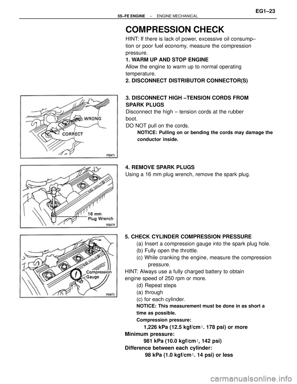
5. CHECK CYLINDER COMPRESSION PRESSURE
(a) Insert a compression gauge into the spark plug hole.
(b) Fully open the throttle.
(c) While cranking the engine, measure the compression
pressure.
HINT: Always use a fully charged battery to obtain
engine speed of 250 rpm or more.
(d) Repeat steps
(a) through
(c) for each cylinder.
NOTICE: This measurement must be done in as short a
time as possible.
Compression pressure:
1,226 kPa (12.5 kgf/cm�. 178 psi) or more
Minimum pressure:
981 kPa (10.0 kgf/cm�, 142 psi)
Difference between each cylinder:
98 kPa (1.0 kgf/cm�. 14 psi) or less
COMPRESSION CHECK
HINT: If there is lack of power, excessive oil consump±
tion or poor fuel economy, measure the compression
pressure.
1. WARM UP AND STOP ENGINE
Allow the engine to warm up to normal operating
temperature.
2. DISCONNECT DISTRIBUTOR CONNECTOR(S)
3. DISCONNECT HIGH ±TENSION CORDS FROM
SPARK PLUGS
Disconnect the high ± tension cords at the rubber
boot.
DO NOT pull on the cords.
NOTICE: Pulling on or bending the cords may damage the
conductor inside.
4. REMOVE SPARK PLUGS
Using a 16 mm plug wrench, remove the spark plug.
± 5S±FE ENGINEENGINE MECHANICALEG1±23
Page 74 of 4770
(e) If the cylinder compression in one or more cylinders is
low, pour a small amount of engine oil into the cylin±
der through the spark plug hole and repeat steps (a)
through
(c) for cylinders with low compression.
wIf adding oil helps the compression, chances are
that the piston rings and/or cylinder bore are
worn or damaged.
wIf pressure stays low, a valve may be sticking or
seating is improper, or there may be leakage past
the gasket.
6. REINSTALL SPARK PLUGS
Using a 16 mm plug wrench, install the spark plug.
Torque: 18 N±m (180 kgf±cm, 13 ft±lbf)
7. RECONNECT HIGH±TENSION CORDS TO SPARK
PLUGS
8. RECONNECT DISTRIBUTOR CONNECTOR(S)
± 5S±FE ENGINEENGINE MECHANICALEG1±24
Page 81 of 4770
TIMING BELT COMPONENTS INSPECTION
1. INSPECT TIMING BELT
NOTICE:
wDo not bend, twist or turn the timing belt Inside out.
wDo not allow the timing belt to come into contact
with oil, water or steam.
22. REMOVE CRANKSHAFT TIMING PULLEY
If the pulley cannot be removed by hand, use 2 screw±
drivers.
HINT: Position shop rags as shown to prevent
damage.20. REMOVE NO.1 IDLER PULLEY AND TENSION
SPRING
Remove the bolt, pulley and tension spring.
23. REMOVE OIL PUMP PULLEY
Using SST, remove the nut and pulley.
SST 09616±3001121. REMOVE NO.2 IDLER PULLEY
Remove the bolt and pulley.
± 5S±FE ENGINEENGINE MECHANICALEG1±31
Page 83 of 4770
3. INSPECT TENSION SPRING
(a) Measure the free length of tension spring.
Free length:
46.0 mm (1.811 in.)
If the free length is not as specified, replace the
tension spring.
(b) Measure the tension of the tension spring at the
specified installed length.
Installed tension (at 50.5 mm (1.988 in.)):
Green color
32 ± 37 N (3.25 ± 3.75 k9f, 7.2 ± 8.3 lbf)
Silver color
47 ± 52 N (4.75 ± 5.25 kgf, 10.5 ± 11.8 lbf)
If the installed tension is not as specified, replace the
tension spring.
TIMING BELT INSTALLATION
(See Components for Removal and Installation)
1. INSTALL OIL PUMP PULLEY
(a) Align the cutouts of the pulley and shaft, and slide on
the pulley. 2. INSPECT IDLER PULLEYS
Check that the idler pulley turns smoothly.
If necessary, replace the idler pulley.
(b) Using SST, install the nut.
SST 09616 ± 30011
Torque: 28 N±m (290 kgf±cm, 21 ft±lbf)
± 5S±FE ENGINEENGINE MECHANICALEG1±33
Page 84 of 4770

4. TEMPORARILY INSTALL NO.1 IDLER PULLEY AND
TENSION SPRING
(a) Install the pulley with the bolt. Do not tighten the bolt
yet.
HINT: Use a bolt 42 mm (1.65 in.) in length.
(b) Install the tension spring.
(c) Pry the pulley toward the left as far as it will go and
tighten the bolt.
(d) Check that the idler pulley moves smoothly.
5. TEMPORARILY INSTALL TIMING BELT
NOTICE: The engine should be cold.
(a) Using the crankshaft pulley bolt, turn the crankshaft
and position the key groove of the crankshaft timing
pulley upward.
(b) Remove any oil or water on the crankshaft pulley, oil
pump pulley, water pump pulley, No. 1 idler pulley, No.
2 idler pulley and keep them clean.
(c) Install the timing belt on the crankshaft timing pulley,
oil pump pulley, No.1 idler pulley, water pump pulley
and No.2 idler pulley.
HINT (When re±using timing belt): Align the points
marked during removal, and install the belt with the
arrow pointing in the direction of engine revolution. 2. INSTALL CRANKSHAFT TIMING PULLEY
(a) Align the timing pulley set key with the key groove of
the pulley.
(b) Slide on the timing pulley, facing the flange side
inward.
3. INSTALL NO.2 IDLER PULLEY
(a) Install the pulley with the bolt.
Torque: 42 N±m (425 kgf±cm, 31 ft±lbf)
HINT: Use a bolt 35 mm (1.38 in.) in length.
(b) Check that the idler pulley moves smoothly.
± 5S±FE ENGINEENGINE MECHANICALEG1±34
Page 86 of 4770
11. INSTALL TIMING BELT
HINT. (When re±using timing belt):
wCheck that the matchmark on the timing belt
matches the end of the No.1 timing belt cover.
If the matchmark does not align, shift the meshing of
the timing belt and crankshaft timing pulley until they
align. (See page EG1±29)
(a) Remove any oil or water on the camshaft timing
pulley, and keep it clean.
(b) Install the timing belt, and check the tension between
the crankshaft timing pulley and camshaft timing
pulley. (b) Using SST, turn the camshaft, and align the hole of
the camshaft timing pulley with the timing mark of the
bearing cap.
SST 09278±54012
wAlign the matchmarks of the timing belt and
camshaft timing pulley.
12. CHECK VALVE TIMING
(a) Loosen the No.1 idler pulley bolt 1/2 turn.
± 5S±FE ENGINEENGINE MECHANICALEG1±36
Page 94 of 4770
11. DISCONNECT OIL PRESSURE SWITCH
CONNECTOR
12. DISCONNECT ENGINE WIRE (FOR OXYGEN
SENSORS) FROM ENGINE HANGER
13. REMOVE WATER OUTLET
(a) Disconnect the following connectors:
(1) Engine coolant temperature sender gauge con±
nector
(2) Engine coolant temperature sensor connector
(b) Disconnect the following hoses:
(1) Upper radiator hose
(2) Water bypass pipe hose
(3) Heater water hose
(4) IAC water bypass hose
(5) 2 TVV (for EVAP) vacuum hoses
14. REMOVE WATER BYPASS PIPE
(a) Disconnect the following hoses:
(1) IAC water bypass hose
(2) Heater water hose
(3) w/ Oil Cooler:
2 oil cooler water bypass hoses (5) 3 bolts and 2 nuts
(6) Exhaust manifold
(7) Gasket
(8) Retainer
(9) Cushion
(10) WU±TWC
(c) Remove the 2 bolts, water outlet and gasket.
± 5S±FE ENGINEENGINE MECHANICALEG1±44