Page 130 of 4770
31. ASSEMBLE EXHAUST MANIFOLD AND WARM UP
THREE±WAY CATALYTIC CONVERTER
Assemble the following parts:
(1) WU±TWC
(2) Cushion
(3) Retainer
(4) Gasket
(5) Exhaust manifold
(6) 3 bolts and 2 nuts
Torque: 29 N±m (300 kgf±cm, 22 ft±lbf)
(c) Connect the following connectors:
(1) Engine coolant temperature sender gauge con±
nector
(2) Engine coolant temperature sensor connector
29. CONNECT ENGINE WIRE (FOR OXYGEN SENSORS)
TO ENGINE HANGER
30. CONNECT OIL PRESSURE SWITCH CONNECTOR
32. INSTALL EXHAUST MANIFOLD AND WARM UP
THREE±WAY CATALYTIC CONVERTER
ASSEMBLY
(a) Install a new gasket, the exhaust manifold and WU ±
TWC assembly with the 6 nuts. Uniformly tighten the
nuts in several passes.
Torque: 49 N±m (540 kgf±cm, 36 ft±lbf)
(7) 2 converter heat insulators
(8) 8 bolts
(9) Manifold lower heat insulator
(10) 3 bolts
± 5S±FE ENGINEENGINE MECHANICALEG1±80
Page 132 of 4770
37. A/T:
CONNECT AND ADJUST THROTTLE CABLE
38. CONNECT AND ADJUST ACCELERATOR CABLE
39. FILL WITH ENGINE COOLANT
Capacity:
6.3 liters (6.7 US qts, 5.5 Imp. qts)
40. CONNECT NEGATIVE (±) TERMINAL CABLE TO
BATTERY
41. START ENGINE AND CHECK FOR LEAKS
42. ADJUST IGNITION TIMING
(See page IG ±19 and 38)
Ignition timing:
10� BTDC @ idle
(w/ Terminals TO and E1 connected)
43. PERFORM ROAD TEST
Check for abnormal noise, shock, slippage, correct shift
points and smooth operation.
44. RECHECK ENGINE COOLANT LEVEL AND OIL
LEVEL
± 5S±FE ENGINEENGINE MECHANICALEG1±82
Page 135 of 4770

ENGINE REMOVAL
1. DISCONNECT NEGATIVE (±) TERMINAL CABLE
FROM BATTERY
CAUTION: Work must be started after 90 seconds from
the time the ignition switch is turned to the 'LOCK'
position and the negative (±) terminal cable Is discon±
nected from the battery.
2. REMOVE BATTERY AND TRAY
3. REMOVE HOOD
4. REMOVE ENGINE UNDER COVER
5. DRAIN ENGINE COOLANT
6. DRAIN ENGINE OIL
7. DISCONNECT ACCELERATOR CABLE FROM
THROTTLE BODY
8. A/T:
DISCONNECT THROTTLE CABLE FROM
THROTTLE BODY
9. REMOVE AIR CLEANER ASSEMBLY, RESONATOR
AND AIR CLEANER HOSE
(a) Disconnect the intake air temperature sensor connec±
tor.
(b) California only:
Disconnect the air hose from the air cleaner hose.
(c) Loosen the air cleaner hose clamp bolt.
(d) Disconnect the 4 air cleaner cap clips.
(e) Disconnect the air cleaner hose from the throttle
body, and remove the air cleaner cap together with
the resonator and air cleaner hose.
(f) Remove the element.
(g) Remove the 3 bolts and air cleaner case.
10. w/ CRUISE CONTROL SYSTEM:
REMOVE CRUISE CONTROL ACTUATOR
(a) Remove the actuator cover.
(b) Disconnect the actuator connector.
(c) Remove the 3 bolts, and disconnect the actuator with
the bracket.
11. REMOVE RADIATOR
± 5S±FE ENGINEENGINE MECHANICALEG1±85
Page 136 of 4770
(c) Disconnect the following connectors:
(1) Igniter connector
(2) California only:
Ignition coil connector
(3) Noise filter connector
(4) 2 ground straps from LH fender apron
(5) Connector from LH fender apron 12. DISCONNECT WIRES AND CONNECTORS
(a) Remove the engine relay box, and disconnect the 5
connectors.
(b) Connector from LH fender apron
(6) Data link connector 1
(7) 2 ground straps from RH fender apron
(d) Disconnect the MAP sensor connector.
13. DISCONNECT HEATER HOSES
14. DISCONNECT FUEL RETURN HOSE
CAUTION: Catch leaking fuel in a container.
± 5S±FE ENGINEENGINE MECHANICALEG1±86
Page 143 of 4770
9. REMOVE TIMING BELT AND PULLEYS
10. REMOVE CYLINDER HEAD
11. REMOVE WATER PUMP AND GENERATOR
ADJUSTING BAR
12. REMOVE OIL PAN AND OIL PUMP
13. REMOVE OIL FILTER
14. w/ OIL COOLER:
REMOVE OIL COOLER 4. REMOVE REAR END PLATE
Remove the bolt and end plate.
5. INSTALL ENGINE TO ENGINE STAND FOR
DISASSEMBLY
6. REMOVE GENERATOR
7. REMOVE DISTRIBUTOR1. M/T:
REMOVE CLUTCH COVER AND DISC
2. M/T:
REMOVE FLYWHEEL
3. A/T:
REMOVE DRIVE PLATE
15. REMOVE KNOCK SENSOR
Using SST, remove the knock sensor.
SST 09816 ± 300108. REMOVE PS PUMP BRACKET
Remove the 3 bolts and PS pump bracket.
PREPARATION FOR DISASSEMBLY
± 5S±FE ENGINEENGINE MECHANICALEG1±93
Page 144 of 4770

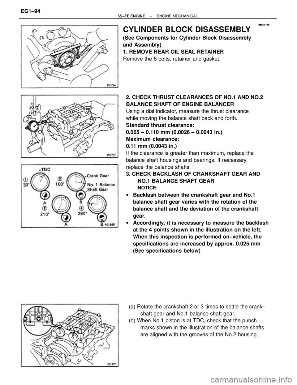
2. CHECK THRUST CLEARANCES OF NO.1 AND NO.2
BALANCE SHAFT OF ENGINE BALANCER
Using a dial indicator, measure the thrust clearance
while moving the balance shaft back and forth.
Standard thrust clearance:
0.065 ± 0.110 mm (0.0026 ± 0.0043 in.)
Maximum clearance:
0.11 mm (0.0043 in.)
If the clearance is greater than maximum, replace the
balance shaft housings and bearings. If necessary,
replace the balance shafts.
3. CHECK BACKLASH OF CRANKSHAFT GEAR AND
NO.1 BALANCE SHAFT GEAR
NOTICE:
wBacklash between the crankshaft gear and No.1
balance shaft gear varies with the rotation of the
balance shaft and the deviation of the crankshaft
gear.
wAccordingly, it is necessary to measure the backlash
at the 4 points shown in the illustration on the left.
When this inspection is performed on±vehicle, the
specifications are increased by approx. 0.025 mm
(See specifications below)
CYLINDER BLOCK DISASSEMBLY
(See Components for Cylinder Block Disassembly
and Assembly)
1. REMOVE REAR OIL SEAL RETAINER
Remove the 6 bolts, retainer and gasket.
(a) Rotate the crankshaft 2 or 3 times to settle the crank±
shaft gear and No.1 balance shaft gear.
(b) When No.1 piston is at TDC, check that the punch
marks shown in the illustration of the balance shafts
are aligned with the grooves of the No.2 housing.
± 5S±FE ENGINEENGINE MECHANICALEG1±94
Page 148 of 4770
5. CHECK CONNECTING ROD THRUST CLEARANCE
Using a dial indicator, measure the thrust clearance
while moving the connecting rod back and forth.
Standard thrust clearance:
0.160 ± 0.312 mm (0.0063 ± 0.0123 in.)
Maximum thrust clearance:
0.36 mm (0.0138 in.)
If the thrust clearance is greater than maximum, re±
place the connecting rod assembly. If necessary, re±
place the crankshaft.
6. REMOVE CONNECTING ROD CAPS AND CHECK
OIL CLEARANCE
(a) Check the matchmarks on the connecting rod and cap
to ensure correct reassembly.
(c) Using a plastic±faced hammer, lightly tap the con±
necting rod bolts and lift off the connecting rod cap.
HINT: Keep the lower bearing inserted with the con±
necting rod cap.4. REMOVE ENGINE BALANCER
(a) Uniformly loosen and remove the 6 bolts in several
passes, in the sequence shown.
(b) Remove the engine balancer and spacers.
(b) Using SST, remove the connecting rod cap nuts.
SST 09011±38121
± 5S±FE ENGINEENGINE MECHANICALEG1±98
Page 150 of 4770

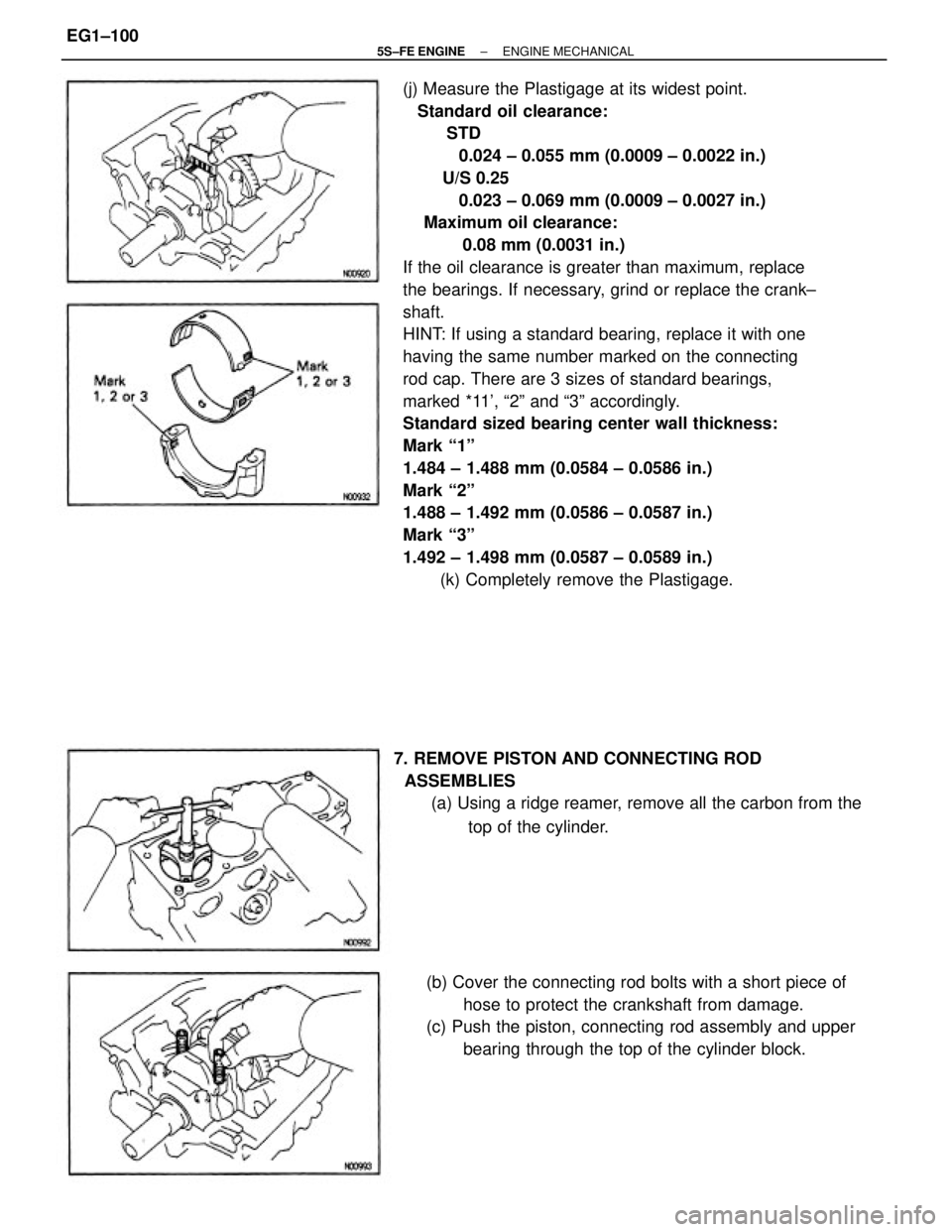
(j) Measure the Plastigage at its widest point.
Standard oil clearance:
STD
0.024 ± 0.055 mm (0.0009 ± 0.0022 in.)
U/S 0.25
0.023 ± 0.069 mm (0.0009 ± 0.0027 in.)
Maximum oil clearance:
0.08 mm (0.0031 in.)
If the oil clearance is greater than maximum, replace
the bearings. If necessary, grind or replace the crank±
shaft.
HINT: If using a standard bearing, replace it with one
having the same number marked on the connecting
rod cap. There are 3 sizes of standard bearings,
marked *11', ª2º and ª3º accordingly.
Standard sized bearing center wall thickness:
Mark ª1º
1.484 ± 1.488 mm (0.0584 ± 0.0586 in.)
Mark ª2º
1.488 ± 1.492 mm (0.0586 ± 0.0587 in.)
Mark ª3º
1.492 ± 1.498 mm (0.0587 ± 0.0589 in.)
(k) Completely remove the Plastigage.
(b) Cover the connecting rod bolts with a short piece of
hose to protect the crankshaft from damage.
(c) Push the piston, connecting rod assembly and upper
bearing through the top of the cylinder block. 7. REMOVE PISTON AND CONNECTING ROD
ASSEMBLIES
(a) Using a ridge reamer, remove all the carbon from the
top of the cylinder.
± 5S±FE ENGINEENGINE MECHANICALEG1±100