Page 981 of 4770

'99camry U
185
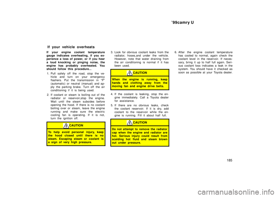
If your engine coolant temperature
gauge indicates overheating, if you ex-
perience a loss of power, or if you hear
a loud knocking or pinging noise, the
engine has probably overheated. You
should follow this procedure...
1. Pull safely off the road, stop the ve-
hicle and turn on your emergency
flashers. Put the transmission in ºPº
(automatic) or neutral (manual) and ap-
ply the parking brake. Turn off the air
conditioning if it is being used.
2. If coolant or steam is boiling out of the
radiator or reservoir,stop the engine.
Wait until the steam subsides before
opening the hood. If there is no coolant
boiling over or steam, leave the engine
running and make sure the electric
cooling fan is operating. If it is not,
turn the ignition off.
CAUTION
To help avoid personal injury, keep
the hood closed until there is no
steam. Escaping steam or coolant is
a sign of very high pressure.
3. Look for obvious coolant leaks from the
radiator, hoses,and under the vehicle.
However, note that water draining from
the air conditioning is normal if it has
been used.
CAUTION
When the engine is running, keep
hands and clothing away from the
moving fan and engine drive belts.
4. If the coolant is leaking, stop the en-
gine immediately. Call a Toyota dealer
for assistance.
5. If there are no obvious leaks, check
the coolant reservoir. If it is dry, add
coolant to the reservoir while the en-
gine is running. Fill it about half full.
CAUTION
Do not attempt to remove the radiator
cap when the engine and radiator are
hot. Serious injury could result from
scalding hot fluid and steam blown
out under pressure.
6. After the engine coolant temperature
has cooled to normal, again check the
coolant level in the reservoir. If neces-
sary, bring it up to half full again. Seri-
ous coolant loss indicates a leak in the
system. You should have it checked as
soon as possible at your Toyota dealer.
If your vehicle overheats
Page 1027 of 4770

CAMRY ± OUTLINE OF NEW FEATURES
CAMRY
26
OUTLINE OF NEW FEATURES
The Camry is a high-quality family sedan with advanced technology and sporty performance. The following
changes are made for the 1999 model year.
1. Model Line-Up
�The following models have been added.
SXV20L-AEMDKK, SXV20L-AEPDKK
MCV20L-CEMNKA, MCV20L-AEPDKK
�The following models have been discontinued.
SXV20L-CEMDKK, SXV20L-CEPDKK, SXV20L-CEMNKK, SXV20L-CEPNKK
MCV20L-CEMDKA, MCV20L-CEPDKK, MCV20L-CEPGKK
2. Engine
�ORVR (On-board Refueling Vapor Recovery) system has been adopted on the 1MZ-FE engine models.
The basic construction and operation of this system are the same as in the '98 Camry with 5S-FE Engine.
�The direction of the rotation of the radiator cooling fan of the 1MZ-FE engine models has been reversed.
�A service port has been provided for inspecting the evaporative emission control system on all models.
For details, see the General 1999 Features section.
3. Axles
The rear axle bearing specifications have been partially changed.
4. Brakes
The brake specifications have been partially changed.
5. Body
�The attachment method for the front bumper reinforcement has been changed.
�The center pillar garnish extends into the vehicle's interior to provide its effectiveness in absorbing the
energy in case the occupant's head collides against the pillar.
�A reinforcement has been added to the rocker panel to effectively dissipate the impact energy during a
frontal collision, thus minimizing the deformation of the cabin.
�The front, center and rear pillar garnishes provide an impact-absorbing structure consisting of internal ribs
that dampen the impact.
6. Seat
A seat fabric has been changed on the CE grade models to improve the seat appearance.
7. Seat Belt
The shape of the tongue plate has been changed to help improve the usability of the seat belt.
Page 1157 of 4770

B HOW TO USE THIS MANUAL
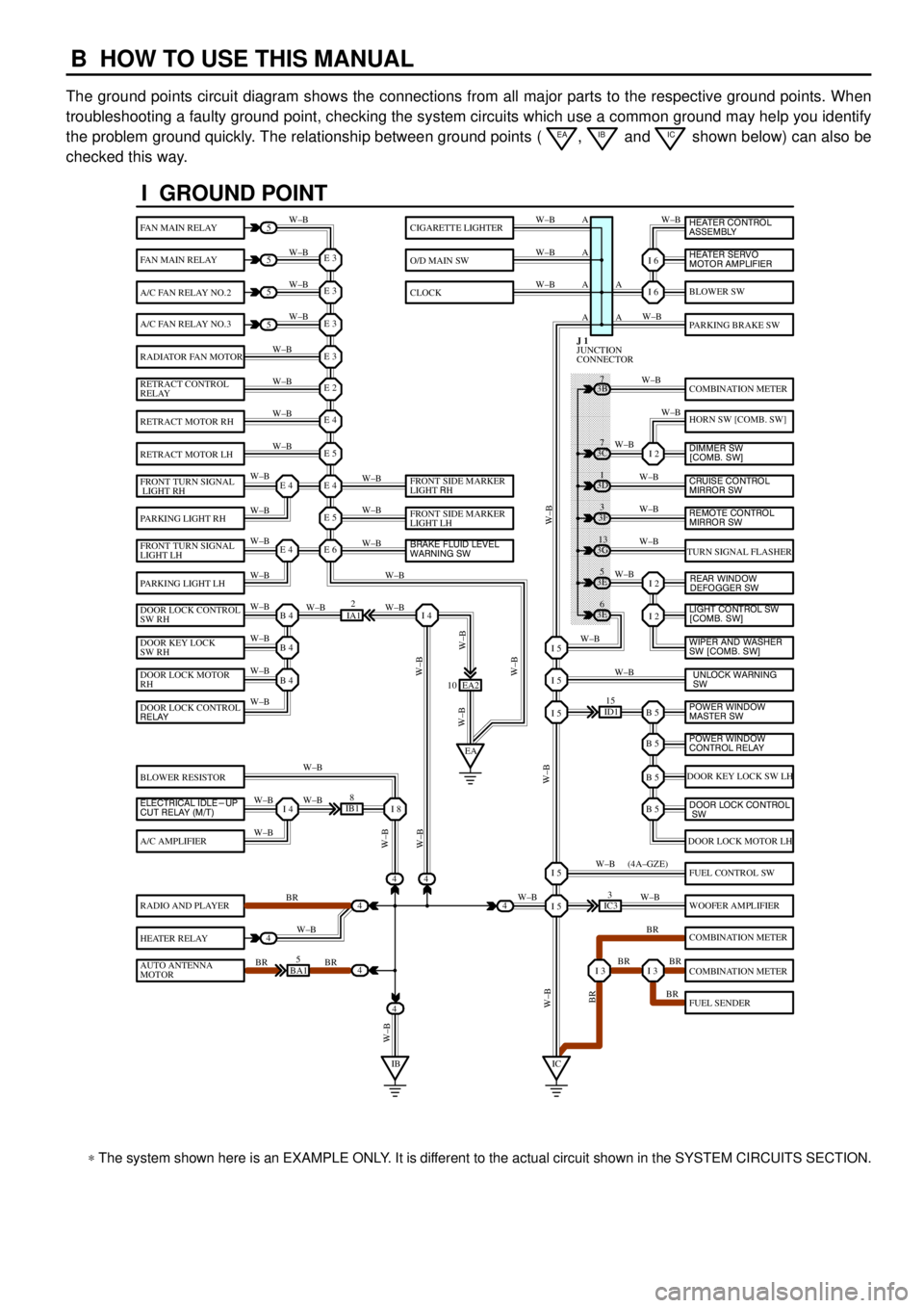
The ground points circuit diagram shows the connections from all major parts to the respective ground points. When
troubleshooting a faulty ground point, checking the system circuits which use a common ground may help you identify
the problem ground quickly. The relationship between ground points (
EA, IB and IC shown below) can also be
checked this way.
���� ���� ���� ���� ���� ���� ���� ���� ���� ���� ���� ���� ���� ���� ���� ���� ���� ���� ����
I GROUND POINT
FAN MAIN RELAY
FAN MAIN RELAY
A/C FAN RELAY NO.2
A/C FAN RELAY NO.3
RADIATOR FAN MOTOR
RETRACT CONTROL
RELAY
RETRACT MOTOR RH
RETRACT MOTOR LH
FRONT TURN SIGNAL
LIGHT RH
PARKING LIGHT RH
FRONT TURN SIGNAL
LIGHT LH
PARKING LIGHT LH
DOOR LOCK CONTROL
SW RH
DOOR KEY LOCK
SW RH
DOOR LOCK MOTOR
RH
BLOWER RESISTOR
A/C AMPLIFIER
RADIO AND PLAYER
HEATER RELAY
AUTO ANTENNA
MOTOR
BLOWER SW
PARKING BRAKE SW
COMBINATION METER
HORN SW [COMB. SW]
TURN SIGNAL FLASHER
DOOR KEY LOCK SW LH
DOOR LOCK MOTOR LH
FUEL CONTROL SW
WOOFER AMPLIFIER
COMBINATION METER
COMBINATION METER
FUEL SENDER
CIGARETTE LIGHTER
O/D MAIN SW
CLOCK
5
5
5
5
4
4
4
4
4BA15
IB18
EA2 10
3E5
3E
6 3G
13 3F
3 3D
1 3B
7
ID115
IC33
IA12
E 3
A
A AW±B
W±BW±B W±B
W±B W±B
W±B
W±B
W±B
W±B
W±B
W±B
W±B
W±B
W±B W±BW±B W±B W±B W±B
W±B W±B
W±BW±B
W±B
W±B
W±B W±B
W±B
BR
W±B
BR BRW±BW±B
W±B
W±B
W±B
W±B
W±B
W±B
W±B
W±B
W±B W±B
W±B
W±B
W±B
W±B
BR W±B
BR BR
BR W±B W±BW±B
W±BW±BBR W±B (4A±GZE)
W±B A A A
I 6
I 6
I 2
I 2
I 2
B 5I 5
I 5
I 5
B 5
B 5
B 5
I 5
I 5
I 3I 3
E 3
E 3
E 3
E 2
E 4
E 5
E 4
E 5
E 6E 4
E 4
B 4
EAI 4
B 4
B 4
I 4I 8
IBIC
3C7
4
JUNCTION
CONNECTOR J 1
4
DOOR LOCK CONTROL
RELAY
ELECTRICAL IDLE-UP
CUT RELAY (M/T)FRONT SIDE MARKER
LIGHT RH
FRONT SIDE MARKER
LIGHT LH
BRAKE FLUID LEVEL
WARNING SW
UNLOCK WARNING
SW WIPER AND WASHER
SW [COMB. SW] LIGHT CONTROL SW
[COMB. SW] HEATER CONTROL
ASSEMBLY
HEATER SERVO
MOTOR AMPLIFIER
DIMMER SW
[COMB. SW]
CRUISE CONTROL
MIRROR SW
REAR WINDOW
DEFOGGER SW
POWER WINDOW
MASTER SW
POWER WINDOW
CONTROL RELAY
DOOR LOCK CONTROL
SW
REMOTE CONTROL
MIRROR SW
* The system shown here is an EXAMPLE ONLY. It is different to the actual circuit shown in the SYSTEM CIRCUITS SECTION.
Page 1174 of 4770
F
3: Engine Room R/B No.3Radiator Upper Support RH (See Page 18)
(TMMK Made w/ ABS and Traction Control)
(TMC Made w/ ABS, w/ ABS and Traction Control)
3: Fusible Link BlockRadiator Upper Support RH (See Page 18)
(TMMK Made w/ ABS w/o Traction Control)
Page 1176 of 4770
G
Position of Parts in Engine Compartment
[1MZ±FE]
I 1 Idle Air Control Valve
I 2 Igniter
I 5 Ignition Coil No.1
I 6 Ignition Coil No.2
I 7 Ignition Coil No.3
I 8 Injector No.1
I 9 Injector No.2
I 10 Injector No.3
I 11 Injector No.4
I 12 Injector No.5
I 13 Injector No.6
K 1 Knock Sensor 1
K 2 Knock Sensor 2
M 2 Mass Air Flow Meter
N 1 Noise Filter (Ignition)
O 1 Oil Pressure SW
P 1 Park/Neutral Position SW,A/T Indicator Light SW and
Back±Up Light SW
P 2 Power Steering Oil Pressure SWR 1 Radiator Fan Motor
S 1 Starter
S 2 Starter
T 1 Theft Deterrent Horn
T 2 Throttle Position Sensor
V 2 Vehicle Speed Sensor (Combination Meter)
V 3 Vehicle Speed Sensor
(Electronically Controlled Transmission)
V 4 VSV (EGR)
V 5 VSV (EVAP)
V 6 VSV (Intake Air Control)
W 1 Washer Level Warning SW
W 2 Washer Motor
W 3 Water Temp. Sender
W 4 Water Temp. SW No.1
W 5 Water Temp. SW No.2
Page 1178 of 4770
G
Position of Parts in Engine Compartment
[5S±FE]
I 1 Idle Air Control Valve
I 3 Ignition Coil and Igniter No.1
I 4 Ignition Coil and Igniter No.2
I 8 Injector No.1
I 9 Injector No.2
I 10 Injector No.3
I 11 Injector No.4
I 14 Intake Air Temp. Sensor
K 1 Knock Sensor 1
M 1 Manifold Absolute Pressure Sensor
N 1 Noise Filter (Ignition)
O 1 Oil Pressure SW
P 1 Park/Neutral Position SW,A/T Indicator Light SW and
Back±Up Light SW
P 2 Power Steering Oil Pressure SWR 1 Radiator Fan Motor
S 1 Starter
S 2 Starter
T 1 Theft Deterrent Horn
T 2 Throttle Position Sensor
V 2 Vehicle Speed Sensor (Combination Meter)
V 4 VSV (EGR)
V 5 VSV (EVAP)
W 1 Washer Level Warning SW
W 2 Washer Motor
W 3 Water Temp. Sender
W 4 Water Temp. SW No.1
Page 1186 of 4770
G
Connector Joining Wire Harness and Wire Harness
12211234
56781 2 3 4
5 6 7 8
1234
56XX1 2 3 4
5 6 X X1112
3421
43
1
1
EA1DARK GRAYEB1GRAY
EB1GRAYEB2GRAYEC1DARK GRAY
ES1BLACK(w/ Daytime Running Light)
(w/o Daytime Running Light)
CodeJoining Wire Harness and Wire Harness (Connector Location)
EA1Engine Room Main Wire and Engine Room Main No.3 Wire (Radiator LH)
EB1Cowl Wire and Engine Room Main Wire (Under the Engine Room J/B No 2)EB2Cowl Wire and Engine Room Main Wire (Under the Engine Room J/B No.2)
EC1Engine Wire and Sensor Wire (Head Cover RH)
ES1Engine Wire and Engine Room Main Wire (Under the Engine Room J/B No.2)
Page 1188 of 4770
G
Connector Joining Wire Harness and Wire Harness
12211234
56781 2 3 4
5 6 7 8
1234
56XX1 2 3 4
5 6 X X11
EB1GRAY (w/ Daytime Running Light)EA1DARK GRAY
EB2GRAYEB1GRAY (w/o Daytime Running Light)
CodeJoining Wire Harness and Wire Harness (Connector Location)
EA1Engine Room Main Wire and Engine Room Main No.3 Wire (Radiator LH)
EB1Cowl Wire and Engine Room Main Wire (Under the Engine Room J/B No 2)EB2Cowl Wire and Engine Room Main Wire (Under the Engine Room J/B No.2)