Page 3986 of 4770
SS0AJ±03
SS±24
± SERVICE SPECIFICATIONSCOOLING (5S±FE)
187 Author�: Date�:
TORQUE SPECIFICATION
Part tightenedN´mkgf´cmft´lbf
Cylinder block x Drain plug2525018
Water pump x Water pump cover, Cylinder block8.89078 in.´lbf
Water bypass pipe x Water pump cover9.39582 in.´lbf
Generator drive belt adjusting bar x Cylinder block2222416
Water inlet x Water pump cover8.89078 in.´lbf
Oil cooler x Radiator lower tank8.38574 in.´lbf
Oil cooler pipe x Oil cooler14.715011
Upper radiator support x Body12.81309
Electric cooling fan x Radiator5.05044 in.´lbf
Page 3987 of 4770
SS07C±01
± SERVICE SPECIFICATIONSCOOLING (1MZ±FE)
SS±25
188 Author�: Date�:
COOLING (1MZ±FE)
SERVICE DATA
ThermostatValve opening pressure
Valve lift at 95°C (203°F)80 ± 84°C (176 ± 183°F)
10.0 mm (0.394 in.) or more
Radiator capRelief valve opening pressure STD
Minimum83 ± 113 kPa (0.85 ± 1.15 kgf/cm2, 12.1 ± 16.4 psi)
69 kPa (0.7 kgf/cm2, 10.0 psi)
RadiatorPlate height7.4 ± 7.8 mm (0.2959 ± 0.3119 in.)
Cooling fanRotating amperage at 20°C (68°F) No.1
No.28.3 ± 11.3 A
8.3 ± 11.3 A
Page 3988 of 4770
SS07D±02
SS±26
± SERVICE SPECIFICATIONSCOOLING (1MZ±FE)
189 Author�: Date�:
TORQUE SPECIFICATION
Part tightenedN´mkgf´cmft´lbf
RH engine drain plug x EGR cooler77061 in.´lbf
LH engine drain plug x Union on cylinder block131309
Water pump x Cylinder block88069 in.´lbf
Water inlet x Water inlet housing88069 in.´lbf
Water inlet pipe x LH cylinder head19.520014
Radiator support x Body12.81309
No.1 cooling fan shroud x Radiator5.05044 in.´lbf
No.2 cooling fan shroud x Radiator5.05044 in.´lbf
Radiator oil cooler x Radiator lower tank8.38574 in.´lbf
Radiator inlet pipe x Radiator lower tank14.715011
Page 4166 of 4770

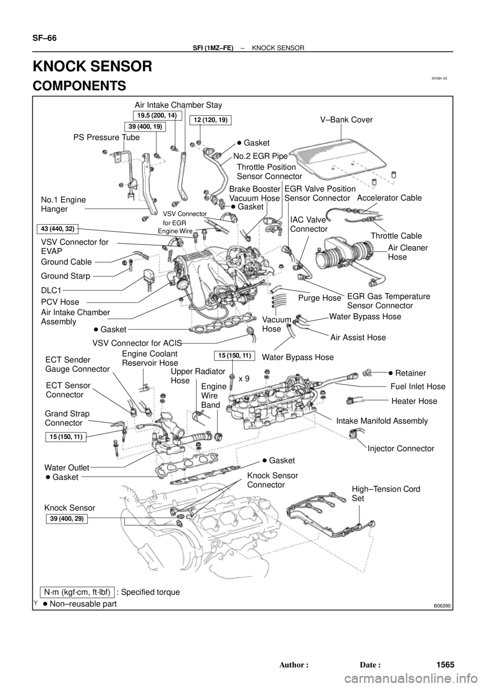
SF08K±03
B06390
VSV Connector for
EVAP
Ground Cable
PCV Hose
Air Intake Chamber
Assembly
ECT Sensor
Connector ECT Sender
Gauge ConnectorEGR Valve Position
Sensor Connector
IAC Valve
Connector
VSV Connector
for EGR
VSV Connector for ACIS
Engine Wire
Engine Coolant
Reservoir HoseAir Assist Hose
Water Bypass Hose No.2 EGR Pipe
Throttle Position
Sensor Connector
No.1 Engine
HangerBrake Booster
Vacuum Hose Air Intake Chamber Stay
Water OutletPS Pressure Tube
�Gasket
19.5 (200, 14)
39 (400, 19)12 (120, 19)
15 (150, 11)
�Gasket
43 (440, 32)
Ground Starp
DLC1
�Gasket
15 (150, 11)
Grand Strap
Connector
�Gasket
39 (400, 29)
V±Bank Cover
Accelerator Cable
Throttle Cable
Air Cleaner
Hose
Purge HoseEGR Gas Temperature
Sensor Connector
Vacuum
HoseWater Bypass Hose
Fuel Inlet Hose
Heater Hose
Intake Manifold Assembly
Injector Connector x 9
Knock Sensor
Connector
Upper Radiator
Hose
Engine
Wire
Band
High±Tension Cord
Set �Gasket
: Specified torque
�Non±reusable partN´m (kgf´cm, ft´lbf)
�Retainer
Knock Sensor
SF±66
± SFI (1MZ±FE)KNOCK SENSOR
1565 Author�: Date�:
KNOCK SENSOR
COMPONENTS
Page 4645 of 4770

WARRANTY PARTS MARKING PROCEDURE ± PG006-03September 26, 2003
Page 2 of 3
Dealers are requested to mark the location of the failure of all warranty parts that are
listed below.
This list is not inclusive. There may be other components that can be
marked in the area of failure. All other parts that can be marked should be marked.
assist grip assy headlamps
audio (blemish) headliner
back door garnish hoses
bumper covers instrument panel safety pad sub±assy
cargo cover (retractable) Interior light assemblies and covers
carpet knobs, levers, handles
clutch disc l/pulley pump assy
clutch flywheel mirrors (side and rearview)
combination meter glass navigation or VES screens
console and components pillar garnish
cowl assy rack and pinion/power steering gear assy
cowl side trim sub±assy radiator
cupholders room partition board
cylinder head cover sub±assy rotors (mark where min. runout is exceeded or warped)
dash panel insulator assy seat covers/cushions
dashboard and trim seat tracks
disc wheel soft trim
display panels spare tire cover
door handle assy steering column cover
door moulding steering wheel
door trim panel & molding tail lamps and covers
emblems transmission oil pan
engine oil pan visor
exhaust manifold washer jar
floor and cargo mats wheel cap
gear shift knob wheels
grills
Parts
Marking
Requirement
Parts
Marking
List
Page 4708 of 4770

TRANSMISSION OIL COOLER INSTALLATION ± TC003±97 October 17, 1997
ProcedureD. Remove the lower side clip of the
(Continued) radiator side LH deflector.
E. Install the tube bracket with the bolt
on the side member.
Torque: 62 in±lbf
(7 N±m / 71 kgf±cm)
F. Reinstall the lower side clip
of the radiator LH deflector.
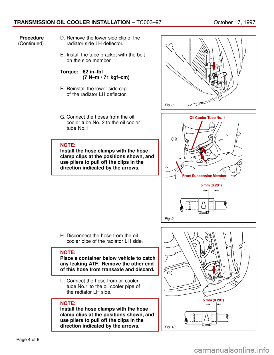
G. Connect the hoses from the oil
cooler tube No. 2 to the oil cooler
tube No.1.
NOTE:
Install the hose clamps with the hose
clamp clips at the positions shown, and
use pliers to pull off the clips in the
direction indicated by the arrows.
H. Disconnect the hose from the oil
cooler pipe of the radiator LH side.
NOTE:
Place a container below vehicle to catch
any leaking ATF. Remove the other end
of this hose from transaxle and discard.
I. Connect the hose from oil cooler
tube No.1 to the oil cooler pipe of
the radiator LH side.
NOTE:
Install the hose clamps with the hose
clamp clips at the positions shown, and
use pliers to pull off the clips in the
direction indicated by the arrows.
Page 4 of 6
Fig. 8
Oil Cooler Tube No. 1
Front Suspension Member
5 mm (0.20º)
Fig. 9
Fig. 10
5 mm (0.20º)