Page 3510 of 4770
VALVE CLEARANCE
1290 Author�: Date�:
VALVE CLEARANCE
INSPECTION
HINT:
Inspect and adjust the val")
EM04K±04
P18805
P13074
RH EX
RH IN
LH IN
LH EX 13
6
23
1
6
2Front EM±4
± ENGINE MECHANICAL (1MZ±FE)VALVE CLEARANCE
1290 Author�: Date�:
VALVE CLEARANCE
INSPECTION
HINT:
Inspect and adjust the valve clearance when the engine is cold.
1. REMOVE RH FENDER APRON SEAL
2. DRAIN ENGINE COOLANT
3. REMOVE V±BANK COVER
(a) Using a 5 mm hexagon wrench, remove the 2 nuts.
(b) Disconnect the 2 clips, and remove the cover.
4. REMOVE HIGH±TENSION CODE SET
(See page IG±7)
5. REMOVE AIR INTAKE CHAMBER ASSEMBLY
(See page EM±32)
6. REMOVE IGNITION COILS
7. DISCONNECT RADIATOR HOSE FROM WATER
OUTLET
8. REMOVE CYLINDER HEAD COVERS
(See page EM±32)
9. SET NO.1 CYLINDER TO TDC/COMPRESSION
(a) Turn the crankshaft pulley, and align its groove with the
timing mark º0º of the No.1 timing belt cover.
(b) Check that the valve lifters on the No.1 (IN and EX) are
loose.
If not, turn the crankshaft 1 revolution (360°) and align the mark
as above.
10. INSPECT VALVE CLEARANCE
(a) Check only those valves indicated in the illustration.
(1) Using a feeler gauge, measure the clearance be-
tween the valve lifter and camshaft.
(2) Record out of specification valve clearance mea-
surements. They will be used later to determine the
required replacement adjusting shim.
Valve clearance (Cold):
Intake0.15 ± 0.25 mm (0.006 ± 0.010 in.)
Exhaust0.25 ± 0.35 mm (0.010 ± 0.014 in.)
Page 3513 of 4770
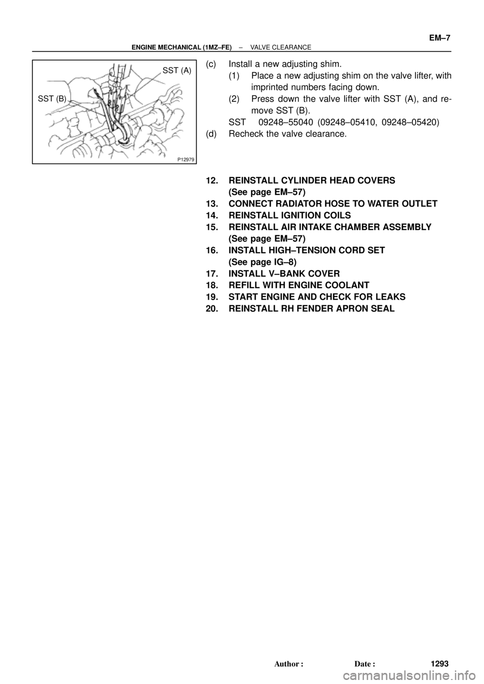
P12979
SST (A)
SST (B)
± ENGINE MECHANICAL (1MZ±FE)VALVE CLEARANCE
EM±7
1293 Author�: Date�:
(c) Install a new adjusting shim.
(1) Place a new adjusting shim on the valve lifter, with
imprinted numbers facing down.
(2) Press down the valve lifter with SST (A), and re-
move SST (B).
SST 09248±55040 (09248±05410, 09248±05420)
(d) Recheck the valve clearance.
12. REINSTALL CYLINDER HEAD COVERS
(See page EM±57)
13. CONNECT RADIATOR HOSE TO WATER OUTLET
14. REINSTALL IGNITION COILS
15. REINSTALL AIR INTAKE CHAMBER ASSEMBLY
(See page EM±57)
16. INSTALL HIGH±TENSION CORD SET
(See page IG±8)
17. INSTALL V±BANK COVER
18. REFILL WITH ENGINE COOLANT
19. START ENGINE AND CHECK FOR LEAKS
20. REINSTALL RH FENDER APRON SEAL
Page 3534 of 4770

EGR Gas Temperature
Sensor Connector
Water Bypass Hose
A06657
PS Pressure TubeAir Intake Chamber Stay
V±Bank Cover
VSV Connector
for EGR
Engine Wire�Gasket
No.2 EGR Pipe
Throttle Position
Sensor Connector
Vacuum Hose
EGR Valve Position Brake Booster12 (120,9)
39 (400,29)
�Gasket
Sensor Connector
IAC Valve
ConnectorAccelerator Cable
Throttle Cable
Purge Hose
Air Assist Hose Hose Vacuum
�Gasket
VSV Connector for ACIS
Engine Coolant
Reservoir Hose
43 (440,32)
ECT Sender
Gauge Connector
ECT Sensor
Connector
Grand Strap
Connector
15 (150,11)
Water Outlet
15 (150,11)
Water Bypass
Hose
Upper Radiator
Hose
Fuel Inlet Hose
Injector Connector Intake Manifold Assembly�Retainer
Heater Hose
�Gasket Ignition Coil
Connector
� Non±reusable part: Specified torque
N´m (kgf´cm, ft´lbf)
19.5 (200, 14)
No.1 Engine
Hanger
VSV Connector for
EVAP
Ground Cable
PCV Hose Ground Cable
Air Intake Chamber
Assembly
� Gasket
High±Tension Cord Set
Spark PlugIgnition Coil
Water Bypass Hose
Ground Strap
DLC1
EM±28
± ENGINE MECHANICAL (1MZ±FE)CYLINDER HEAD
1314 Author�: Date�:
Page 3540 of 4770
CYLINDER HEAD
1320 Author�: Date�:
10. REMOVE WATER OUTLET
(a) Disconnect the ECT sender gauge connector.
(b) Disconne")
P20049Gasket
A05077
Clamp
Clamp
Clamp
S04786
EM±34
± ENGINE MECHANICAL (1MZ±FE)CYLINDER HEAD
1320 Author�: Date�:
10. REMOVE WATER OUTLET
(a) Disconnect the ECT sender gauge connector.
(b) Disconnect the ECT sensor connector.
(c) Disconnect the ground strap (connector).
(d) Disconnect the radiator hose.
(e) Disconnect the engine coolant reservoir hose.
(f) Remove the 2 bolts, 2 nuts and 2 plate washers.
(g) Disconnect the water bypass hose, and remove the water
outlet.
(h) Remove the 2 gaskets.
11. REMOVE GENERATOR DRIVE BELT
(See page CH±6)
12. REMOVE PS PUMP (See page SR±21)
13. REMOVE IGNITION COILS
14. REMOVE SPARK PLUGS
15. REMOVE TIMING BELT (See page EM±15)
16. REMOVE CAMSHAFT TIMING PULLEYS
(See page EM±15)
17. REMOVE NO.2 IDLER PULLEY (See page EM±15)
18. REMOVE NO.3 TIMING BELT COVER
(a) Disconnect the 3 engine wire clamps from the timing belt
cover.
(b) Remove the 6 bolts and timing belt cover.
19. DISCONNECT ENGINE WIRE PROTECTOR FROM
REAR SIDE
Remove the 2 nuts, and disconnect the engine wire protector
from the RH cylinder head and water inlet.
Page 3572 of 4770

L = 180 mm (7.09 in.)L = 72 mm (2.83 in.)
L = 335 mm (13.19 in.)L = 180 mm
(7.09 in.)
L = Length Join
LineJoin
Line
Z14262New Gasket
A01808
8
6
5
4
3
2
1
9
10
7
11
EM")
A05194
L = 133 mm (5.24 in.)
L = 180 mm (7.09 in.)L = 72 mm (2.83 in.)
L = 335 mm (13.19 in.)L = 180 mm
(7.09 in.)
L = Length Join
LineJoin
Line
Z14262New Gasket
A01808
8
6
5
4
3
2
1
9
10
7
11
EM±66
± ENGINE MECHANICAL (1MZ±FE)CYLINDER HEAD
1352 Author�: Date�: �
Remove the backing paper from a new gasket and
install the gasket evenly to the part of the timing belt
cover shaded black in the illustration.
NOTICE:
When joining 2 gaskets, do not leave a gap between them.
Cut off any excess gasket.
�After installing the gasket, press down on it so that
the adhesive firmly sticks to the timing belt cover.
(b) Install the timing belt cover with the 6 bolts.
Torque: 8.5 N´m (85 kgf´cm, 74 in.´lbf)
(c) Install the 3 engine wire clamps to the timing belt cover.
20. INSTALL NO.2 IDLER PULLEY (See page EM±21)
21. INSTALL CAMSHAFT TIMING PULLEYS
(See page EM±21)
22. INSTALL TIMING BELT (See page EM±21)
23. INSTALL SPARK PLUGS
24. INSTALL IGNITION COILS
25. INSTALL PS PUMP DRIVE BELT
26. INSTALL GENERATOR DRIVE BELT
(See page SR±28)
27. INSTALL WATER OUTLET
(a) Install 2 new gaskets.
(b) Connect the water outlet to the bypass hose.
(c) Install the water outlet with the 2 bolts, 2 nuts and 2 plate
washers. Alternately tighten the bolts and nuts.
Torque: 15 N´m (150 kgf´cm, 11 ft´lbf)
NOTICE:
Do not scratch the seal surface of the water outlet with the
stud bolt.
(d) Connect the ECT sender gauge connector.
(e) Connect the ECT sensor connector.
(f) Connect the ground strap (connector).
(g) Connect the radiator hose.
(h) Connect the engine coolant reservoir hose.
28. INSTALL INTAKE MANIFOLD ASSEMBLY
(a) Install the intake manifold, delivery pipe and injectors as-
sembly with the 9 bolts, 2 plate washers and 2 nuts. Uni-
formly tighten the bolts and nuts, in several passes, in the
sequence shown.
Torque: 15 N´m (150 kgf´cm, 11 ft´lbf)
Page 3575 of 4770

EM04X±04
A06650
No.2 Cooling Fan Connector
Upper Radiator Support
Radiator Assembly
RH Fender
Apron
Seal
Generator
Drive
Belt
A/C Compressor
ConnectorNo.1 ECT Switch
Wire Connector
Battery
Insulator
Battery
Battery
Tray Generator Drive
Belt Adjusting
Bar Bracket
LH Fender
Apron SealA/T
Oil Cooler
Hose
� Gasket A/C Compressor
43 (440, 32)
25 (250, 18)
�Non±reusable partStay
N´m (kgf´cm, ft´lbf)Bracket Front Exhaust Pipe: Specified torque� Gasket
62 (630, 46)
33 (330, 24)
�
62 (630, 46)
33 (330, 24)
� Gasket
56 (570, 41)
Actuator Cover
EGR Vacuum HoseUpper Radiator
Support
No.1 Cooling
Fan ConnectorHood
Hold±Down
Clamp
Washer
Hose for
Windshield
Air Filter
Air Cleaner Case
� O±Ring Lower Radiator Support
Drain
Plug
Lower Radiator
Support
Air Cleaner
Cap Assembly
Radiator Upper Hose
Cruise Control
Actuator
Cruise Control
Actuator
Connector
Accelerator Cable
PS Pump
Radiator Lower Hose
� PS Pump
Drive Belt
EVAP Hose
MAF Meter
Connector
± ENGINE MECHANICAL (1MZ±FE)ENGINE UNIT
EM±69
1355 Author�: Date�:
ENGINE UNIT
COMPONENTS
Page 3577 of 4770
ENGINE UNIT
EM±71
1357 Author�: Date�:
REMOVAL
1. REMOVE BATTERY AND TRAY
2. REMOVE HOOD
3. REMOVE ENGINE FENDER APRON SEALS
4. DRAIN ENGINE COOLANT
5.")
EM04Y±03
S05048
± ENGINE MECHANICAL (1MZ±FE)ENGINE UNIT
EM±71
1357 Author�: Date�:
REMOVAL
1. REMOVE BATTERY AND TRAY
2. REMOVE HOOD
3. REMOVE ENGINE FENDER APRON SEALS
4. DRAIN ENGINE COOLANT
5. DRAIN ENGINE OIL
6. DISCONNECT ACCELERATOR CABLE
7. REMOVE AIR CLEANER CAP ASSEMBLY AND AIR
CLEANER CASE
8. REMOVE CRUISE CONTROL ACTUATOR
9. REMOVE RADIATOR (See page CO±18)
10. REMOVE FRONT EXHAUST PIPE
(a) Remove the 2 bolts holding the support stay to the sup-
port bracket.
(b) Remove the 2 bolts holding the support bracket to the
front frame.
(c) Remove the 2 bolts and 2 nuts holding the front exhaust
pipe to the center exhaust pipe.
(d) Remove the 4 nuts holding the front exhaust pipe to the
exhaust manifolds.
(e) Remove the front exhaust pipe and 3 gaskets.
11. DISCONNECT CONNECTORS, CABLE, CLAMPS
AND HOSES
(a) Disconnect the igniter connector on the LH fender apron.
(b) Disconnect the noise filter connector on the LH fender
apron.
(c) Disconnect the generator wire and connector.
(d) Disconnect the starter wire and connector.
(e) Disconnect the 2 ground strap connectors from the LH
fender apron.
(f) Disconnect the 2 ground strap connectors from the RH
fender apron.
(g) Disconnect the ground cable from the battery body brack-
et.
(h) Disconnect the engine wire protector clamp from the bat-
tery body bracket.
(i) Disconnect the engine wire clamp from the bracket on the
RH fender apron.
(j) Disconnect the engine wire clamp from the bracket on the
fuel filter.
Page 3585 of 4770
ENGINE UNIT
EM±79
1365 Author�: Date�:
(f) Connect the 2 ground strap connectors to the LH fender
apron.
(g) Connect the DLC1 to the RH fender apron.
(h) Connect")
S05048
± ENGINE MECHANICAL (1MZ±FE)ENGINE UNIT
EM±79
1365 Author�: Date�:
(f) Connect the 2 ground strap connectors to the LH fender
apron.
(g) Connect the DLC1 to the RH fender apron.
(h) Connect the ground cable to the battery body bracket.
(i) Connect the engine wire protector clamp to the battery
body bracket.
(j) Connect the engine wire clamp to the bracket on the RH
fender apron.
(k) Connect the engine wire clamp to the bracket on the fuel
filter.
(l) Connect the brake booster vacuum hose to the air intake
chamber.
(m) Connect the engine coolant reservoir hose to the water
outlet.
(n) Connect the heater hose to the intake manifold.
(o) Connect the heater hose to the water inlet housing.
(p) Connect the fuel inlet hose to the fuel filter.
CAUTION:
Perform connecting operations of the fuel tube connector
(quick type) after observing the precautions.
(See page SF±6)
(q) Connect the purge hose to the pipe on the emission con-
trol valve set.
(r) Connect the 2 vacuum hoses to the vacuum tank for the
ACIS.
21. INSTALL FRONT EXHAUST PIPE
(a) Temporarily install 3 new gaskets and the front exhaust
pipe with the 2 bolts and 6 nuts.
(b) Tighten the 4 nuts holding the exhaust manifolds to the
front exhaust pipe.
Torque: 62 N´m (630 kgf´cm, 46 ft´lbf)
(c) Tighten the 2 bolts and 2 nuts holding the front exhaust
pipe to the center exhaust pipe.
Torque: 56 N´m (570 kgf´cm, 41 ft´lbf)
(d) Install the bracket with the 2 bolts.
Torque: 33 N´m (330 kgf´cm, 24 ft´lbf)
(e) Install the support stay with the 2 bolts.
Torque: 33 N´m (330 kgf´cm, 24 ft´lbf)
22. INSTALL RADIATOR (See page CO±24)
23. INSTALL CRUISE CONTROL ACTUATOR
24. INSTALL AIR CLEANER CAP ASSEMBLY AND AIR
CLEANER CASE
25. CONNECT ACCELERATOR CABLE
26. INSTALL ENGINE FENDER APRON SEALS
27. INSTALL BATTERY TRAY AND BATTERY