Page 3572 of 4770

L = 180 mm (7.09 in.)L = 72 mm (2.83 in.)
L = 335 mm (13.19 in.)L = 180 mm
(7.09 in.)
L = Length Join
LineJoin
Line
Z14262New Gasket
A01808
8
6
5
4
3
2
1
9
10
7
11
EM")
A05194
L = 133 mm (5.24 in.)
L = 180 mm (7.09 in.)L = 72 mm (2.83 in.)
L = 335 mm (13.19 in.)L = 180 mm
(7.09 in.)
L = Length Join
LineJoin
Line
Z14262New Gasket
A01808
8
6
5
4
3
2
1
9
10
7
11
EM±66
± ENGINE MECHANICAL (1MZ±FE)CYLINDER HEAD
1352 Author�: Date�: �
Remove the backing paper from a new gasket and
install the gasket evenly to the part of the timing belt
cover shaded black in the illustration.
NOTICE:
When joining 2 gaskets, do not leave a gap between them.
Cut off any excess gasket.
�After installing the gasket, press down on it so that
the adhesive firmly sticks to the timing belt cover.
(b) Install the timing belt cover with the 6 bolts.
Torque: 8.5 N´m (85 kgf´cm, 74 in.´lbf)
(c) Install the 3 engine wire clamps to the timing belt cover.
20. INSTALL NO.2 IDLER PULLEY (See page EM±21)
21. INSTALL CAMSHAFT TIMING PULLEYS
(See page EM±21)
22. INSTALL TIMING BELT (See page EM±21)
23. INSTALL SPARK PLUGS
24. INSTALL IGNITION COILS
25. INSTALL PS PUMP DRIVE BELT
26. INSTALL GENERATOR DRIVE BELT
(See page SR±28)
27. INSTALL WATER OUTLET
(a) Install 2 new gaskets.
(b) Connect the water outlet to the bypass hose.
(c) Install the water outlet with the 2 bolts, 2 nuts and 2 plate
washers. Alternately tighten the bolts and nuts.
Torque: 15 N´m (150 kgf´cm, 11 ft´lbf)
NOTICE:
Do not scratch the seal surface of the water outlet with the
stud bolt.
(d) Connect the ECT sender gauge connector.
(e) Connect the ECT sensor connector.
(f) Connect the ground strap (connector).
(g) Connect the radiator hose.
(h) Connect the engine coolant reservoir hose.
28. INSTALL INTAKE MANIFOLD ASSEMBLY
(a) Install the intake manifold, delivery pipe and injectors as-
sembly with the 9 bolts, 2 plate washers and 2 nuts. Uni-
formly tighten the bolts and nuts, in several passes, in the
sequence shown.
Torque: 15 N´m (150 kgf´cm, 11 ft´lbf)
Page 3575 of 4770

EM04X±04
A06650
No.2 Cooling Fan Connector
Upper Radiator Support
Radiator Assembly
RH Fender
Apron
Seal
Generator
Drive
Belt
A/C Compressor
ConnectorNo.1 ECT Switch
Wire Connector
Battery
Insulator
Battery
Battery
Tray Generator Drive
Belt Adjusting
Bar Bracket
LH Fender
Apron SealA/T
Oil Cooler
Hose
� Gasket A/C Compressor
43 (440, 32)
25 (250, 18)
�Non±reusable partStay
N´m (kgf´cm, ft´lbf)Bracket Front Exhaust Pipe: Specified torque� Gasket
62 (630, 46)
33 (330, 24)
�
62 (630, 46)
33 (330, 24)
� Gasket
56 (570, 41)
Actuator Cover
EGR Vacuum HoseUpper Radiator
Support
No.1 Cooling
Fan ConnectorHood
Hold±Down
Clamp
Washer
Hose for
Windshield
Air Filter
Air Cleaner Case
� O±Ring Lower Radiator Support
Drain
Plug
Lower Radiator
Support
Air Cleaner
Cap Assembly
Radiator Upper Hose
Cruise Control
Actuator
Cruise Control
Actuator
Connector
Accelerator Cable
PS Pump
Radiator Lower Hose
� PS Pump
Drive Belt
EVAP Hose
MAF Meter
Connector
± ENGINE MECHANICAL (1MZ±FE)ENGINE UNIT
EM±69
1355 Author�: Date�:
ENGINE UNIT
COMPONENTS
Page 3577 of 4770
ENGINE UNIT
EM±71
1357 Author�: Date�:
REMOVAL
1. REMOVE BATTERY AND TRAY
2. REMOVE HOOD
3. REMOVE ENGINE FENDER APRON SEALS
4. DRAIN ENGINE COOLANT
5.")
EM04Y±03
S05048
± ENGINE MECHANICAL (1MZ±FE)ENGINE UNIT
EM±71
1357 Author�: Date�:
REMOVAL
1. REMOVE BATTERY AND TRAY
2. REMOVE HOOD
3. REMOVE ENGINE FENDER APRON SEALS
4. DRAIN ENGINE COOLANT
5. DRAIN ENGINE OIL
6. DISCONNECT ACCELERATOR CABLE
7. REMOVE AIR CLEANER CAP ASSEMBLY AND AIR
CLEANER CASE
8. REMOVE CRUISE CONTROL ACTUATOR
9. REMOVE RADIATOR (See page CO±18)
10. REMOVE FRONT EXHAUST PIPE
(a) Remove the 2 bolts holding the support stay to the sup-
port bracket.
(b) Remove the 2 bolts holding the support bracket to the
front frame.
(c) Remove the 2 bolts and 2 nuts holding the front exhaust
pipe to the center exhaust pipe.
(d) Remove the 4 nuts holding the front exhaust pipe to the
exhaust manifolds.
(e) Remove the front exhaust pipe and 3 gaskets.
11. DISCONNECT CONNECTORS, CABLE, CLAMPS
AND HOSES
(a) Disconnect the igniter connector on the LH fender apron.
(b) Disconnect the noise filter connector on the LH fender
apron.
(c) Disconnect the generator wire and connector.
(d) Disconnect the starter wire and connector.
(e) Disconnect the 2 ground strap connectors from the LH
fender apron.
(f) Disconnect the 2 ground strap connectors from the RH
fender apron.
(g) Disconnect the ground cable from the battery body brack-
et.
(h) Disconnect the engine wire protector clamp from the bat-
tery body bracket.
(i) Disconnect the engine wire clamp from the bracket on the
RH fender apron.
(j) Disconnect the engine wire clamp from the bracket on the
fuel filter.
Page 3586 of 4770
EM±80
± ENGINE MECHANICAL (1MZ±FE)ENGINE UNIT
1366 Author�: Date�:
28. INSTALL HOOD
29. FILL ENGINE WITH OIL
30. FILL WITH ENGINE COOLANT
31. START ENGINE AND CHECK FOR LEAKS
32. PERFORM ROAD TEST
Check for abnormal noise, shock, slippage, correct shift points
and smooth operation.
33. RECHECK ENGINE COOLANT AND OIL LEVELS
Page 3587 of 4770

No.2 Idler Pulley Bracket
Water Seal Plate
Engine Cool")
EM050±03
A06640
Knock Sensor Connector
Engine Wire Band
Engine WireKnock Sensor
No.2 ECT Switch Connector
Water Inlet Housing
(With Water Inlet)
No.2 Idler Pulley Bracket
Water Seal Plate
Engine Coolant
Drain Union
Oil Filter Union
Oil Filter � Gasket
EGR Cooler
� Gasket
Water Pump
� Crankshaft
Front Oil Seal
Crankshaft
Position Sensor
Connector� Oil Pressure Switch
Oil Pressure Switch
ConnectorA/C Compressor
Housing Bracket
No.1 Oil Pan
x 15 or 17 Oil Pump
� Gasket
� Gasket
Engine Wire
Generator
Drain Plugx 10No.2 Oil Pan Oil Strainer
� Non±reusable part
N´m (kgf´cm, ft´lbf) : Specified torque
Precoated part �
x 8
�
� O±Ring
x 9
9 (90, 78 in.´lbf)
8 (80, 69 in.´lbf)
10mm Head 7.8 (80, 69 in.´lbf)
12mm Head 19.5 (200,14)
39 (400, 29)
28 (290, 21)
14.5 (145, 10)
25 (250, 18)
10mm Head 8 (80, 69 in.´lbf)
12mm Head 19.5 (200,14)
8 (80, 69 in.´lbf)
8 (80, 69 in.´lbf)45 (460, 33)
8 (80, 69 in.´lbf)
or 0 or 0
± ENGINE MECHANICAL (1MZ±FE)CYLINDER BLOCK
EM±81
1367 Author�: Date�:
CYLINDER BLOCK
COMPONENTS
Page 3588 of 4770
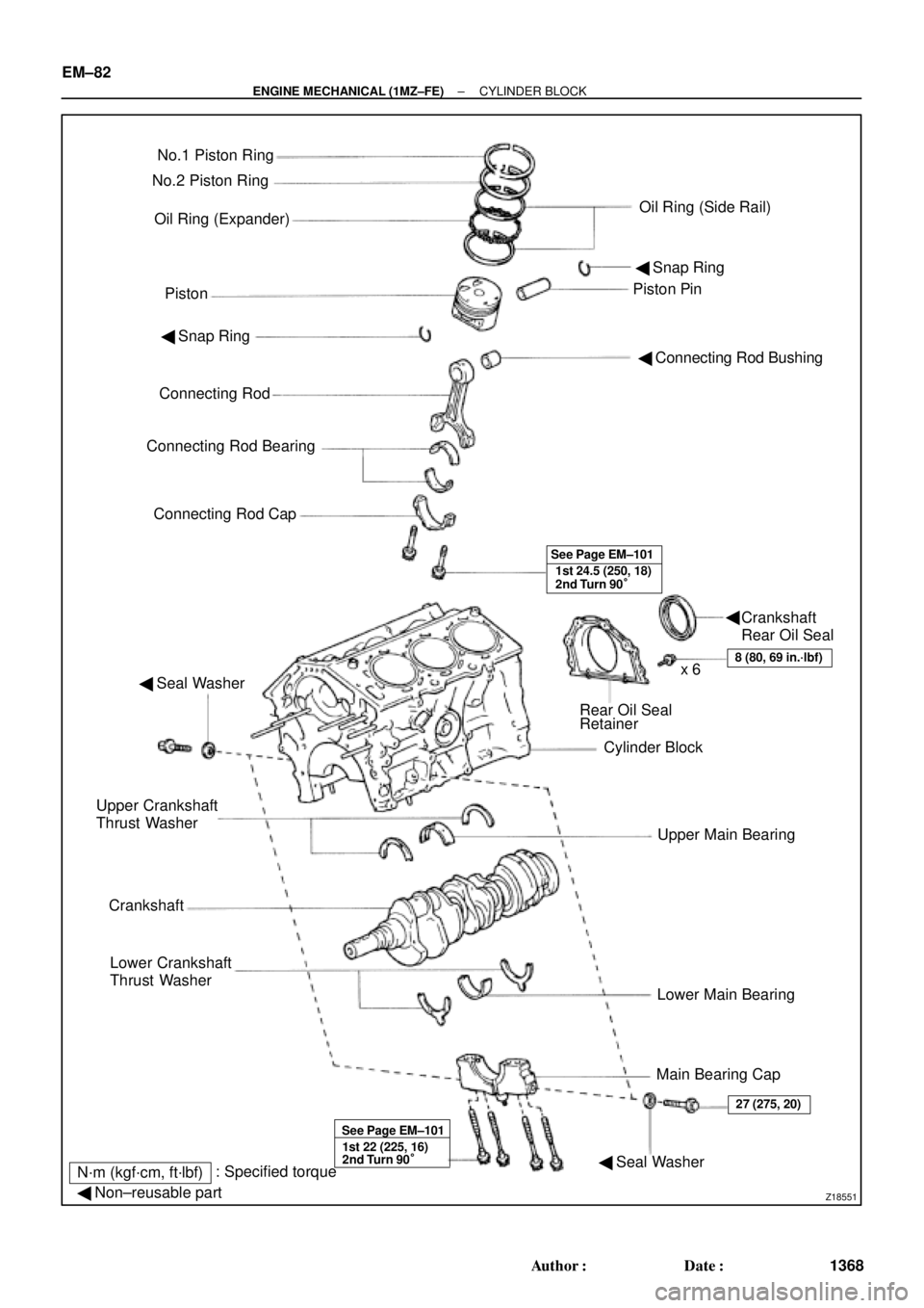
Z18551
No.1 Piston Ring
Oil Ring (Expander)
PistonPiston Pin No.2 Piston Ring
Oil Ring (Side Rail)
� Snap Ring
� Connecting Rod Bushing � Snap Ring
Connecting Rod
Connecting Rod Bearing
Connecting Rod Cap
1st 24.5 (250, 18)
2nd Turn 90° See Page EM±101
� Seal Washer
Rear Oil Seal
Retainer
Cylinder Block
Upper Main Bearing
Lower Main Bearing
Main Bearing Cap Upper Crankshaft
Thrust Washer
Crankshaft
Lower Crankshaft
Thrust Washer
8 (80, 69 in.´lbf)x 6
1st 22 (225, 16)
2nd Turn 90° See Page EM±101
� Seal Washer
27 (275, 20)
N´m (kgf´cm, ft´lbf): Specified torque
� Non±reusable part
Crankshaft
Rear Oil Seal � EM±82
± ENGINE MECHANICAL (1MZ±FE)CYLINDER BLOCK
1368 Author�: Date�:
Page 3589 of 4770
EM051±04
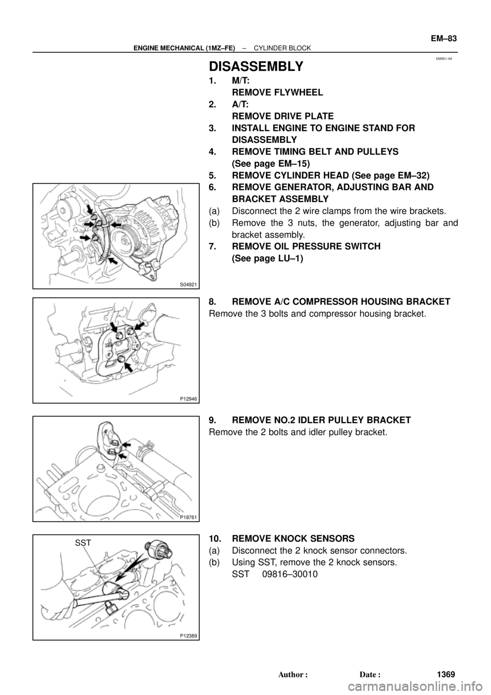
S04921
P12946
P18761
P12389
SST
± ENGINE MECHANICAL (1MZ±FE)CYLINDER BLOCK
EM±83
1369 Author�: Date�:
DISASSEMBLY
1. M/T:
REMOVE FLYWHEEL
2. A/T:
REMOVE DRIVE PLATE
3. INSTALL ENGINE TO ENGINE STAND FOR
DISASSEMBLY
4. REMOVE TIMING BELT AND PULLEYS
(See page EM±15)
5. REMOVE CYLINDER HEAD (See page EM±32)
6. REMOVE GENERATOR, ADJUSTING BAR AND
BRACKET ASSEMBLY
(a) Disconnect the 2 wire clamps from the wire brackets.
(b) Remove the 3 nuts, the generator, adjusting bar and
bracket assembly.
7. REMOVE OIL PRESSURE SWITCH
(See page LU±1)
8. REMOVE A/C COMPRESSOR HOUSING BRACKET
Remove the 3 bolts and compressor housing bracket.
9. REMOVE NO.2 IDLER PULLEY BRACKET
Remove the 2 bolts and idler pulley bracket.
10. REMOVE KNOCK SENSORS
(a) Disconnect the 2 knock sensor connectors.
(b) Using SST, remove the 2 knock sensors.
SST 09816±30010
Page 3590 of 4770
CYLINDER BLOCK
1370 Author�: Date�:
11. REMOVE WATER I")
P18762
P18763
WaterSeal
Plate
Oil Filter
Union
12 mm
Hexagon
Wrench
Coolant
Drain
Union
P12410
P12508
P12695
EM±84
± ENGINE MECHANICAL (1MZ±FE)CYLINDER BLOCK
1370 Author�: Date�:
11. REMOVE WATER INLET HOUSING
(a) Remove the engine wire band.
(b) Disconnect the engine wire clamp from the bracket.
(c) Remove the 8 bolts, 2 nuts and water inlet housing.
12. REMOVE WATER PUMP (See page CO±6)
13. REMOVE NO.2 OIL PAN (See page LU±9)
14. REMOVE OIL STRAINER (See page LU±9)
15. REMOVE NO.1 OIL PAN (See page LU±9)
16. REMOVE OIL PUMP (See page LU±9)
17. REMOVE OIL FILTER (See page LU±9)
18. REMOVE OIL FILTER UNION
Using a 12 mm hexagon wrench, remove the oil filter union.
19. REMOVE WATER SEAL PLATE
Remove the 2 nuts and seal plate.
20. REMOVE ENGINE COOLANT DRAIN UNION
21. REMOVE EGR COOLER
Remove the 3 bolts, 2 nuts, EGR cooler and gasket.
22. REMOVE REAR OIL SEAL RETAINER
(a) Remove the 6 bolts.
(b) Using a screwdriver, remove the oil seal retainer by prying
the portions between the oil seal retainer and main bear-
ing cap.
23. CHECK CONNECTING ROD THRUST CLEARANCE
Using a dial indicator, measure the thrust clearance while mov-
ing the connecting rod back and forth.
Standard thrust clearance:
0.15 ± 0.30 mm (0.0059 ± 0.0118 in.)
Maximum thrust clearance: 0.35 mm (0.0138 in.)
If the thrust clearance is greater than maximum, replace the
connecting rod assembly(s). If necessary, replace the crank-
shaft.