Page 3591 of 4770
P13329
P12707
P12696
P12728
Plastigage
± ENGINE MECHANICAL (1MZ±FE)CYLINDER BLOCK
EM±85
1371 Author�: Date�:
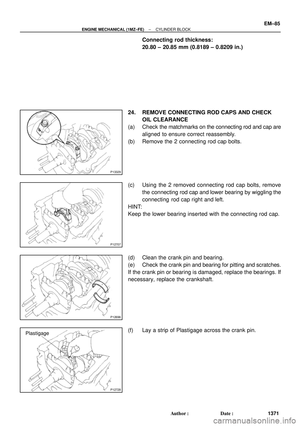
Connecting rod thickness:
20.80 ± 20.85 mm (0.8189 ± 0.8209 in.)
24. REMOVE CONNECTING ROD CAPS AND CHECK
OIL CLEARANCE
(a) Check the matchmarks on the connecting rod and cap are
aligned to ensure correct reassembly.
(b) Remove the 2 connecting rod cap bolts.
(c) Using the 2 removed connecting rod cap bolts, remove
the connecting rod cap and lower bearing by wiggling the
connecting rod cap right and left.
HINT:
Keep the lower bearing inserted with the connecting rod cap.
(d) Clean the crank pin and bearing.
(e) Check the crank pin and bearing for pitting and scratches.
If the crank pin or bearing is damaged, replace the bearings. If
necessary, replace the crankshaft.
(f) Lay a strip of Plastigage across the crank pin.
Page 3592 of 4770
CYLINDER BLOCK
1372 Author�: Date�:
(g) Install the connecting rod cap with the 2 bolts.
(See page EM±101)
Tor")
P12697
P12698
P14127
Number Mark
Number
Mark
P12500
EM±86
± ENGINE MECHANICAL (1MZ±FE)CYLINDER BLOCK
1372 Author�: Date�:
(g) Install the connecting rod cap with the 2 bolts.
(See page EM±101)
Torque:
1st: 24.5 N´m (250 kgf´cm, 18 ft´lbf)
2nd: Turn extra 90°
NOTICE:
Do not turn the crankshaft.
(h) Remove the 2 bolts, connecting rod cap and lower bear-
ing. (See steps (b) and (c))
(i) Measure the Plastigage at its widest point.
Standard oil clearance:
0.038 ± 0.064 mm (0.0015 ± 0.0025 in.)
Maximum oil clearance: 0.08 mm (0.0031 in.)
If the oil clearance is greater than maximum, replace the bear-
ings. If necessary, grind or replace the crankshaft.
HINT:
If replacing a bearing, replace it with one having the same num-
ber as marked on the connecting rod. There are 4 sizes of stan-
dard bearings, marked º1º, º2º, º3º and º4º accordingly.
Reference:
Standard bearing center wall thickness:
Markmm (in.)
º1º1.484 ± 1.487 (0.0584 ± 0.0585)
º2º1.487 ± 1.490 (0.0585 ± 0.0587)
º3º1.490 ± 1.493 (0.0587 ± 0.0588)
º4º1.493 ± 1.496 (0.0588 ± 0.0589)
(j) Completely remove the Plastigage.
25. REMOVE PISTON AND CONNECTING ROD
ASSEMBLIES
(a) Using a ridge reamer, remove all the carbon from the top
of the cylinder.
(b) Push the piston, connecting rod assembly and upper
bearing through the top of the cylinder block.
HINT:
�Keep the bearings, connecting rod and cap together.
�Arrange the piston and connecting rod assemblies in the
correct order.
Page 3593 of 4770
CYLINDER BLOCK
EM±87
1373 Author�: Date�:
26. CHECK CRANKSHAFT THRUST CLEARANCE
Using")
P12799
P12585
P12752
1011 12
1416
15
1 23 4
5
6
7 8
913
P12603
S06200
Joint Surface
± ENGINE MECHANICAL (1MZ±FE)CYLINDER BLOCK
EM±87
1373 Author�: Date�:
26. CHECK CRANKSHAFT THRUST CLEARANCE
Using a dial indicator, measure the thrust clearance while prying
the crankshaft back and forth with a screwdriver.
Standard thrust clearance:
0.04 ± 0.24 mm (0.0016 ± 0.0095 in.)
Maximum thrust clearance: 0.30 mm (0.0118 in.)
If the thrust clearance is greater than maximum, replace the
thrust washers as a set.
Thrust washer thickness:
1.930 ± 1.980 mm (0.0760 ± 0.0780 in.)
27. REMOVE MAIN BEARING CAPS AND CHECK OIL
CLEARANCE
(a) Uniformly loosen and remove the 8 main bearing cap
bolts and seal washers, in the several passes, in the se-
quence shown.
(b) Uniformly loosen and remove the 16 main bearing cap
bolts, in several passes, in the sequence shown.
(c) Using a screwdriver, pry out main bearing caps. Remove
the 4 main bearing caps, lower bearings and (No.2 main
bearing cap only) 2 lower thrust washers.
NOTICE:
Pull up the main bearing cap little by little to the right and
the left by turns and pay attention not to damage the joint
surface of the cylinder block and the main bearing cap.
HINT:
�Keep the lower bearing and main bearing cap together.
�Arrange the main bearing caps and lower thrust washers
in correct order.
Page 3594 of 4770
CYLINDER BLOCK
1374 Author�: Date�:
(d) Lift out the crankshaft.
HINT:
Keep the upper bearings together with the cylinder bl")
P12495
P12980
Plastigage
P12954
P12993
EM±88
± ENGINE MECHANICAL (1MZ±FE)CYLINDER BLOCK
1374 Author�: Date�:
(d) Lift out the crankshaft.
HINT:
Keep the upper bearings together with the cylinder block.
(e) Clean each main journal and bearing.
(f) Check each main journal and bearing for pitting and
scratches.
If the journal or bearing is damaged, replace the bearings. If
necessary, replace the crankshaft.
(g) Place the crankshaft on the cylinder block.
(h) Lay a strip of Plastigage across each journal.
(i) Install the 4 main bearing caps. (See page EM±101)
Torque:
12 pointed head bolts:
1st: 22 N´m (225 kgf´cm, 16 ft´lbf)
2nd: Turn extra 90°
Hexagon head bolts:
27 N´m (275 kgf´cm, 20 ft´lbf)
NOTICE:
Do not turn the crankshaft.
(j) Remove the main bearing caps. (See steps (a) to (c) )
(k) Measure the Plastigage at its widest point.
Standard oil clearance:
No.1 and No.4 journals0.014 ± 0.036 mm (0.0006 ± 0.0014 in.)
No.2 and No.3 journals0.026 ± 0.048 mm (0.0010 ± 0.0019 in.)
Maximum clearance:
No.1 and No.4 journals0.05 mm (0.0020 in.)
No.2 and No.3 journals0.06 mm (0.0024 in.)
If the oil clearance is greater than maximum, replace the bear-
ings. If necessary, replace the crankshaft.
Page 3598 of 4770
P12404
P12405
P12403
P12416
60°C
P12415
EM±92
± ENGINE MECHANICAL (1MZ±FE)CYLINDER BLOCK
1378 Author�: Date�:
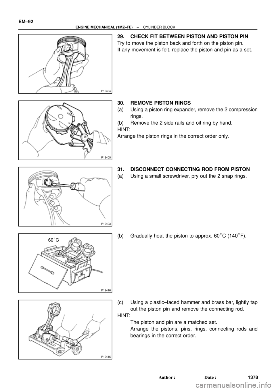
29. CHECK FIT BETWEEN PISTON AND PISTON PIN
Try to move the piston back and forth on the piston pin.
If any movement is felt, replace the piston and pin as a set.
30. REMOVE PISTON RINGS
(a) Using a piston ring expander, remove the 2 compression
rings.
(b) Remove the 2 side rails and oil ring by hand.
HINT:
Arrange the piston rings in the correct order only.
31. DISCONNECT CONNECTING ROD FROM PISTON
(a) Using a small screwdriver, pry out the 2 snap rings.
(b) Gradually heat the piston to approx. 60°C (140°F).
(c) Using a plastic±faced hammer and brass bar, lightly tap
out the piston pin and remove the connecting rod.
HINT:
�The piston and pin are a matched set.
�Arrange the pistons, pins, rings, connecting rods and
bearings in the correct order.
Page 3601 of 4770
CYLINDER BLOCK
EM±95
1381 Author�: Date�:
(b) Using a groove cleaning tool or broken ring, clean the pis-
ton")
P12491
P12505
S06041
AISIN Made
RH Piston
LH Piston23.2 mm
± ENGINE MECHANICAL (1MZ±FE)CYLINDER BLOCK
EM±95
1381 Author�: Date�:
(b) Using a groove cleaning tool or broken ring, clean the pis-
ton ring grooves.
(c) Using solvent and a brush, thoroughly clean the piston.
NOTICE:
Do not use a wire brush.
9. INSPECT PISTON OIL CLEARANCE
(a) AISIN made:
(1) Using a micrometer, measure the piston diameter at
right angles to the piston pin center line, 23.2 mm
(0.913 in.) from the piston head.
Piston diameter:
87.406 ± 87.416 mm (3.4412 ± 3.4416 in.)
(2) Measure the cylinder bore diameter in the thrust
directions. (See page EM±93)
(3) Subtract the piston diameter measurement from the
cylinder bore diameter measurement.
Standard oil clearance:
0.084 ± 0.106 mm (0.0033 ± 0.0042 in.)
Maximum oil clearance: 0.13 mm (0.0051 in.)
If the oil clearance is greater than maximum, replace all the 6
pistons. If necessary, replace the cylinder block.
HINT:
The shape of the piston varies for the RH and LH banks. The
RH piston is marked with ºRº, the LH piston with ºLº.
Page 3602 of 4770
CYLINDER BLOCK
1382 Author�: Date�:
(b) MAHLE made:
(1) Using a micrometer, measure the p")
S06042
MAHLE Made
RH Piston
41.2 mm
LH Piston
P12504
P12583
105 mm
EM7639
EM±96
± ENGINE MECHANICAL (1MZ±FE)CYLINDER BLOCK
1382 Author�: Date�:
(b) MAHLE made:
(1) Using a micrometer, measure the piston diameter at
right angles to the piston pin center line, 41.2 mm
(1.622 in.) from the piston head.
Piston diameter:
87.453 ± 87.467 mm (3.4430 ± 3.4436 in.)
(2) Measure the cylinder bore diameter in the thrust
directions. (See inspection in cylinder block)
(3) Subtract the piston diameter measurement from the
cylinder bore diameter measurement.
Standard oil clearance:
0.033 ± 0.059 mm (0.0013 ± 0.0023 in.)
Maximum oil clearance: 0.08 mm (0.0031 in.)
If the oil clearance is greater than maximum, replace all the 6
pistons. If necessary, replace the cylinder block.
HINT:
The shape of the piston varies for the RH and LH banks. The
RH piston is marked with ºRº, the LH piston with ºLº.
10. INSPECT PISTON RING GROOVE CLEARANCE
Using a feeler gauge, measure the clearance between new pis-
ton right and the wall of the ring groove.
Ring groove clearance:
No.10.020 ± 0.070 mm (0.0008 ± 0.0028 in.)
No.20.020 ± 0.060 mm (0.0008 ± 0.0024 in.)
If the clearance is not as specified, replace the piston.
11. INSPECT PISTON RING END GAP
(a) Insert the piston ring into the cylinder bore.
(b) Using a piston, push the piston ring a little beyond the bot-
tom of the ring travel, 105 mm (4.13 in.) from the top of the
cylinder block.
(c) Using a feeler gauge, measure the end gap.
Standard end gap:
No.10.25 ± 0.35 mm (0.0098 ± 0.0138 in.)
No.20.35 ± 0.45 mm (0.0138 ± 0.0177 in.)
Oil (Side rail)0.15 ± 0.40 mm (0.0059 ± 0.0157 in.)
Maximum end gap:
No.10.95 mm (0.0374 in.)
No.21.05 mm (0.0413 in.)
Oil (Side rail)1.00 mm (0.0394 in.)
Page 3603 of 4770
CYLINDER BLOCK
EM±97
1383 Author�: Date�:
If the end gap is greater than maximum, replace the piston ring.
If the end gap is greater than max")
P12506
Z04012
Z04011
EM6525
± ENGINE MECHANICAL (1MZ±FE)CYLINDER BLOCK
EM±97
1383 Author�: Date�:
If the end gap is greater than maximum, replace the piston ring.
If the end gap is greater than maximum, even with a new piston
ring, replace the cylinder block.
12. INSPECT PISTON PIN FIT
At 60°C (140°F), you should be able to push the piston pin into
the piston pin hole with your thumb.
13. INSPECT CONNECTING ROD ALIGNMENT
Using a rod aligner and feeler gauge, check the connecting rod
alignment.
�Check for out±of±alignment.
Maximum out±of±alignment:
0.05 mm (0.0020 in.) per 100 mm (3.94 in.)
If bend is greater than maximum, replace the connecting rod as-
sembly.
�Check for twist
Maximum twist:
0.15 mm (0.0059 in.) per 100 mm (3.94 in.)
If twist is greater than maximum, replace the connecting rod as-
sembly.
14. INSPECT PISTON PIN OIL CLEARANCE
(a) Using a caliper gauge, measure the inside diameter of the
connecting rod bushing.
Bushing inside diameter:
22.005 ± 22.014 mm (0.8663 ± 0.8667 in.)