Page 3545 of 4770
CYLINDER HEAD
EM±39
1325 Author�: Date�:
(2) Secur")
P12873Main Gear
Sub±GearService Bolt Intake
P12958
Intake
7
85
6
3
41
2
9
10
P12886
7
85 6
3 41 2
9 10 Exhaust
P12596
± ENGINE MECHANICAL (1MZ±FE)CYLINDER HEAD
EM±39
1325 Author�: Date�:
(2) Secure the exhaust camshaft sub±gear to the main
gear with a service bolt.
Recommended service bolt:
Thread diameter6 mm
Thread pitch1.0 mm
Bolt length16 ± 20 mm (0.63 ± 0.79 in.)
HINT:
When removing the camshaft, make sure that the torsional
spring force of the sub±gear has been eliminated by the above
operation.
(b) Uniformly loosen and remove the 10 bearing cap bolts, in
several passes, in the sequence shown.
(c) Remove the 5 bearing caps and intake camshaft.
(d) Remove the exhaust camshaft.
(1) Uniformly loosen and remove the 10 bearing cap
bolts, in several passes, in the sequence shown.
(2) Remove the 5 bearing caps, oil seal and exhaust
camshaft.
HINT:
�Arrange the camshafts in the correct order.
�Arrange the bearing caps in the correct order.
33. DISASSEMBLE EXHAUST CAMSHAFTS
(a) Mount the hexagonal wrench head portion of the cam-
shaft in a vise.
NOTICE:
Be careful not to damage the camshaft.
Page 3548 of 4770
EM04T±03
P12683
P12476
SST
P12686
P12720
Magnetic Finger EM±42
± ENGINE MECHANICAL (1MZ±FE)CYLINDER HEAD
1328 Author�: Date�:
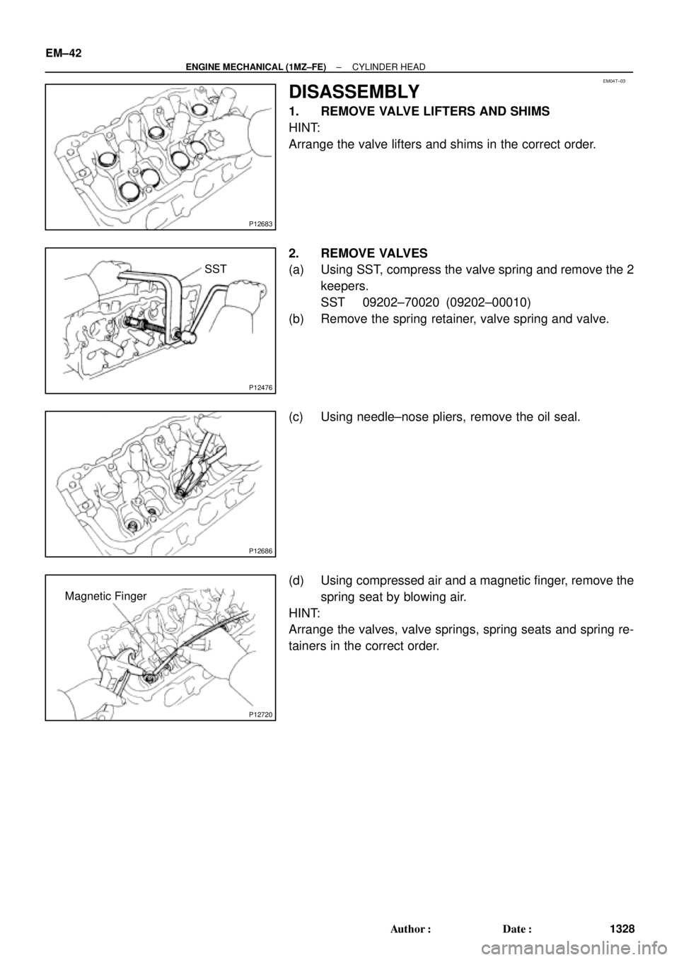
DISASSEMBLY
1. REMOVE VALVE LIFTERS AND SHIMS
HINT:
Arrange the valve lifters and shims in the correct order.
2. REMOVE VALVES
(a) Using SST, compress the valve spring and remove the 2
keepers.
SST 09202±70020 (09202±00010)
(b) Remove the spring retainer, valve spring and valve.
(c) Using needle±nose pliers, remove the oil seal.
(d) Using compressed air and a magnetic finger, remove the
spring seat by blowing air.
HINT:
Arrange the valves, valve springs, spring seats and spring re-
tainers in the correct order.
Page 3549 of 4770
CYLINDER HEAD
EM±43
1329 Author�: Date�:
INSPECTION
1. CLEAN TOP SURFACES OF PISTONS AND
CYLINDER BLOCK
(a) Turn the cranksh")
EM0YP±01
P12689
P12492
P12700
P12701
P12703
± ENGINE MECHANICAL (1MZ±FE)CYLINDER HEAD
EM±43
1329 Author�: Date�:
INSPECTION
1. CLEAN TOP SURFACES OF PISTONS AND
CYLINDER BLOCK
(a) Turn the crankshaft, and bring each piston to top dead
center (TDC). Using a gasket scraper, remove all the car-
bon from the piston top surface.
(b) Using a gasket scraper, remove all the gasket material
from the cylinder block surface.
(c) Using compressed air, blow carbon and oil from the bolt
holes.
CAUTION:
Protect your eyes when using high pressure compressed
air.
2. REMOVE GASKET MATERIAL
Using a gasket scraper, remove all the gasket material from the
cylinder block contact surface.
NOTICE:
Be careful not to scratch the cylinder block contact sur-
face.
3. CLEAN COMBUSTION CHAMBERS
Using a wire brush, remove all the carbon from the combustion
chambers.
NOTICE:
Be careful not to scratch the cylinder block contact sur-
face.
4. CLEAN CYLINDER HEADS
Using a soft brush and solvent, thoroughly clean the cylinder
head.
Page 3551 of 4770
CYLINDER HEAD
EM±45
1331 Author�: Date�:
9. INSPECT VALVE STEMS AND GUIDE BUSHINGS
(a) Using a caliper gauge, measure")
P12754
Z00052
Z00054
44.5°
EM0181
Margin Thickness
± ENGINE MECHANICAL (1MZ±FE)CYLINDER HEAD
EM±45
1331 Author�: Date�:
9. INSPECT VALVE STEMS AND GUIDE BUSHINGS
(a) Using a caliper gauge, measure the inside diameter of the
guide bushing.
Bushing inside diameter:
5.510 ± 5.530 mm (0.2169 ± 0.2177 in.)
(b) Using a micrometer, measure the diameter of the valve
stem.
Valve stem diameter:
Intake5.470 ± 5.485 mm (0.2154 ± 0.2159 in.)
Exhaust5.465 ± 5.480 mm (0.2152 ± 0.2157 in.)
(c) Subtract the valve stem diameter measurement from the
guide bushing guide bushing inside diameter measure-
ment.
Standard oil clearance:
Intake0.025 ± 0.060 mm (0.0010 ± 0.0024 in.)
Exhaust0.030 ± 0.065 mm (0.0012 ± 0.0026 in.)
Maximum oil clearance:
Intake0.08 mm (0.0031 in.)
Exhaust0.10 mm (0.0039 in.)
If the clearance is greater than maximum, replace the valve and
guide bushing.
10. INSPECT AND GRIND VALVES
(a) Grind the valve enough to remove pits and carbon.
(b) Check that the valve is ground to the correct valve face
angle.
Valve face angle: 44.5°
(c) Check the valve head margin thickness.
Standard margin thickness: 1.0 mm (0.039 in.)
Minimum margin thickness: 0.5 mm (0.020 in.)
If the margin thickness is less than minimum, replace the valve.
Page 3554 of 4770
CYLINDER HEAD
1334 Author�: Date�:
13. INSPECT CAMSHAFT FOR RUNOUT
(a) Place the camshaft on V±blocks.
(b) Using a dial indicator, mea")
EM1628
EM2011
EM2538
A05236
EM±48
± ENGINE MECHANICAL (1MZ±FE)CYLINDER HEAD
1334 Author�: Date�:
13. INSPECT CAMSHAFT FOR RUNOUT
(a) Place the camshaft on V±blocks.
(b) Using a dial indicator, measure the circle runout at the
center journal.
Maximum circle runout: 0.06 mm (0.0024 in.)
If the circle runout is greater than maximum, replace the cam-
shaft.
14. INSPECT CAM LOBES
Using a micrometer, measure the cam lobe height.
Standard cam lobe height:
Intake42.11 ± 42.21 mm (1.6579 ± 1.6618 in.)
Exhaust41.96 ± 42.06 mm (1.6520 ± 1.6559 in.)
Minimum cam lobe height:
Intake41.96 mm (1.6520 in.)
Exhaust41.81 mm (1.6461 in.)
If the cam lobe height is less than minimum, replace the cam-
shaft.
15. INSPECT CAMSHAFT JOURNALS
Using a micrometer, measure the journal diameter.
Journal diameter:
Intake26.949 ± 26.965 mm (1.0610 ± 1.0616 in.)
Exhaust26.959 ± 26.975 mm (1.0613 ± 1.0620 in.)
If the journal diameter is not as specified, check the oil clear-
ance.
16. INSPECT CAMSHAFT BEARINGS
Check that bearings for flaking and scoring.
If the bearings are damaged, replace the bearing caps and cyl-
inder head as a set.
Page 3555 of 4770
CYLINDER HEAD
EM±49
1335 Author�: Date�:
17. INSPECT CAMSHAFT JOURNAL OIL CLEARANCE
(a) Clean the bearing caps and camshaft journa")
P13009
Plastigage
P12892
P13004
P12891
± ENGINE MECHANICAL (1MZ±FE)CYLINDER HEAD
EM±49
1335 Author�: Date�:
17. INSPECT CAMSHAFT JOURNAL OIL CLEARANCE
(a) Clean the bearing caps and camshaft journals.
(b) Place the camshafts on the cylinder head.
(c) Lay a strip of Plastigage across each of the camshaft jour-
nal.
(d) Install the bearing caps. (See page EM±57)
Torque: 16 N´m (160 kgf´cm, 12 ft´lbf)
NOTICE:
Do not turn the camshaft.
(e) Remove the bearing caps.
(f) Measure the Plastigage at its widest point.
Standard oil clearance:
Intake0.035 ± 0.072 mm (0.0014 ± 0.0028 in.)
Exhaust0.025 ± 0.062 mm (0.0010 ± 0.0024 in.)
Maximum oil clearance:
Intake0.10 mm (0.0039 in.)
Exhaust0.09 mm (0.0035 in.)
If the oil clearance is greater than maximum, replace the cam-
shaft. If necessary, replace the bearing caps and cylinder head
as a set.
(g) Completely remove the Plastigage.
(h) Remove the camshafts.
18. INSPECT CAMSHAFT THRUST CLEARANCE
(a) Install the camshafts. (See page EM±57)
(b) Using a dial indicator, measure the thrust clearance while
moving the camshaft back and forth.
Standard thrust clearance:
0.040 ± 0.090 mm (0.0016 ± 0.0035 in.)
Maximum thrust clearance: 0.12 mm (0.0047 in.)
If the thrust clearance is greater than maximum, replace the
camshaft. If necessary, replace the bearing caps and cylinder
head as a set.
Page 3556 of 4770
CYLINDER HEAD
1336 Author�: Date�:
(c) Remove the camshafts.
19. INSPECT CAMSHAFT GEAR BACKLASH
(a) Install the camshafts")
P12960
EM3322
Free Distance
P12685
EM6368
EM±50
± ENGINE MECHANICAL (1MZ±FE)CYLINDER HEAD
1336 Author�: Date�:
(c) Remove the camshafts.
19. INSPECT CAMSHAFT GEAR BACKLASH
(a) Install the camshafts without installing the exhaust cam
sub±gear. (See page EM±57)
(b) Using a dial indicator, measure the backlash.
Standard backlash:
0.020 ± 0.200 mm (0.0008 ± 0.0079 in.)
Maximum backlash: 0.30 mm (0.0188 in.)
If the backlash is greater then maximum, replace the cam-
shafts.
(c) Remove the camshafts.
20. INSPECT CAMSHAFT GEAR SPRING
Using vernier calipers, measure the free distance between the
spring ends.
Free distance: 18.2 ± 18.8 mm (0.712 ± 0.740 in.)
If the free distance is not as specified, replace the gear spring.
21. INSPECT VALVE LIFTERS AND LIFTER BORES
(a) Using a caliper gauge, measure the lifter bore diameter
of the cylinder head.
Lifter bore diameter:
31.000 ± 31.018 mm (1.2205 ± 1.2212 in.)
(b) Using a micrometer, measure the lifter diameter.
Lifter diameter:
30.966 ± 30.976 mm (1.2191 ± 1.2195 in.)
(c) Subtract the lifter diameter measurement from the lifter
bore diameter measurement.
Standard oil clearance:
0.024 ± 0.050 mm (0.0009 ± 0.0020 in.)
Maximum oil clearance: 0.07 mm (0.0028 in.)
If the oil clearance is greater than maximum, replace the lifter.
If necessary, replace the cylinder head.
Page 3561 of 4770
Adhesive
P12572
Protrusion
P12869
Flush
P12719
SST
± ENGINE MECHANICAL (1MZ±FE)CYLINDER HEAD
EM±55
1341 Author�: Date�:
REASSEMBLY
HINT:
�Thoroughly c")
EM04V±04
P1151110 ± 15 mm (0.39 ± 0.59 in.)Adhesive
P12572
Protrusion
P12869
Flush
P12719
SST
± ENGINE MECHANICAL (1MZ±FE)CYLINDER HEAD
EM±55
1341 Author�: Date�:
REASSEMBLY
HINT:
�Thoroughly clean all parts to be assembled.
�Before installing the parts, apply new engine oil to all slid-
ing and rotating surfaces.
�Replace all gaskets and oil seals with new ones.
1. INSTALL SPARK PLUG TUBES
HINT:
When using a new cylinder head, spark plug tubes must be
installed.
(a) Apply adhesive to the end of the spark plug tube.
Adhesive:
Part No. 08833±00070, THREE BOND 1324
or equivalent
(b) Using a press, press in a new spark plug tube until there
is 42.4 ± 43.4 mm (1.669 ± 1.709 in.) protruding from the
camshaft bearing cap installation surface of the cylinder
head.
NOTICE:
Avoid pressing a new spark plug tube in too far by measur-
ing the amount of the protrusion while pressing.
2. INSTALL PCV PIPES
HINT:
When using a new cylinder head, PCV pipe must be installed.
Using a wooden block and hammer, tap in a new PCV pipe until
its top side is flush with the cylinder head edge.
NOTICE:
Be careful not to damage the cylinder head edge.
3. INSTALL VALVES
(a) Using SST, push in a new oil seal.
SST 09201±41020