Page 1561 of 4770

AC0M4±02
N01143
W
N01150
± AIR CONDITIONINGCOMPRESSOR AND MAGNETIC CLUTCH
AC±39
2521 Author�: Date�:
COMPRESSOR AND MAGNETIC
CLUTCH
ON±VEHICLE INSPECTION
1. INSPECT COMPRESSOR FOR METALLIC SOUND
(a) Start engine.
(b) Check if there is a metallic sound from the compressor
when the A/C switch is on.
If metallic sound is heard, replace the compressor assembly.
2. INSPECT REFRIGERANT PRESSURE
See ºON±VEHICLE INSPECTIONº of AIR CONDITIONING
SYSTEM on page AC±3.
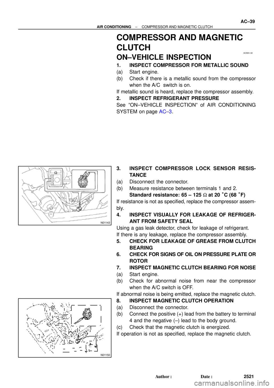
3. INSPECT COMPRESSOR LOCK SENSOR RESIS-
TANCE
(a) Disconnect the connector.
(b) Measure resistance between terminals 1 and 2.
Standard resistance: 65 ± 125 W at 20 °C (68 °F)
If resistance is not as specified, replace the compressor assem-
bly.
4. INSPECT VISUALLY FOR LEAKAGE OF REFRIGER-
ANT FROM SAFETY SEAL
Using a gas leak detector, check for leakage of refrigerant.
If there is any leakage, replace the compressor assembly.
5. CHECK FOR LEAKAGE OF GREASE FROM CLUTCH
BEARING
6. CHECK FOR SIGNS OF OIL ON PRESSURE PLATE OR
ROTOR
7. INSPECT MAGNETIC CLUTCH BEARING FOR NOISE
(a) Start engine.
(b) Check for abnormal noise from near the compressor
when the A/C switch is OFF.
If abnormal noise is being emitted, replace the magnetic clutch.
8. INSPECT MAGNETIC CLUTCH OPERATION
(a) Disconnect the connector.
(b) Connect the positive (+) lead from the battery to terminal
4 and the negative (±) lead to the body ground.
(c) Check that the magnetic clutch is energized.
If operation is not as specified, replace the magnetic clutch.
Page 1562 of 4770
AC0M5±02
I03331
5S±FE engine :
Drive BeltCompressor� O±Ring
Suction Hose
Discharge Hose
10 (100, 7)
10 (100, 7)
� O±Ring
25 (250, 18)
1MZ±FE engine :
� O±Ring
Drive Belt
Drive Belt Adjusting
Bar BracketGenerator
Discharge Hose
10 (100, 7)
10 (100, 7)
25 (250, 18)
Compressor
25 (250, 18)
25 (250, 18)
ShimSuction Hose � O±Ring
25 (250, 18)
56 (570, 41)
18 (185, 13)
13.2 (135, 9)
Rotor Pressure Plate
: Specified torque
N´m (kgf´cm, ft´lbf)Stator
Compressor
� Snap Ring
� Non±reusable part
Compressor
Bracket AC±40
± AIR CONDITIONINGCOMPRESSOR AND MAGNETIC CLUTCH
2522 Author�: Date�:
COMPONENTS
Page 1563 of 4770

AC0M6±02
N20277
P19978
± AIR CONDITIONINGCOMPRESSOR AND MAGNETIC CLUTCH
AC±41
2523 Author�: Date�:
REMOVAL
1. RUN ENGINE AT IDLE SPEED WITH A/C ON FOR
APPROX.10 MINUTES
2. STOP ENGINE
3. DISCONNECT NEGATIVE (±) TERMINAL CABLE
FROM BATTERY
4. DISCHARGE REFRIGERANT FROM REFRIGERATION
SYSTEM
5. REMOVE DRIVE BELT
(See page AC±17)
6. 1MZ±FE engine models:
REMOVE SUCTION HOSE
(a) Remove the suction hose clamping bolt.
(b) Disconnect the wire harness clamp.
(c) Loosen the nut and bolts and remove the suction hose.
NOTICE:
Cap the open fittings immediately to keep moisture or dirt
out of the system.
7. 1MZ±FE engine models:
DISCONNECT DISCHARGE HOSE
Remove the bolt and disconnect the hose.
NOTICE:
Cap the open fittings immediately to keep moisture or dirt
out of the system.
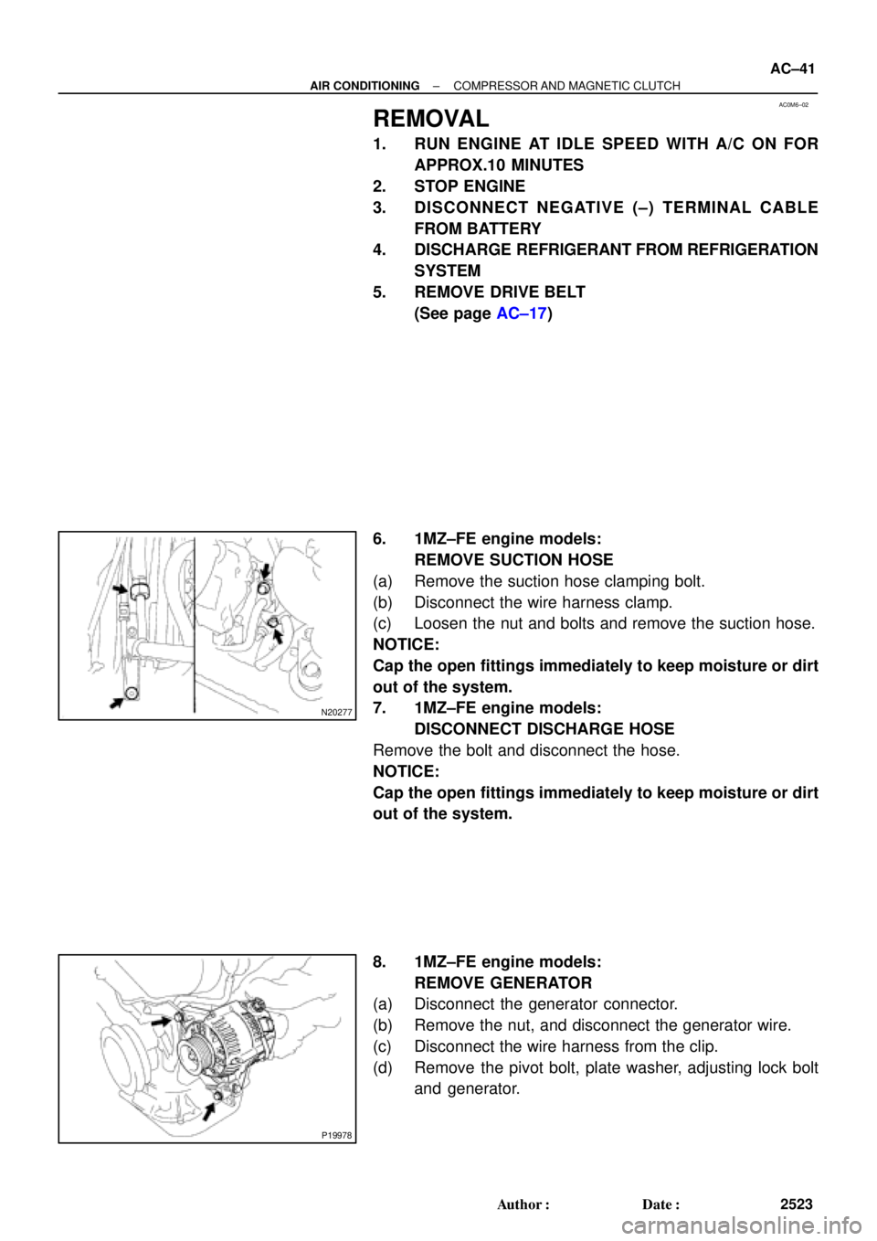
8. 1MZ±FE engine models:
REMOVE GENERATOR
(a) Disconnect the generator connector.
(b) Remove the nut, and disconnect the generator wire.
(c) Disconnect the wire harness from the clip.
(d) Remove the pivot bolt, plate washer, adjusting lock bolt
and generator.
Page 1565 of 4770
AC0M7±02
AC0943
SST
AC0944
SST
AC0945
SST
AC0946
Shim
Pressure
Plate
AC0947
SST
± AIR CONDITIONINGCOMPRESSOR AND MAGNETIC CLUTCH
AC±43
2525 Author�: Date�:
DISASSEMBLY
1. REMOVE PRESSURE PLATE
(a) Using SST and a socket wrench, remove the shaft bolt.
SST 07112±76060
Torque: 13.2 N´m (135 kgf´cm, 9 ft´lbf)
(b) Install SST on the pressure plate.
SST 07112±66040
(c) Using SST and socket wrench, remove the pressure
plate.
SST 07112±66040, 07112±76060
(d) Remove the shims from the pressure plate.
2. REMOVE ROTOR
(a) Using SST, remove the snap ring.
SST 07114±84020
Page 1568 of 4770
AC0M8±02
N04963
Dial Indicator AC±46
± AIR CONDITIONINGCOMPRESSOR AND MAGNETIC CLUTCH
2528 Author�: Date�:
REASSEMBLY
Reassembly is in the reverse order of disassembly
(See page AC±43).
AFTER REASSEMBLY, CHECK MAGNETIC CLUTCH
CLEARANCE
(a) Set the dial indicator to the pressure plate of the magnetic
clutch.
(b) Connect the magnetic clutch lead wire to the positive (+)
terminal of the battery.
(c) Check the clearance between the pressure plate and ro-
tor when connecting the negative (±) terminal to the bat-
tery.
Standard clearance:
0.5 ± 0.15 mm (0.020 ± 0.0059 in.)
If the clearance is not within the standard clearance, adjust the
clearance using shims to obtain the standard clearance.
Shim thickness:
0.1 mm (0.004 in.)
0.3 mm (0.012 in.)
0.5 mm (0.020 in.)
Page 1624 of 4770
INTRODUCTIONABBREVIATIONS USED IN THIS MANUAL ±
IN±9
ABBREVIATIONS USED IN THIS
MANUAL
AT FAutomatic Transaxle Fluid
B0Overdrive Brake
B1Second coast Brake
B2Second Brake
B3First and Reverse Brake
C0Overdrive Direct Clutch
C1Forward Clutch
C2Direct Clutch
DDisc
FFlange
F0O/D One±way Clutch
F1No.1 One±way Clutch
F2No.2 One±way Clutch
MPMultipurpose
O/DOverdirve
PPlate
SSMSpecial Service Materials
SSTSpecial Service Tools
IN01H±0R
Page 1635 of 4770
AUTOMATIC TRANSAXLEGENERAL DESCRIPTION ±
AX±2
General Specifications
Type of TransaxleA140E
Type of Engine5S±FE
Torque Converter Clutch Stall Torque Ratio2.0 : 1
Lock±up MechanismEquipped
Gear Ratio 1st Gear
2nd Gear
3rd Gear
O/D Gear
Reverse Gear2.810
1.549
1.000
0.706
2.296
Number of Discs and Plates O/D Direct Clutch (C0)
Forward Clutch (C
1)
Direct Clutch (C
2)
Second Brake (B
2)
First and Reverse Brake (B
3)
O/D Brake (B
0)
2/1
4/4
3/3
3/3
6/5
2/3
B1 Band Width mm (in.)25 mm (0.98 in.)
ATF TypeATF DEXRON ® @@@@@: [g 2]
Capacity liter (US qts, Imp. qts)
Transaxle
Differential
5.6 (5.9, 4.9)
1.6 (1.7, 1.4)
Page 1665 of 4770

AUTOMATIC TRANSAXLECOMPONENT PARTS ±
AX±32
COMPONENT PARTS
GENERAL NOTES
The instructions here are organized so that you work on only one component group at a time.
This will help avoid confusion from similar±looking parts of different subassemblies being on your work-
bench at the same time.
The component groups are inspected and repaired from the converter housing side.
As much as possible, complete the inspection, repair and assembly before proceeding to the next com-
ponent group. If a component group cannot be assembled because parts are being ordered, be sure
to keep all parts of that group in a separate container while proceeding with disassembly, inspection,
repair and assembly of other component groups.
Recommended fluid for the automatic transaxle:
DEXRON ® @@@@@: [g 2]
GENERAL CLEANING NOTES:
1. All disassembled parts should be washed clean and any fluid passages and holes blown through with
compressed air.
2. When using compressed air to dry parts, always aim away from yourself to prevent accidentally spray-
ing automatic transmission fluid or kerosene in your face.
3. The recommended automatic transaxle fluid or kerosene should be used for cleaning.
PARTS ARRANGEMENT:
1. After cleaning, the parts should be arranged in the correct order to allow efficient inspection, repairs,
and reassembly.
2. When disassembling a valve body, be sure to keep each valve together with the corresponding spring.
3. New brakes and clutches that are to be used for replacement must be soaked in transaxle fluid for at
least 15 minutes before assembly.
GENERAL ASSEMBLY:
1. All oil seal rings, clutch discs, clutch plates, rotating parts, and sliding surfaces should be coated with
transmission fluid prior to reassembly.
2. All gaskets and rubber O±rings should be replaced.
3. Make sure that the ends of a snap ring are not aligned with one of the cutouts and are installed in the
groove correctly.
4. If a worn bushing is to be replaced, the subassembly containing that bushing must be replaced.
5. Check thrust bearings and races for wear or damage. Replace if necessary.
6. Use petroleum jelly to keep parts in place.
AX0EY±02