Page 4018 of 4770

SS0BL±01
SS±56
± SERVICE SPECIFICATIONSAUTOMATIC TRANSAXLE (A541E)
219 Author�: Date�:
AUTOMATIC TRANSAXLE (A541E)
SERVICE DATA
Line pressure (wheel locked)Engine idling
D position
R position
at stall (Throttle valve fully opened)
D position
R position
401 ± 461 kPa (4.1 ± 4.7 kgf/cm2, 58 ± 66 psi)
804 ± 882 kPa (8.2 ± 9.0 kgf/cm2, 117 ± 128 psi)
1,138 ± 1,236 kPa (11.6 ± 12.6 kgf/cm
2, 165 ± 179 psi)
1,716 ± 1,854 kPa (17.5 ± 18.9 kgf/cm2, 249 ± 269 psi)
Engine stall revolution2,600 ± 150 rpm
Time lag N " D position
N " R positionLess than 1.2 seconds
Less than 1.5 seconds
Engine idle speed (A/C OFF)
N position
700 ± 50 rpm
Throttle cable adjustment (Throttle valve fully opened)Between boot and face and inner cable stopper
0 ± 1 mm (0 ± 0.04 in.)
Drive plate runoutMax.
Torque converter clutch runout Max.
Torque converter clutch installation distance0.3 mm (0.0118 in.)
0.20 mm (0.0079 in.)
More than 13.7 mm (0.539 in.)
Lock±up point (Throttle valve opening 5%)
3rd gear (O/D main switch OFF) Lock±up ON
Lock±up OFF
O/D gear Lock±up ON
Lock±up OFF
60 ± 65 km/h (37 ± 40 mph)
53 ± 58 km/h (33 ± 36 mph)
60 ± 64 km/h (37 ± 40 mph)
53 ± 58 km/h (33 ± 36 mph)
Shift schedule
D position
(Throttle valve fully opened) 1 "2
2 "3
3 "O/D
O/D "3
3 "2
2 "1
(Throttle valve fully closed) 3 "O/D
O/D "3
2 position
(Throttle valve fully opened) 1 "2
3 "2
2 "1
L position
(Throttle valve fully opened) 3 "2
2 "1
60 ± 66 km/h (37 ± 41 mph)
112 ± 121 km/h (70 ± 75 mph)
174 ± 183 km/h (108 ± 114 mph)
167 ± 176 km/h (104 ± 109 mph)
104 ± 112 km/h (65 ± 70 mph)
50 ± 55 km/h (31 ± 34 mph)
35 ± 40 km/h (22 ± 25 mph)
20 ± 25 km/h (12 ± 16 mph)
60 ± 66 km/h (37 ± 41 mph)
122 ± 130 km/h (76 ± 81 mph)
50 ± 55 km/h (31 ± 34 mph)
106 ± 115 km/h (66 ± 71 mph)
54 ± 59 km/h (34 ± 37 mph)
Page 4019 of 4770

SS0BM±01
± SERVICE SPECIFICATIONSAUTOMATIC TRANSAXLE (A541E)
SS±57
220 Author�: Date�:
TORQUE SPECIFICATION
Part tightenedN´mkgf´cmft´lbf
Front engine front mounting insulator x Front frame assemblyTMC:
TMMK:
Green color bolt
Silver color bolt80
66
44820
670
45059
48
32
Rear engine mounting insulator x Front frame assembly8082059
LH transaxle mounting insulator x Transaxle6465047
Engine mounting absorber x Front frame assembly4849035
Transaxle x Engine 17 mm bolt6667048
Transaxle x Engine 12 mm bolt4849035
Torque converter clutch x Drive plate4142030
Valve body x Transaxle case1111 08
Oil strainer x Valve body1111 08
Oil pan x Transaxle case7.88069 in.´lbf
Oil pan drain plug4950036
Park/Neutral position switch x Transaxle case (bolt)5.45548 in.´lbf
Park/Neutral position switch (nut)6.97061 in.´lbf
B3 apply pipe retainer1111 08
Connector clamp1111 08
Manual valve body x Transaxle case1111 08
Detent spring x Manual valve body1111 08
Oil pipe bracket101007
Steering gear housing x Front suspension member1811,850134
Stabilizer bar bracket1919514
Vehicle speed sensor x Transaxle case4.95043 in.´lbf
Direct clutch speed sensor x Transaxle case1111 08
Transfer lubrication apply pipe retainer1111 08
Exhaust manifold bracket x Transaxle case Except California
California20
34200
35014
25
Exhaust manifold plate Except California
California20
34200
35014
25
Front frame x Body 19 mm1811,850134
Front frame x Body 14 mm3233024
Front frame x Body Nut3637027
Exhaust front pipe x Exhaust center pipe5657041
Exhaust manifold x Exhaust front pipe6263046
Exhaust front pipe support stay x Exhaust front pipe support bracket3333024
Exhaust pipe support x Front frame3333024
Starter x Torque converter clutch housing3940029
Transaxle control shaft lever x Park/neutral position switch1515011
Throttle cable adjusting nut1515011
Drive plate x Crankshaft8385061
Shift control cable x Transaxle control shaft lever1515011
Throttle cable retaining plate set bolt5.45548 in.´lbf
Shift solenoid valve No.1, No.2, SL, SLN x Valve body6.66758 in.´lbf
Page 4260 of 4770

P13481
No Continuity Ohmmeter
B01162
Lock
Free
B01163
Ohmmeter
Terminal 50Terminal C
Continuity
B01164
Ohmmeter
Terminal 50Continuity
ST±10
± STARTING (5S±FE)STARTER
1717 Author�: Date�:
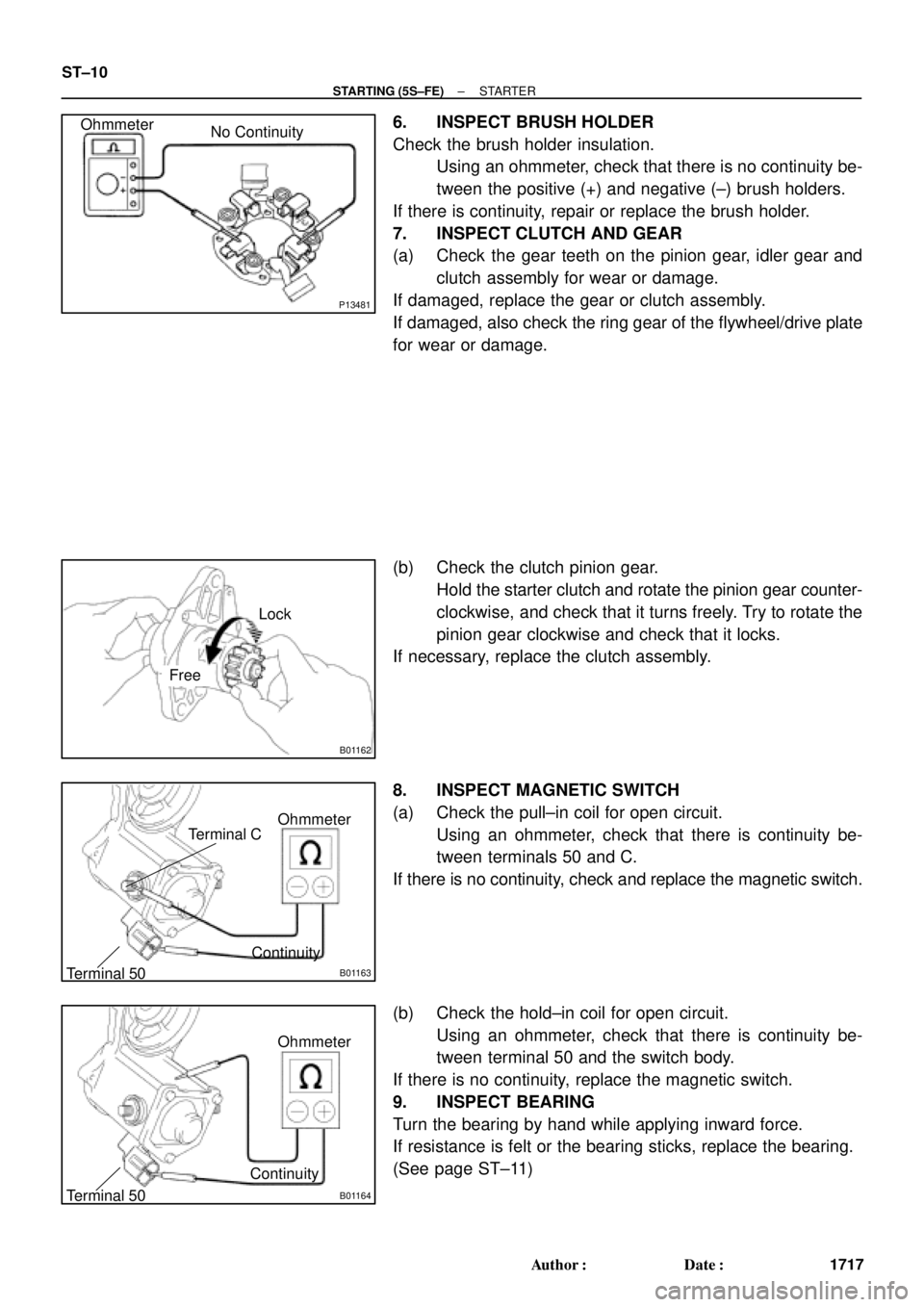
6. INSPECT BRUSH HOLDER
Check the brush holder insulation.
Using an ohmmeter, check that there is no continuity be-
tween the positive (+) and negative (±) brush holders.
If there is continuity, repair or replace the brush holder.
7. INSPECT CLUTCH AND GEAR
(a) Check the gear teeth on the pinion gear, idler gear and
clutch assembly for wear or damage.
If damaged, replace the gear or clutch assembly.
If damaged, also check the ring gear of the flywheel/drive plate
for wear or damage.
(b) Check the clutch pinion gear.
Hold the starter clutch and rotate the pinion gear counter-
clockwise, and check that it turns freely. Try to rotate the
pinion gear clockwise and check that it locks.
If necessary, replace the clutch assembly.
8. INSPECT MAGNETIC SWITCH
(a) Check the pull±in coil for open circuit.
Using an ohmmeter, check that there is continuity be-
tween terminals 50 and C.
If there is no continuity, check and replace the magnetic switch.
(b) Check the hold±in coil for open circuit.
Using an ohmmeter, check that there is continuity be-
tween terminal 50 and the switch body.
If there is no continuity, replace the magnetic switch.
9. INSPECT BEARING
Turn the bearing by hand while applying inward force.
If resistance is felt or the bearing sticks, replace the bearing.
(See page ST±11)
Page 4280 of 4770

P13481
No Continuity Ohmmeter
B01162
Lock
Free
B01163
Ohmmeter
Terminal 50Terminal C
Continuity
B01164
Ohmmeter
Terminal 50Continuity
ST±10
± STARTING (1MZ±FE)STARTER
1737 Author�: Date�:
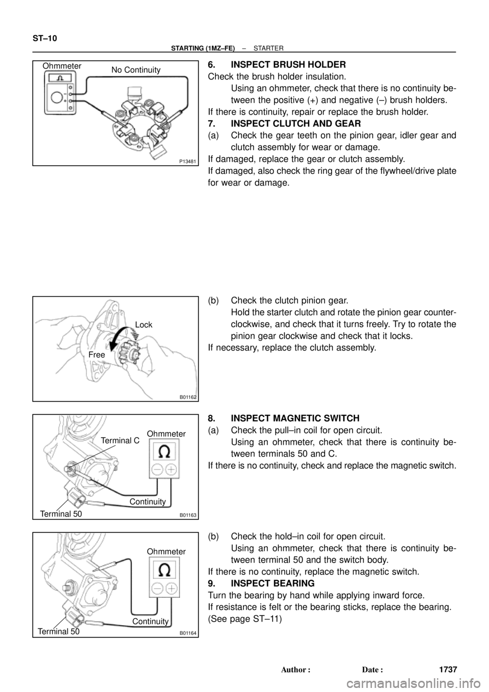
6. INSPECT BRUSH HOLDER
Check the brush holder insulation.
Using an ohmmeter, check that there is no continuity be-
tween the positive (+) and negative (±) brush holders.
If there is continuity, repair or replace the brush holder.
7. INSPECT CLUTCH AND GEAR
(a) Check the gear teeth on the pinion gear, idler gear and
clutch assembly for wear or damage.
If damaged, replace the gear or clutch assembly.
If damaged, also check the ring gear of the flywheel/drive plate
for wear or damage.
(b) Check the clutch pinion gear.
Hold the starter clutch and rotate the pinion gear counter-
clockwise, and check that it turns freely. Try to rotate the
pinion gear clockwise and check that it locks.
If necessary, replace the clutch assembly.
8. INSPECT MAGNETIC SWITCH
(a) Check the pull±in coil for open circuit.
Using an ohmmeter, check that there is continuity be-
tween terminals 50 and C.
If there is no continuity, check and replace the magnetic switch.
(b) Check the hold±in coil for open circuit.
Using an ohmmeter, check that there is continuity be-
tween terminal 50 and the switch body.
If there is no continuity, replace the magnetic switch.
9. INSPECT BEARING
Turn the bearing by hand while applying inward force.
If resistance is felt or the bearing sticks, replace the bearing.
(See page ST±11)