Page 2327 of 4770
CL034±01
± CLUTCHTROUBLESHOOTING
CL±1
1780 Author�: Date�:
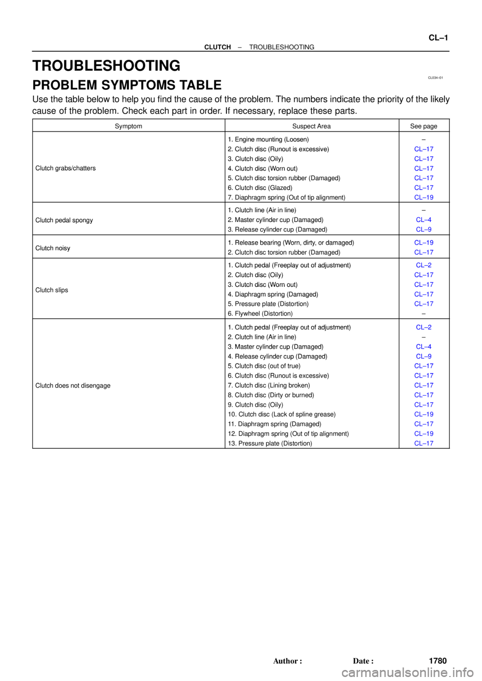
TROUBLESHOOTING
PROBLEM SYMPTOMS TABLE
Use the table below to help you find the cause of the problem. The numbers indicate the priority of the likely
cause of the problem. Check each part in order. If necessary, replace these parts.
SymptomSuspect AreaSee page
1. Engine mounting (Loosen)±1. Engine mounting (Loosen)
2. Clutch disc (Runout is excessive)
±
CL±17
2. Clutch disc (Runout is excessive)
3. Clutch disc (Oily)
CL±17
CL±17
Clutch grabs/chatters
3. Clutch disc (Oily)
4. Clutch disc (Worn out)
CL±17
CL±17Clutch grabs/chatters4. Clutch disc (Worn out)
5. Clutch disc torsion rubber (Damaged)
CL±17
CL±175. Clutch disc torsion rubber (Damaged)
6. Clutch disc (Glazed)
CL 17
CL±176. Clutch disc (Glazed)
7. Diaphragm spring (Out of tip alignment)
CL 17
CL±19
1. Clutch line (Air in line)±
Clutch pedal spongy
1. Clutch line (Air in line)
2. Master cylinder cup (Damaged)
±
CL±4
Clutch edal s ongy2. Master cylinder cu (Damaged)
3. Release cylinder cup (Damaged)
CL 4
CL±9
1 Release bearing (Worn dirty or damaged)CL 19Clutch noisy1. Release bearing (Worn, dirty, or damaged)
2Cl hdi i bb (D d)
CL±19
CL 17Clutch noisy2. Clutch disc torsion rubber (Damaged)CL±17
1. Clutch pedal (Freeplay out of adjustment)CL±21. Clutch edal (Free lay out of adjustment)
2. Clutch disc (Oily)
CL±2
CL±17
Cl t h li
2. Clutch disc (Oily)
3. Clutch disc (Worn out)
CL±17
CL±17Clutch slips3. Clutch disc (Worn out)
4. Diaphragm spring (Damaged)
CL 17
CL±174. Dia hragm s ring (Damaged)
5. Pressure plate (Distortion)
CL 17
CL±175. Pressure late (Distortion)
6. Flywheel (Distortion)
CL 17
±
1 Clutchpedal (Freeplay out of adjustment)CL±21. Clutch pedal (Freeplay out of adjustment)
2 Clutch line (Air in line)CL±2
2. Clutch line (Air in line)
3 Master cylinder cup(Damaged)
±
CL 43. Master cylinder cup (Damaged)
4 Release cylinder cup(Damaged)
CL±4
CL 94. Release cylinder cup (Damaged)
5 Clutch disc (out of true)
CL±9
CL 175. Clutch disc (out of true)
6 Cl tch disc (R no t is e cessi e)
CL±17
CL 17
Cl t h d t di
6. Clutch disc (Runout is excessive)
7 Cl t h di (Li i b k )
CL±17
CL 17Clutch does not disengage7. Clutch disc (Lining broken)
8 Cl t h di (Di t b d)
CL±17
CL 178. Clutch disc (Dirty or burned)
Cl h di (Oil )
CL±17
CL9. Clutch disc (Oily)CL±17
10. Clutch disc (Lack of spline grease)CL±19
11. Diaphragm spring (Damaged)CL±17gg(g)
12. Diaphragm spring (Out of tip alignment)CL±19gg( g)
13. Pressure plate (Distortion)CL±17
Page 3303 of 4770
I00281
Cruise Control ECU
C15
G±B
2 1 34W±B
3
STOP Fuse8 Stop Light Switch
4
R±Y
Stop Lights Cruise Control Actuator
� Actuator Magnetic Clutch
J7
J7AAJ/C
W±B
1J
1J
W±B
A
J/C
IG 8
7
J11Instrument
Panel J/BL
± DIAGNOSTICSCRUISE CONTROL SYSTEM
DI±883
111 8 Author�: Date�:
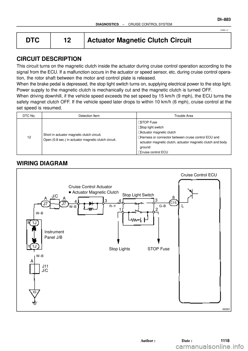
DTC 12 Actuator Magnetic Clutch Circuit
CIRCUIT DESCRIPTION
This circuit turns on the magnetic clutch inside the actuator during cruise control operation according to the
signal from the ECU. If a malfunction occurs in the actuator or speed sensor, etc. during cruise control opera-
tion, the rotor shaft between the motor and control plate is released.
When the brake pedal is depressed, the stop light switch turns on, supplying electrical power to the stop light.
Power supply to the magnetic clutch is mechanically cut and the magnetic clutch is turned OFF.
When driving downhill, if the vehicle speed exceeds the set speed by 15 km/h (9 mph), the ECU turns the
safety magnet clutch OFF. If the vehicle speed later drops to within 10 km/h (6 mph), cruise control at the
set speed is resumed.
DTC No.Detection ItemTrouble Area
12Short in actuator magnetic clutch circuit.
Open (0.8 sec.) in actuator magnetic clutch circuit.
�STOP Fuse
�Stop light switch
�Actuator magnetic clutch
�Harness or connector between cruise control ECU and
actuator magnetic clutch, actuator magnetic clutch and body
ground
�Cruise control ECU
WIRING DIAGRAM
DI08N±12
Page 3459 of 4770
S05316
M/T
Engine
No.2 Exhaust
Manifold Stay
(TMMK Made)
(TMC Made)
Exhaust Pipe Bracket
Oil Pan
Insulator
No.1 Exhaust
Manifold Stay
Back±Up Light Switch ConnectorNo.2 Rear End Plate Flywheel
LH Stiffener Plate
Clutch Disk
Clutch Cover
Engine Wire
VSS Connector
Wire Clamp
Ground Strap
Transaxle No.1 Rear End PlateIntake Manifold
Stay RH Stiffener Plate
N´m (kgf´cm, ft´lbf)
� Precoated partx 8
88 (900, 65)
19 (195, 14)
64(650, 47)
64(650, 47)
64(650, 47)64(650, 47)
�
: Specified torquex 6
± ENGINE MECHANICAL (5S±FE)ENGINE UNIT
EM±67
1239 Author�: Date�:
Page 3465 of 4770
S05526
TMMK
Made
TMC
Made
A02198
S05530
S05529
Turn
± ENGINE MECHANICAL (5S±FE)ENGINE UNIT
EM±73
1245 Author�: Date�:
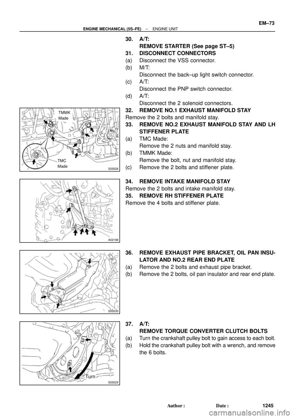
30. A/T:
REMOVE STARTER (See page ST±5)
31. DISCONNECT CONNECTORS
(a) Disconnect the VSS connector.
(b) M/T:
Disconnect the back±up light switch connector.
(c) A/T:
Disconnect the PNP switch connector.
(d) A/T:
Disconnect the 2 solenoid connectors.
32. REMOVE NO.1 EXHAUST MANIFOLD STAY
Remove the 2 bolts and manifold stay.
33. REMOVE NO.2 EXHAUST MANIFOLD STAY AND LH
STIFFENER PLATE
(a) TMC Made:
Remove the 2 nuts and manifold stay.
(b) TMMK Made:
Remove the bolt, nut and manifold stay.
(c) Remove the 2 bolts and stiffener plate.
34. REMOVE INTAKE MANIFOLD STAY
Remove the 2 bolts and intake manifold stay.
35. REMOVE RH STIFFENER PLATE
Remove the 4 bolts and stiffener plate.
36. REMOVE EXHAUST PIPE BRACKET, OIL PAN INSU-
LATOR AND NO.2 REAR END PLATE
(a) Remove the 2 bolts and exhaust pipe bracket.
(b) Remove the 2 bolts, oil pan insulator and rear end plate.
37. A/T:
REMOVE TORQUE CONVERTER CLUTCH BOLTS
(a) Turn the crankshaft pulley bolt to gain access to each bolt.
(b) Hold the crankshaft pulley bolt with a wrench, and remove
the 6 bolts.
Page 3466 of 4770
S05531
Wire
Bracket
Ground
Strap
S05314
M/T EM±74
± ENGINE MECHANICAL (5S±FE)ENGINE UNIT
1246 Author�: Date�:
38. REMOVE TRANSAXLE
(a) Remove the 4 bolts, ground strap and wire bracket.
(b) Remove the transaxle together with the torque converter
clutch (A/T) from the engine.
39. M/T:
REMOVE CLUTCH COVER AND DISC
40. M/T:
REMOVE FLYWHEEL
Remove the 8 bolts and flywheel.
41. A/T:
REMOVE DRIVE PLATE
Remove the 8 bolts, front spacer, drive plate and rear spacer.
42. REMOVE NO.1 REAR END PLATE
Remove the bolt and end plate.
Page 3467 of 4770
EM08G±04
EM7333
Z18989
M/T
1
3
5
8
2 4 67
S05531
Wire
Bracket
Ground
Strap
± ENGINE MECHANICAL (5S±FE)ENGINE UNIT
EM±75
1247 Author�: Date�:
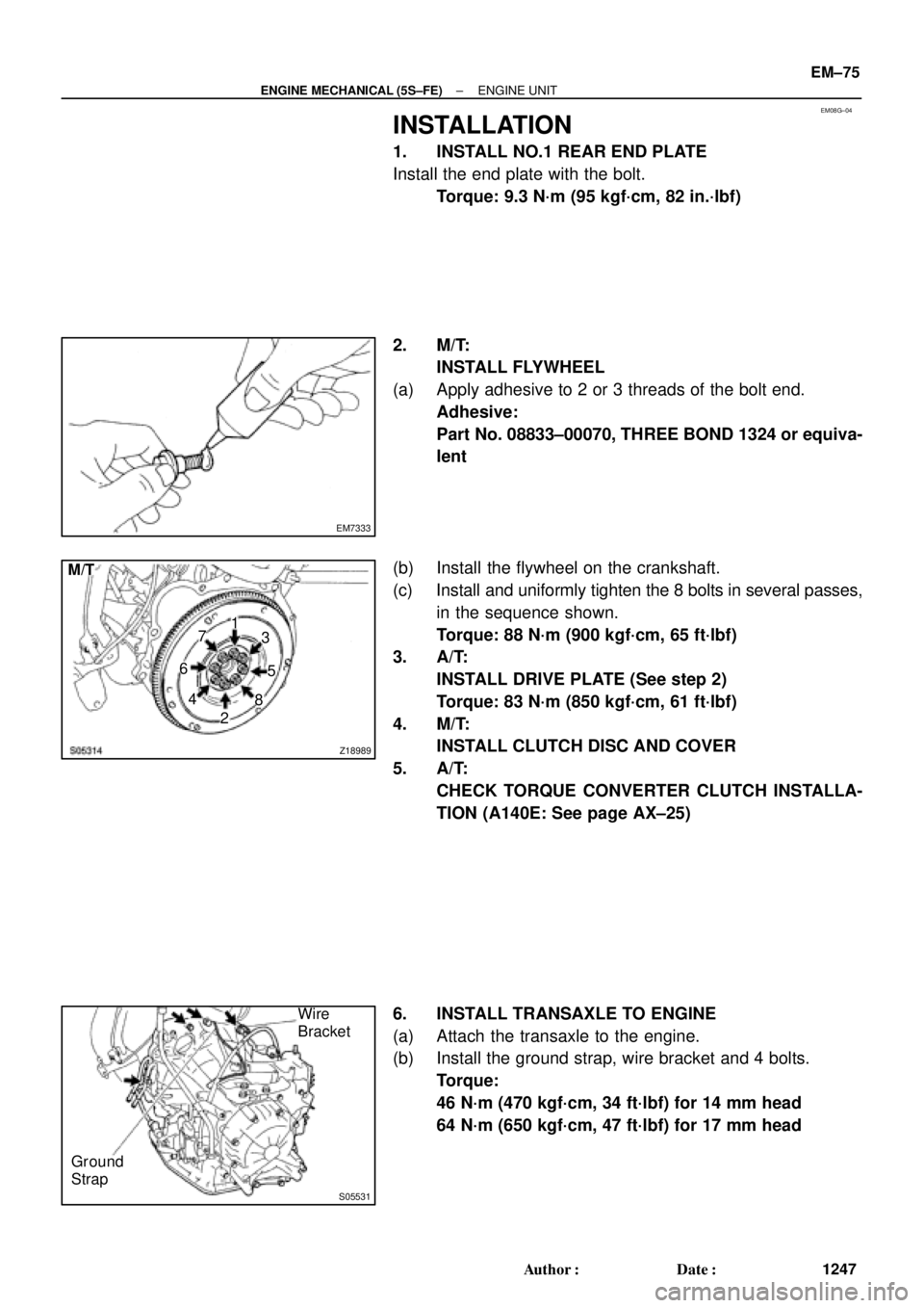
INSTALLATION
1. INSTALL NO.1 REAR END PLATE
Install the end plate with the bolt.
Torque: 9.3 N´m (95 kgf´cm, 82 in.´lbf)
2. M/T:
INSTALL FLYWHEEL
(a) Apply adhesive to 2 or 3 threads of the bolt end.
Adhesive:
Part No. 08833±00070, THREE BOND 1324 or equiva-
lent
(b) Install the flywheel on the crankshaft.
(c) Install and uniformly tighten the 8 bolts in several passes,
in the sequence shown.
Torque: 88 N´m (900 kgf´cm, 65 ft´lbf)
3. A/T:
INSTALL DRIVE PLATE (See step 2)
Torque: 83 N´m (850 kgf´cm, 61 ft´lbf)
4. M/T:
INSTALL CLUTCH DISC AND COVER
5. A/T:
CHECK TORQUE CONVERTER CLUTCH INSTALLA-
TION (A140E: See page AX±25)
6. INSTALL TRANSAXLE TO ENGINE
(a) Attach the transaxle to the engine.
(b) Install the ground strap, wire bracket and 4 bolts.
Torque:
46 N´m (470 kgf´cm, 34 ft´lbf) for 14 mm head
64 N´m (650 kgf´cm, 47 ft´lbf) for 17 mm head
Page 3468 of 4770
Z19014Turn
Black
Colored
Bolt A/T
S05530
A02198
S05526
TMC
Made
TMMK
Made
EM±76
± ENGINE MECHANICAL (5S±FE)ENGINE UNIT
1248 Author�: Date�:
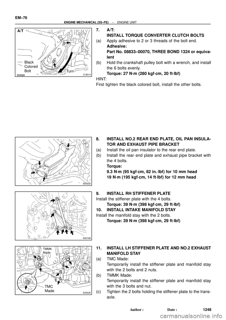
7. A/T:
INSTALL TORQUE CONVERTER CLUTCH BOLTS
(a) Apply adhesive to 2 or 3 threads of the bolt end.
Adhesive:
Part No. 08833±00070, THREE BOND 1324 or equiva-
lent
(b) Hold the crankshaft pulley bolt with a wrench, and install
the 6 bolts evenly.
Torque: 27 N´m (280 kgf´cm, 20 ft´lbf)
HINT:
First tighten the black colored bolt, install the other bolts.
8. INSTALL NO.2 REAR END PLATE, OIL PAN INSULA-
TOR AND EXHAUST PIPE BRACKET
(a) Install the oil pan insulator to the rear end plate.
(b) Install the rear end plate and exhaust pipe bracket with
the 4 bolts.
Torque:
9.3 N´m (95 kgf´cm, 82 in.´lbf) for 10 mm head
19 N´m (195 kgf´cm, 14 ft´lbf) for 12 mm head
9. INSTALL RH STIFFENER PLATE
Install the stiffener plate with the 4 bolts.
Torque: 39 N´m (398 kgf´cm, 29 ft´lbf)
10. INSTALL INTAKE MANIFOLD STAY
Install the manifold stay with the 2 bolts.
Torque: 39 N´m (398 kgf´cm, 29 ft´lbf)
11. INSTALL LH STIFFENER PLATE AND NO.2 EXHAUST
MANIFOLD STAY
(a) TMC Made:
Temporarily install the stiffener plate and manifold stay
with the 2 bolts and 2 nuts.
(b) TMMK Made:
Temporarily install the stiffener plate and manifold stay
with the 3 bolts and nut.
(c) Tighten the 2 bolts holding the stiffener plate to the trans-
axle.
Page 3762 of 4770
MX04C±01
Q09998
Hood
ClipCruise Control Actuator
Control Cable
Clutch Line
Bracket
Clutch Release CylinderWasher
RH Drive Shaft
Snap Ring
RH Stiffener
Plate
Ground Cable
Starter
Battery
Snap Ring
LH Drive Shaft�
RH Fender Apron
Seal
LH Stiffener Plate
Manifold StayTransaxle Back±Up Light Switch
Connector
Rear End Plate with Oil Pan
InsulatorAir Cleaner
Case Assembly
with Air Hose
Vehicle Speed Sensor
Connector
No.1 Fuel Tube Protector Engine LH
Mounting Insulator
with Bracket
Rear RH Suspension Member Brace
PS Gear Assembly
Lock Cap
Rear LH Suspension Member Brace Manifold StayClip
LH Fender Apron
Seal
Suspension Member with
Lower Suspension Arm
Front RH Suspension
Member BraceStabilizer Bar Link
Front Exhaust PipeCotter Pin
RH Fender
Liner
LH Fender Liner
Exhaust Pipe BracketNo.1 Exhaust Pipe
Support Bracket
: Specified torque
Non±reusable partGasket w/ Cruise Control:
�
�
�
Cotter Pin
�
Hole
Plug
�
�
Engine Rear Side Shutter PlateHold±Down
Clamp
Hole
Plug
12 (120, 9)
13 (130, 9)
46 (470, 34)
39 (400, 29)
6.9 (70, 61 in.´lbf)
14 (145, 10)
12 (120, 9)
39 (400, 29)
39 (400, 29)
64 (650, 47)
56 (570, 41)
37 (380, 27)
9.3 (95, 82 in.´lbf)
42 (425, 31)
32 (330, 24)
Silver Bolt: 44 (450, 33)
Green Bolt: 66 (670, 48)
62 (630, 46)
64 (650, 47)
64 (650, 47)
37 (380, 27)
181 (1,850, 134)
181 (1,850, 134)
181 (1,850, 134)
36 (370, 27)
10 (100, 7)
32 (330, 24)19 (195, 14)
49 (500, 36)
294 (3,000, 217)
Silver Bolt: 44 (450, 33)
Green Bolt: 66 (670, 48)
36 (370, 27)66 (670, 48)
39 (400, 29)
127 (1,300, 94)
33 (330, 24)
33 (330, 24)
19 (195, 14)
80 (820, 59)
Gasket�
�� �
Steering Return Pipe
Front LH
Suspension
Member Brace
N´m (kgf´cm, ft´lbf)
± MANUAL TRANSAXLE (S51)MANUAL TRANSAXLE UNIT
MX±3
1853 Author�: Date�:
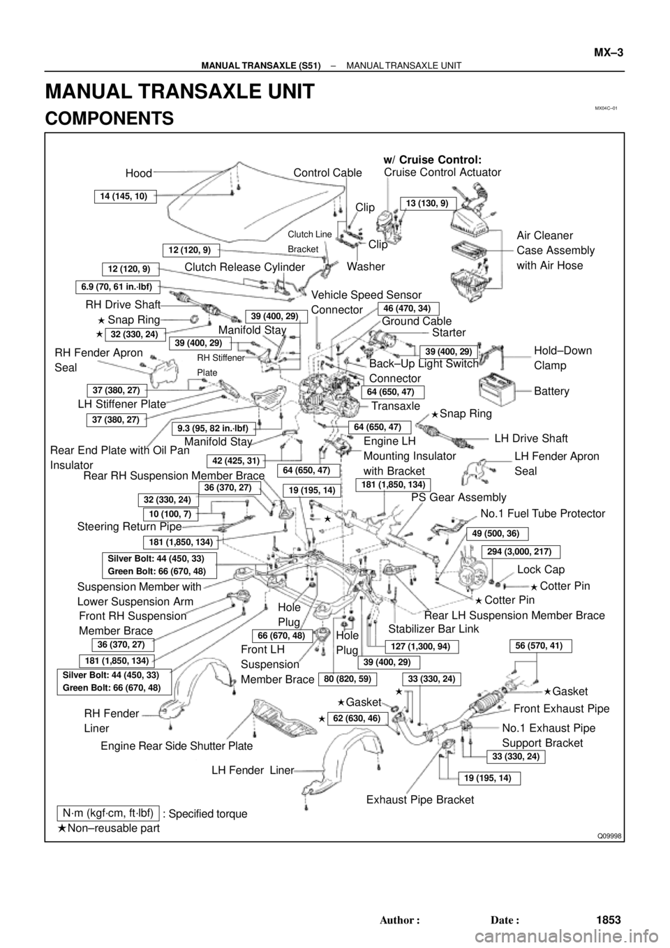
MANUAL TRANSAXLE UNIT
COMPONENTS