Page 1919 of 4770

AUTOMATIC TRANSAXLECOMPONENT PARTS INSTALLATION ±
AX±123
9. INSTALL OIL PIPES
Using a plastic hammer, install the pipes into the posi-
tions.
NOTICE: Be careful not to bend or damage the pipes.
10. INSTALL MANUAL VALVE BODY AND DETENT
SPRING
HINT: Each bolt length is indicated below.
Bolt length:
Bolt A: 22 mm (0.866 in.)
Bolt B: 37 mm (1.457 in.)
(a) Align the manual valve with the pin on the manual shaft
lever.
(b) Lower the manual valve body into place.
(c) Hand tighten the 5 bolts first. Then, tighten them with a
torque wrench.
Torque: 11 N´m (110 kgf´cm, 8 ft´lbf)
(d) Place the detent springs on the manual valve body and
hand tighten the 2 bolts first.
Then, tighten them with a torque wrench.
Torque: 11 N´m (110 kgf´cm, 8 ft´lbf)
HINT: Each bolt length is indicated below.
Bolt length:
Bolt A: 14 mm (0.551 in.)
Bolt B: 37 mm (1.457 in.)
(e) Check that the manual valve lever is touching the center
of the detent spring tip roller.
11. INSTALL PIPE BRACKET AND OIL STRAINER
Each bolt length is indicated below.
Bolt length:
Bolt A: 22 mm (0.866 in.)
Bolt B: 53 mm (2.087 in.)
Torque:
Pipe bracket: 10 N´m (100 kgf´cm, 7 ft´lbf)
Oil strainer: 11 N´m (110 kgf´cm, 8 ft´lbf)
Page 1920 of 4770
AUTOMATIC TRANSAXLECOMPONENT PARTS INSTALLATION ±
AX±124
12. INSTALL MAGNETS IN PLACE
NOTICE: Make sure that the magnets do not interfere with
the oil pipes.
13. INSTALL OIL PAN WITH NEW GASKET
(a) Install a new gasket and oil pan.
(b) Install and torque the 17 bolts.
Torque: 4.9 N´m (50 kgf´cm, 43 in.´lbf)
14. INSTALL THROTTLE CABLE RETAINING PLATE
15. INSTALL TRANSAXLE UPPER COVER
16. INSTALL T/M REVOLUTION SENSOR
(a) Install a new O±ring to the T/M revolution sensor.
(b) Install the T/M revolution sensor with the bolt.
Page 1921 of 4770
AUTOMATIC TRANSAXLECOMPONENT PARTS INSTALLATION ±
AX±125
17. INSTALL PARK/NEUTRAL POSITION SWITCH
(a) Install the park/neutral position switch to the manual valve
shaft.
(b) Place the new locking plate and tighten the nut.
(c) Stake the nut with locking plate.
(d) Install the 2 bolts.
(e) Adjust the park/neutral position switch.
HINT: Align the groove and neutral basic line.
(f) Tighten the 2 bolts.
18. INSTALL UNION AND ELBOW
(a) Install the new O±rings to the union and elbow.
(b) Install the union elbow to the transaxle case.
Torque: 27 N´m (275 kgf´cm, 20 ft´lbf)
HINT: Install the elbow, as shown in the illustration.
19. INSTALL MANUAL SHAFT LEVER
Page 1928 of 4770
AUTOMATIC TRANSAXLESERVICE SPECIFICATIONS ±
AX±132
TORQUE SPECIFICATIONS
Part tightenedN´mkgf´cmft´lbf
Oil cooler pipe union2727520
Oil pan4.95043 in.´lbf
Valve body x Transaxle case1111 08
Accumulator x Cover101007
Oil pump x Transaxle case2222516
O/D case x Transaxle case2525018
Differential LH side bearing retainer1919514
Differential RH retainer1919514
Differential carrier cover3940029
Oil pump body x Stator shaft101007
Ring gear x Differential case1241,26091
Upper valve body x Lower valve body6.66758 in.´lbf
Accumulator cylinder x Valve body6.66758 in.´lbf
Solenoid x Valve body6.66758 in.´lbf
Counter drive gear lock nut2802,855206
Carrire cover x Transaxle case3940029
Parking lock pawl bracket7.47565 in.´lbf
Oil strainer x Transaxle case1111 08
AX04N±03
Page 1931 of 4770
Q05725
AX03N±01
Q04678
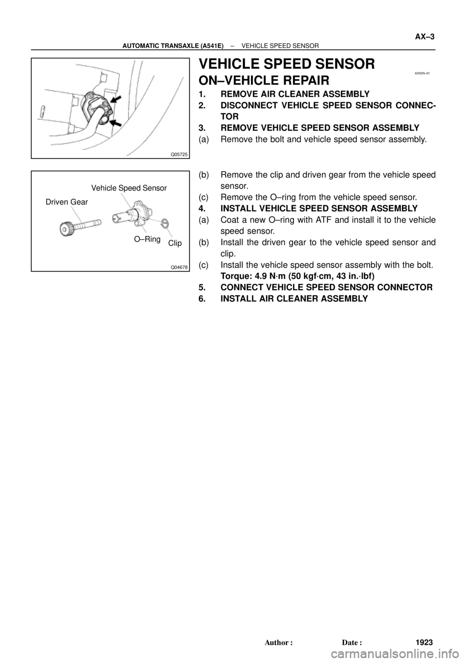
Clip O±Ring Driven GearVehicle Speed Sensor
± AUTOMATIC TRANSAXLE (A541E)VEHICLE SPEED SENSOR
AX±3
1923 Author�: Date�:
VEHICLE SPEED SENSOR
ON±VEHICLE REPAIR
1. REMOVE AIR CLEANER ASSEMBLY
2. DISCONNECT VEHICLE SPEED SENSOR CONNEC-
TOR
3. REMOVE VEHICLE SPEED SENSOR ASSEMBLY
(a) Remove the bolt and vehicle speed sensor assembly.
(b) Remove the clip and driven gear from the vehicle speed
sensor.
(c) Remove the O±ring from the vehicle speed sensor.
4. INSTALL VEHICLE SPEED SENSOR ASSEMBLY
(a) Coat a new O±ring with ATF and install it to the vehicle
speed sensor.
(b) Install the driven gear to the vehicle speed sensor and
clip.
(c) Install the vehicle speed sensor assembly with the bolt.
Torque: 4.9 N´m (50 kgf´cm, 43 in.´lbf)
5. CONNECT VEHICLE SPEED SENSOR CONNECTOR
6. INSTALL AIR CLEANER ASSEMBLY
Page 1932 of 4770
Q05726
AX03O±01
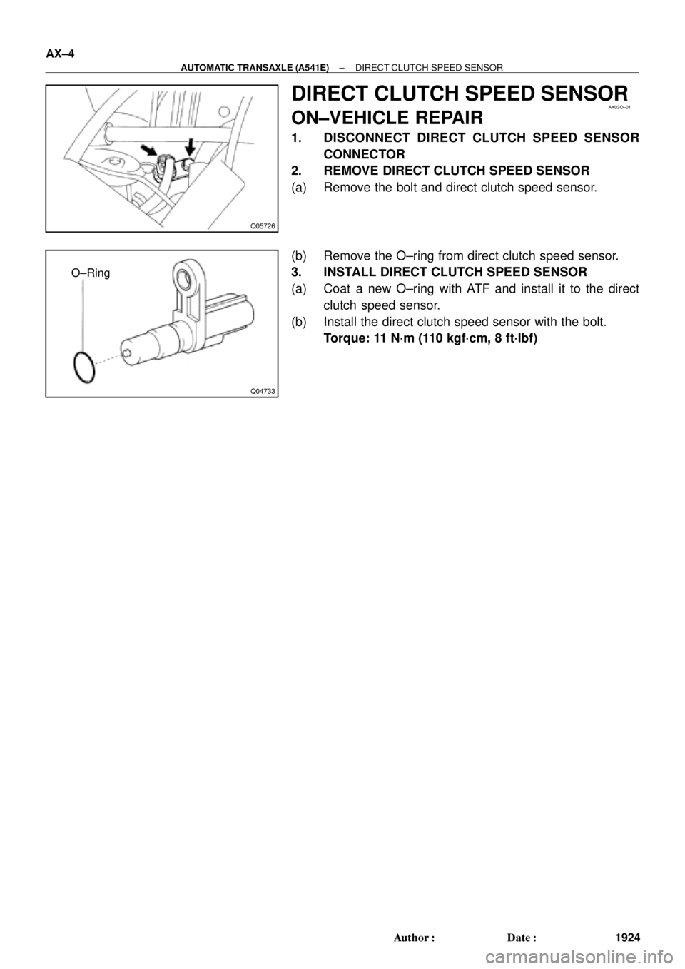
Q04733
O±Ring AX±4
± AUTOMATIC TRANSAXLE (A541E)DIRECT CLUTCH SPEED SENSOR
1924 Author�: Date�:
DIRECT CLUTCH SPEED SENSOR
ON±VEHICLE REPAIR
1. DISCONNECT DIRECT CLUTCH SPEED SENSOR
CONNECTOR
2. REMOVE DIRECT CLUTCH SPEED SENSOR
(a) Remove the bolt and direct clutch speed sensor.
(b) Remove the O±ring from direct clutch speed sensor.
3. INSTALL DIRECT CLUTCH SPEED SENSOR
(a) Coat a new O±ring with ATF and install it to the direct
clutch speed sensor.
(b) Install the direct clutch speed sensor with the bolt.
Torque: 11 N´m (110 kgf´cm, 8 ft´lbf)
Page 1933 of 4770
AX03P±01
Q00229
Q06496
Q05727
Q04617
± AUTOMATIC TRANSAXLE (A541E)PARK/NEUTRAL POSITION (PNP) SWITCH
AX±5
1925 Author�: Date�:
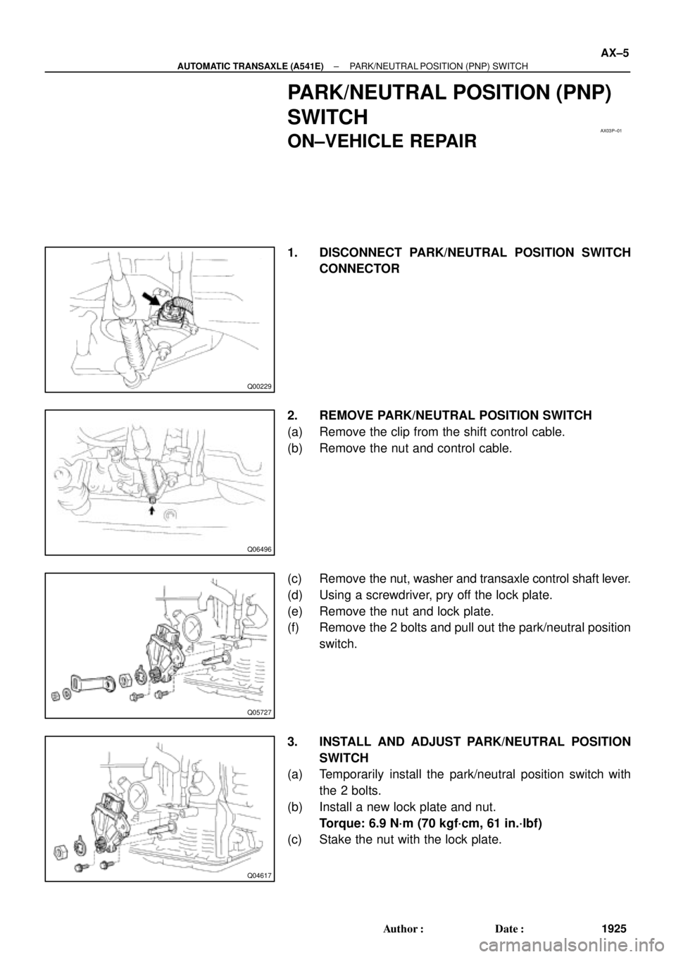
PARK/NEUTRAL POSITION (PNP)
SWITCH
ON±VEHICLE REPAIR
1. DISCONNECT PARK/NEUTRAL POSITION SWITCH
CONNECTOR
2. REMOVE PARK/NEUTRAL POSITION SWITCH
(a) Remove the clip from the shift control cable.
(b) Remove the nut and control cable.
(c) Remove the nut, washer and transaxle control shaft lever.
(d) Using a screwdriver, pry off the lock plate.
(e) Remove the nut and lock plate.
(f) Remove the 2 bolts and pull out the park/neutral position
switch.
3. INSTALL AND ADJUST PARK/NEUTRAL POSITION
SWITCH
(a) Temporarily install the park/neutral position switch with
the 2 bolts.
(b) Install a new lock plate and nut.
Torque: 6.9 N´m (70 kgf´cm, 61 in.´lbf)
(c) Stake the nut with the lock plate.
Page 1934 of 4770
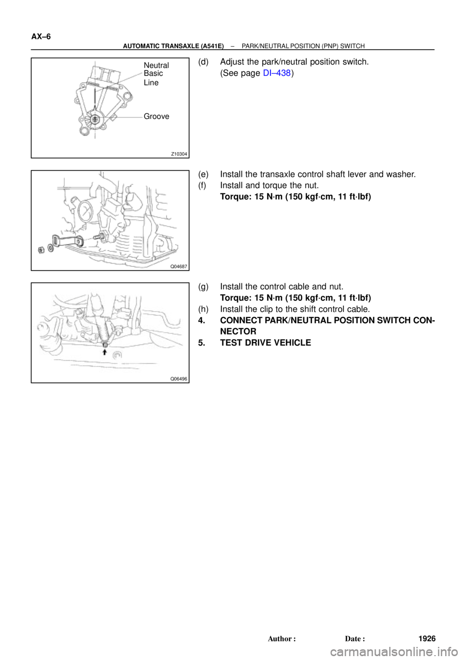
Z10304
Neutral
Basic
Line
Groove
Q04687
Q06496
AX±6
± AUTOMATIC TRANSAXLE (A541E)PARK/NEUTRAL POSITION (PNP) SWITCH
1926 Author�: Date�:
(d) Adjust the park/neutral position switch.
(See page DI±438)
(e) Install the transaxle control shaft lever and washer.
(f) Install and torque the nut.
Torque: 15 N´m (150 kgf´cm, 11 ft´lbf)
(g) Install the control cable and nut.
Torque: 15 N´m (150 kgf´cm, 11 ft´lbf)
(h) Install the clip to the shift control cable.
4. CONNECT PARK/NEUTRAL POSITION SWITCH CON-
NECTOR
5. TEST DRIVE VEHICLE
")
 Install the park/neutral position switch to the manual valve
shaft.
(b) Place the new locking pl")