2000 TOYOTA CAMRY starter ignition
[x] Cancel search: starter ignitionPage 1207 of 4770

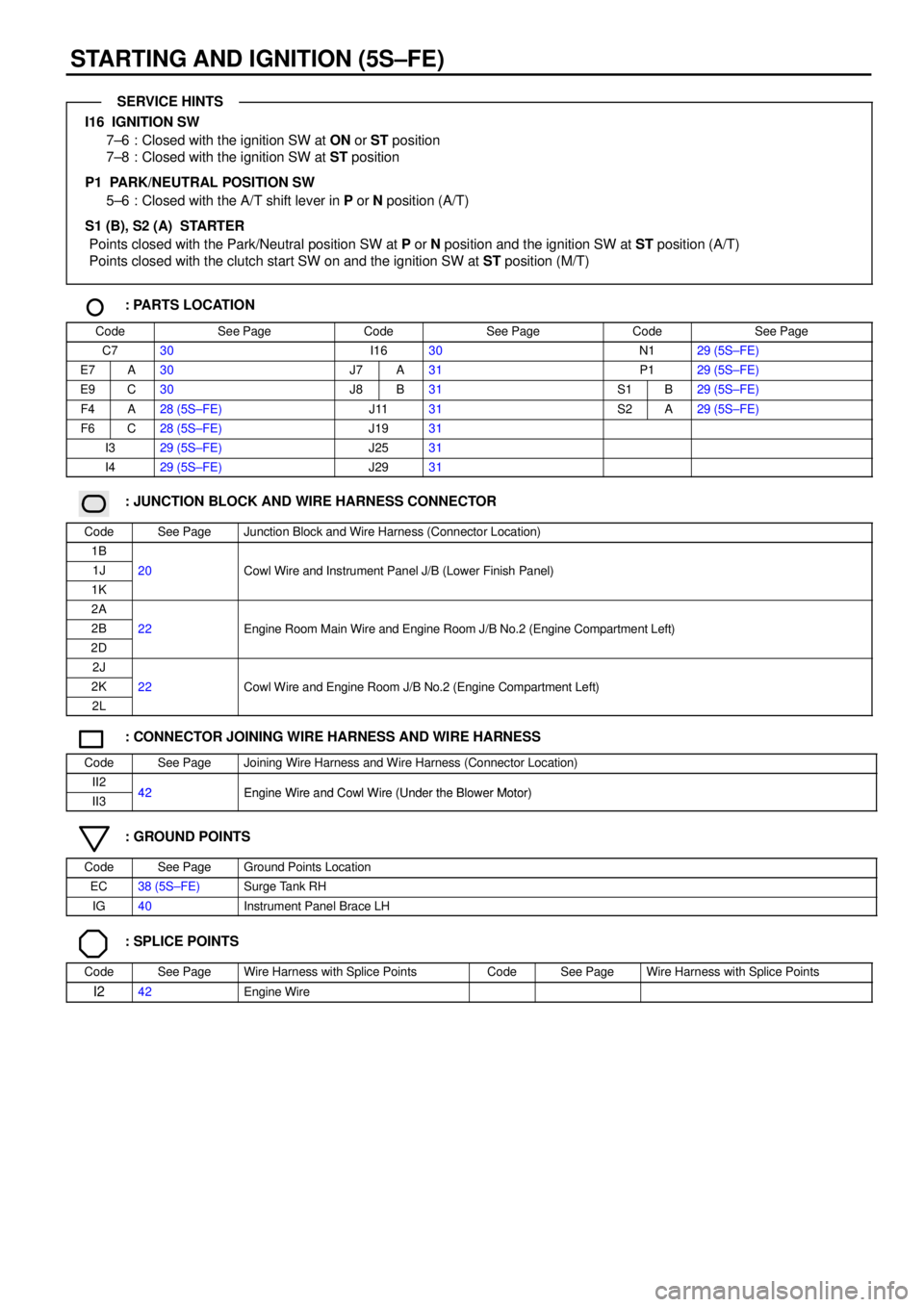
STARTING AND IGNITION (5S±FE)
I16 IGNITION SW
7±6 : Closed with the ignition SW at ON or ST position
7±8 : Closed with the ignition SW at ST position
P1 PARK/NEUTRAL POSITION SW
5±6 : Closed with the A/T shift lever in P or N position (A/T)
S1 (B), S2 (A) STARTER
Points closed with the Park/Neutral position SW at P or N position and the ignition SW at ST position (A/T)
Points closed with the clutch start SW on and the ignition SW at ST position (M/T)
: PARTS LOCATION
CodeSee PageCodeSee PageCodeSee Page
C730I1630N129 (5S±FE)
E7A30J7A31P129 (5S±FE)
E9C30J8B31S1B29 (5S±FE)
F4A28 (5S±FE)J1131S2A29 (5S±FE)
F6C28 (5S±FE)J1931
I329 (5S±FE)J2531
I429 (5S±FE)J2931
: JUNCTION BLOCK AND WIRE HARNESS CONNECTOR
CodeSee PageJunction Block and Wire Harness (Connector Location)
1B
1J20Cowl Wire and Instrument Panel J/B (Lower Finish Panel)
1K
()
2A
2B22Engine Room Main Wire and Engine Room J/B No.2 (Engine Compartment Left)
2D
gg(g)
2J
2K22Cowl Wire and Engine Room J/B No.2 (Engine Compartment Left)
2L
g(g )
: CONNECTOR JOINING WIRE HARNESS AND WIRE HARNESS
CodeSee PageJoining Wire Harness and Wire Harness (Connector Location)
II242Engine Wire and Cowl Wire (Under the Blower Motor)II342Engine Wire and Cowl Wire (Under the Blower Motor)
: GROUND POINTS
CodeSee PageGround Points Location
EC38 (5S±FE)Surge Tank RH
IG40Instrument Panel Brace LH
: SPLICE POINTS
CodeSee PageWire Harness with Splice PointsCodeSee PageWire Harness with Splice Points
I242Engine Wire
SERVICE HINTS
Page 1213 of 4770

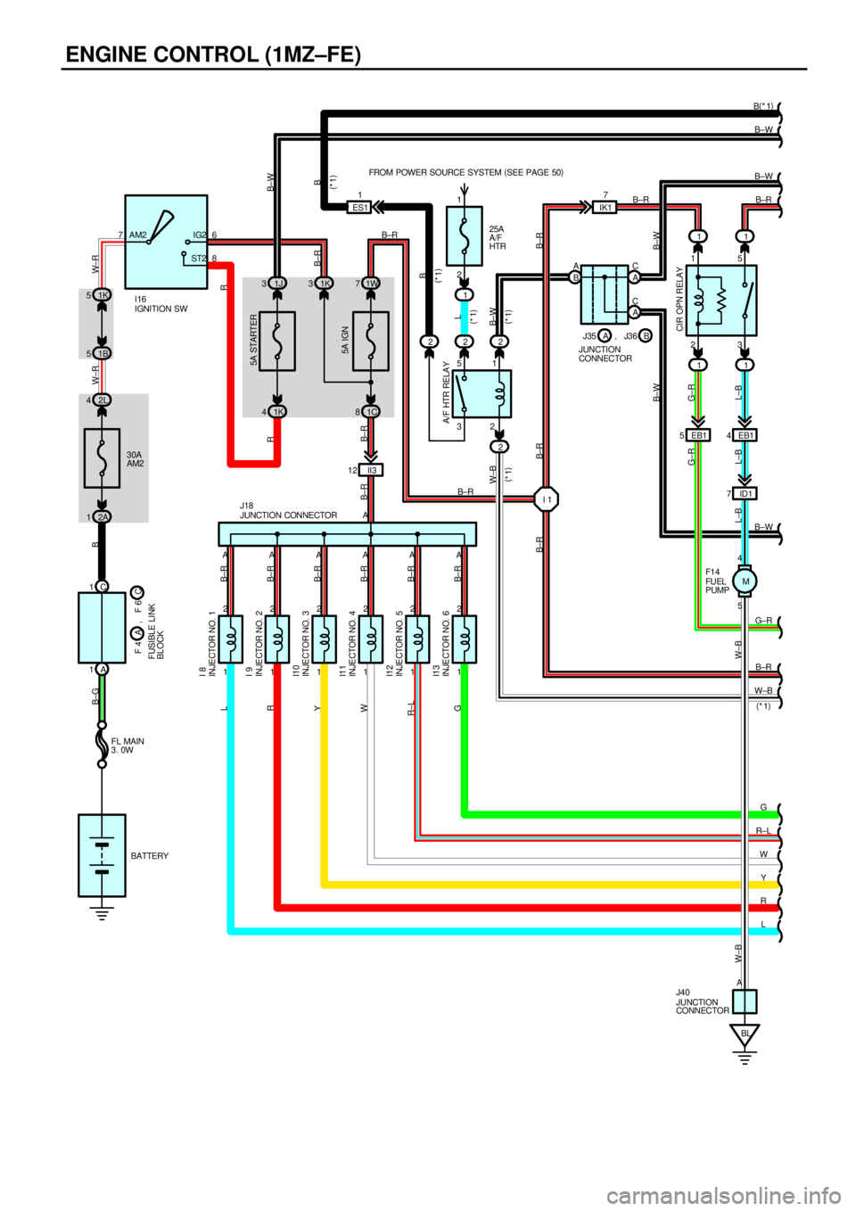
ENGINE CONTROL (1MZ±FE)
76
8 AM2 IG2
ST2
30A
AM2
5A IGN
1K 5
2L 41W 7 1K 311
1B 5
2A 11C 811
EB1 5
II3 12EB1 4
ID1 7
1 2
1 2
1 2
1 2
1 2
1 25 4 23 15
C 1
A 1
BL AAAAAAA
AG± R
G
R±L
W
Y
R
L B±R B(
*1)
B±R
B±RB±W W± R B B±GW±R
L±B L±B L±B W±BG±RB±R B±R
B±R B±R B±R B±R B±R B±R
G R±LWY RL
G±R
1J 3
1K 4
R
IGNITION SW
CIR OPN RELAY
JUNCTION CONNECTOR
JUNCTION
CONNECTORFUEL
PUMP I16
J18
F1 4
J40
INJECTOR NO. 1
INJECTOR NO. 2
INJECTOR NO. 3
INJECTOR NO. 4
INJECTOR NO. 5
INJECTOR NO. 6 I 8
I 9
I10
I11
I12
I13FUSIBLE LINK
BLOCKC F 4 F 6A
FL MAIN
3. 0W
BATTERY
5A STARTER
B±R
,
32 5125A
A/F
HTR FROM POWER SOURCE SYSTEM (
SEE PAGE 50)
1
2 2 2
W±BA/F HTR RELA Y
ES11B±W
B
B
B±W B±W
B A
A C
A C
J35
JUNCTION
CONNECTORB A,
L
B±W
B±W B±W W±B
2R
B±R
J3 6
(
*1)(
*1)
(
*1)
(
*1) (
*1)
1
2IK17
I 1 B±R
B±R B±RB±R
(
*1)
W±B
M
Page 1220 of 4770

This system utilizes an engine control module and maintains overall control of the engine, transmission and so on. An outline
of the engine control is explained here.
1. INPUT SIGNALS
(1) Engine coolant temp. signal circuit
The engine coolant temp. sensor detects the engine coolant temp. and has a built±in thermistor with a resistance which
varies according to the water temp. is input into TERMINAL THW of the engine control module as a control signal.
(2) Intake air temp. signal circuit
The intake air temp. sensor is installed in the mass air flow meter and detects the intake air temp., which is input as a
control signal into TERMINAL THA of the engine control module.
(3) Oxygen sensor signal circuit
The oxygen density in the exhaust gases is detected and input as a control signal into TERMINALS OXL1, OXR1
(Except California) and OXS of the engine control module. To maintain stable detection performance by the heated
oxygen sensor, a heater is used for warming the sensor. The heater is also controlled by the engine control module
(HTL, HTR (Except California) and HTS).
(4) RPM signal circuit
Camshaft position and crankshaft position are detected by the camshaft position sensor and crankshaft position sensor.
The camshaft position is input as a control signal to TERMINAL G22+ of the engine control module, and the engine
RPM is input into TERMINAL NE+.
(5) Throttle signal circuit
The throttle position sensor detects the throttle valve opening angle as a control signal, which is input into TERMINAL
VTA1 of the engine control module.
(6) Vehicle speed signal circuit
The vehicle speed sensor, installed inside the transmission, detects the vehicle speed and inputs a control signal into
TERMINAL SPD of the engine control module.
(7) Park/Neutral position SW signal circuit
The Park/Neutral position SW detects whether the shift position is in neutral, parking or not, and inputs a control signal
into TERMINAL STA of the engine control module.
(8) A/C SW signal circuit
The A/C control assembly (Automatic A/C) or A/C Amplifier (Manual A/C) inputs the A/C operations into TERMINAL A/C
of the engine control module as a control signal.
(9) Battery signal circuit
(California or w/ engine immobiliser and/or traction control)
Voltage is always supplies to TERMINAL BATT of the engine control module.
If you turn on the ignition SW, the current goes from TERMINAL MREL of the engine control module to the EFI relay and
put on the relay, and the voltage related to the engine control module operation is supplied to TERMINAL +B of the
engine control module through the EFI relay.
(Except California or w/ engine immobiliser and/or traction control)
Voltage is constantly applied to TERMINAL BATT of the engine control module. When the ignition SW is turned on,
voltage for engine control module start±up power supply is applied to TERMINAL +B of engine control module via EFI
relay.
(10) Intake air volume signal circuit
Intake air volume is detected by the mass air flow meter and a signal is input into TERMINAL VG of the engine control
module as a control signal.
(11) NSW signal circuit
To confirm whether the engine is cranking, the voltage applied to the starter motor during cranking is detected and the
signal is input into TERMINAL NSW of the engine control module as a control signal.
(12) Engine knock signal circuit
Engine knocking is detected by the knock sensor 1 and 2, then the signals are input into TERMINALS KNKR and KNKL
of the engine control module as a control signal.
(13) Air fuel ratio signal circuit (California)
The air fuel ratio is detected and input as a control signal into TERMINALS AFL+, AFR+ of the engine control module.
SYSTEM OUTLINE
Page 1223 of 4770
![TOYOTA CAMRY 2000 Service Repair Manual ENGINE CONTROL (1MZ±FE)
I8, I9, I10, I11, I12, I13 INJECTOR
2±1 : Approx. 13.8 W
CIR OPN RELAY [R/B NO.1]
3±5 : Closed with starter running
EFI RELAY [ENGINE ROOM J/B NO.2]
3±5 : Closed with igni TOYOTA CAMRY 2000 Service Repair Manual ENGINE CONTROL (1MZ±FE)
I8, I9, I10, I11, I12, I13 INJECTOR
2±1 : Approx. 13.8 W
CIR OPN RELAY [R/B NO.1]
3±5 : Closed with starter running
EFI RELAY [ENGINE ROOM J/B NO.2]
3±5 : Closed with igni](/manual-img/14/57447/w960_57447-1222.png)
ENGINE CONTROL (1MZ±FE)
I8, I9, I10, I11, I12, I13 INJECTOR
2±1 : Approx. 13.8 W
CIR OPN RELAY [R/B NO.1]
3±5 : Closed with starter running
EFI RELAY [ENGINE ROOM J/B NO.2]
3±5 : Closed with ignition SW at ON or ST position
: PARTS LOCATION
CodeSee PageCodeSee PageCodeSee Page
A12C30H830J2431
A2826 (1MZ±FE)H326 (1MZ±FE) J2631
A2926 (1MZ±FE)H426 (1MZ±FE)J27A31
A34A30I127 (1MZ±FE)J28B31
A35B30I827 (1MZ±FE) J2931
C126 (1MZ±FE)I927 (1MZ±FE)J35A31
C226 (1MZ±FE) I1027 (1MZ±FE)J26B31
C730I1127 (1MZ±FE)J4032
C9B30I1227 (1MZ±FE)K127 (1MZ±FE)
C10C30I1327 (1MZ±FE)K227 (1MZ±FE)
D126 (1MZ±FE) I1630M227 (1MZ±FE)
D530J331P127 (1MZ±FE)
E126 (1MZ±FE) J431P227 (1MZ±FE)
E226 (1MZ±FE) J7A31S631
E526 (1MZ±FE)J8B31T227 (1MZ±FE)
E7A30J9A31T331
E8B30J10B31U131
E9C30J1131V127 (1MZ±FE)
E10D30J1231V227 (1MZ±FE)
E11E30J1531V427 (1MZ±FE)
F4A26 (1MZ±FE)J1831V527 (1MZ±FE)
F6C26 (1MZ±FE)J2031V627 (1MZ±FE)
F1432 J2231V727 (1MZ±FE)
: RELAY BLOCKS
CodeSee PageRelay Blocks (Relay Block Location)
124Engine Room R/B No.1 (Engine Compartment Left)
224Engine Room R/B No.2 (Near the Battery)
Page 1230 of 4770

23 15P
N5
6
I 2 15A
EFI FROM POWER SOURCE
SYSTEM (
SEE PAGE 50)
EBEC
5A STARTER
1K 4
2K 7
2F 42C10
B EBB
A 14 D7A1C9C10 C17 C 23 C22 A 12A B
A 1A22 A11 1J 3
4 1 4 1
A2 3 3 2 B
B±Y Y W B±R(
*1) B±W(
*1) G±RB± RR
B±Y
B±W
B±O B±W
B± Y
B±Y
Y± R W±R W±RBB± Y B±Y
B±WB± Y
B±YB±R
W±B W±B
B±W
B±W
GR
B±O B±O GR(
*3)
GR BR B±RBRG±R
B±W
B± R
W
Y
W±R
B
FC #40 #30 #20 #10 IGT1 IGF IGT2+B BATT NSW STA(
*4 M/T)
(
*4 A/T) (
*4)
(
A/ T)
(
A/ T)
(
M/T)PARK/NEUTRA
LPOSITION SW
JUNCTION
CO NNE CTOR EFI
RE LA Y
J29P 1
* 1 : W/ ENGINE IMMOBILISER SYSTEM
* 2 : W/O ENGINE IMMOBILISER SYSTEM* 3 : TMC MADE
* 4 : TMMK MADEJUNCTION
CONNECTOR
IGNITION COIL AND
IGNITER NO. 1
IGNITION COIL AND
IGNITER NO. 2
J19
I 3
I 4
A A
BRB±R
2 1
CLUTCH START SW C 7II2 10 II2 11
E 3B±Y
BB
B JUNCTION
CO NNE CTOR J25
B± RIGTIGF IGFIGT
+B GND GND+B
II3 13
B±R B± RC 12 C 11 MREL IGSW
R
LA 14 C24 C25 C11 C12 C3 C 20 C19(
*1)
(
*2)
R (
*1)
L (
*1)
B±Y
II3 9
(
A/ T) (
*3 A/T)
A EAEABB B±W(
*2)
(
*1)
2J8
2J2
A 11 B± Y
A 12 A2A22(
*1)
(
*2)(
*1)
(
*2)
J27
JUNCTION CONNECTORB A, J28
E 7
ENGINE CONTROL MODULEB A, E 8 C, E 9 D, E10 2C 5W±B W±B
A BB CBC GR(
*3 M/T)J 7
JUNCTION
CONNECTORB A, J 8 B±W B±W
B±W
(
A/T)
Page 1235 of 4770

ENGINE CONTROL (5S±FE)
This system utilizes an engine control module and maintains overall control of the engine, transmission and so on. An outline
of the engine control is explained here.
1. INPUT SIGNALS
(1) Engine coolant temp. signal circuit
The engine coolant temp. sensor detects the engine coolant temp. and has a built±in thermistor with a resistance which
varies according to the engine coolant temp. thus the engine coolant temp. is input in the form of a control signal into
TERMINAL THW of the engine control module.
(2) Intake air temp. signal circuit
The intake air temp. sensor detects the intake air temp., which is input as a control signal into TERMINAL THA of the
engine control module.
(3) Oxygen sensor signal circuit
The oxygen density in the exhaust gases is detected and input as a control signal into TERMINAL OX1 (except
California) and OX2 of the engine control module.
(4) RPM signal circuit
Camshaft position and crankshaft position are detected by the camshaft position sensor and crankshaft position sensor.
Camshaft position is input as a control signal to TERMINAL G+ of the engine control module, and engine RPM is input
into TERMINAL NE+.
(5) Throttle signal circuit
The throttle position sensor detects the throttle valve opening angle, which is input as a control signal into TERMINAL
VTA of the engine control module.
(6) Vehicle speed signal circuit
The vehicle speed sensor, installed inside the transmission, detects the vehicle speed and inputs a control signal into
TERMINAL SPD of the engine control module.
(7) Park/Neutral position SW signal circuit (A/T)
The Park/Neutral position SW detects whether the shift position are in neutral, parking or not, and inputs a control signal
into TERMINAL STA of the engine control module.
(8) A/C SW signal circuit
The A/C amplifier function is built in the engine control module. The A/C SW signal inputs into the TERMINAL A/C SW of
the engine control module.
(9) Battery signal circuit
Voltage is constantly applied to TERMINAL BATT of the engine control module. When the ignition SW is turned on, the
voltage for engine control module start±up power supply is applied to TERMINAL +B of engine control module via EFI
relay.
(10) Intake air volume signal circuit
Intake air volume is detected by the manifold absolute pressure sensor (for manifold pressure) and is input as a control
signal into TERMINAL PIN of the engine control module.
(11) Starter signal circuit
To confirm whether the engine is cranking, the voltage applied to the starter motor during cranking is detected and the
signal is input into TERMINAL NSW of the engine control module as a control signal.
(12) Engine knock signal circuit
Engine knocking is detected by knock sensor 1 and the signal is input into TERMINAL KNK as a control signal.
(13) Electrical load signal circuit
The signal when systems such as the rear window defogger, headlights, etc. Which cause a high electrical burden are
on is input to TERMINAL ELS as a control signal.
(14) Air fuel ratio signal circuit (California)
The air fuel ratio is detected and input as a control signal into TERMINAL AF+ of the engine control module.
SYSTEM OUTLINE
Page 1471 of 4770

J OVERALL ELECTRICAL WIRING DIAGRAM
9
1011 12
3 CAMRY (
Cont ' d)
ECIntake
man i f ol d ST P 4A
LOCK IN18 C
PRS 13 A
G±WW± LG
MGC 21 AL±YA/ C SW 10 AR±B
LOCK 15 AR± W
NS W 22 AB±W
STA 11 A
GR(
*5)
B±O(
*6)
IGT1 20 CB
IGF 3CW±R
IGT2 19 CY±R
10 II3
W± L
TE1 15 B From Ignition Coil
and Igniter
No. 1, No. 2< 1±3> < 1±4>
12 DNE+
1 2
C 2
CRANKSHAFT
POSI TI ON SENSOR
1 2C 1
CAMSHAFT
POSI TI ON SENSOR6DNE±
11 DG+
12 BKNK
25 CE03
26 CE02
13 CE01
8ASPD
7A15 CE04
To Speedometer
[Comb. Meter]
< 25±8> L
EC Intake
ma ni f o ldBR
B±YBR BR BR(
*4)
BR BR
BR
BR
BR
B±RBRL B±W W
1
(
Shielded) (
Shielded) (
Shielded)BR
BR
BRBR
BR A
A
AA
A
A
AJ23
JUNCTION
CONNECTOR
BR
V± W BR BR
BR
(
*3)
(
*4) TE1 E1+B
L±W
From St op Light
SW< 11±4> To A/ C Magnetic
Clutc h and Loc k
Sens or < 27±4>From A/C Dual
Pressure SW< 27±4>Fr om MG CL T
Relay< 27±3>Fro m A/ C SW
< 27±4> Fro m A/ C SW
< 27±4> Fr om º STARTERº
Fuse< 1±2> From Park/Neut ral Position
SW(
A/ T)
or Clutc h Star t
SW(
M/ T)
< 1±2>12
83D 1
DATA LINK
CONNECTOR 1* 3 : Califor nia
* 4 : Exc ept Calif or nia * 2 : w/o Engine Immobiliser SystemBR BR
24 CE1
BR
(
*3)
ENGINE CONTROL MODULE
A
6II3
Engine Control and Engine Immobiliser System (
5S±FE)BR
BR
BR
BR
G L(
*5)
W(
*6) W
BR
A1 1
AI R F UEL
RA TI O SE NSORHTAF 2C
AF± 14 B
AF + 6B
OX1 6B
HT1 8C 14 23
31 24
H 3
HEAT ED OXYGEN SENSOR
(
Bank 1 Sens or 1)
(
*3) B±W(
*5)
O (
*6)
(
*3) (
*3) (
Shielded) (
Shielded) (
*4) L±Y
(
*4)
HTE1
OX+B
HT AF±+B AF+ A
B
C
D
EB B±Y B±Y
(
*4)
(
*3)
B±Y
(
*4)
1DIMLD
4DKSW
3II4
4IG3 8IG3
To Theft
Det er rent
System< 15±3>To Un l oc k
War ning SW
< 21±3>R±YL±B
R±YL±B
R± YL±B
BR(
*2) 9A 19C 19A 21A 10A 20A 22A 11A 23C 17C 22C 7B 2C14B6B 5B1C(
*1)
9A 8A 4C 17C 5C 13B 15C 14C2DEOM
BR
A16 B 26 C 13 C(
*2) (
*1)
(
*2)* 5 : TMC Made
* 6 : TMMK Made
(
*4)
FA
To Tac hometer
[Comb. Meter]
< 25±5>FA
B±O B±OTACH
JUNCTION
CONNECTORJ27 A
* 1 : w/ Engine Immobiliser System
, E 8 E 7 A B , E 9 C , E10 D
9II4
(
A/T)
K 1
KNOCK SENSOR 1
Page 1505 of 4770

K POWER SOURCE (Current Flow Chart)
Fusible Link Block (See Page 19)
FuseSystemPage
50AHTRAir Conditioning (Automatic A/C)
Air Conditioning (Manual A/C)292
300
100AALT
Charging
Headlight (w/ Daytime Running Light)
Illumination
Light Auto Turn Off
Radiator Fan and Condenser Fan
Taillight
Theft Deterrent (TMC Made)
Theft Deterrent (TMMK Made)
Wireless Door Lock Control (TMC Made)
Wireless Door Lock Control (TMMK Made)62
100
126
11 0
288
132
182
188
162
172
Instrument Panel J/B (See Page 20)
FuseSystemPage
5AIGN
Charging
Combination Meter
Electronically Controlled Transmission and A/T Indicator (1MZ±FE)
Electronically Controlled Transmission and A/T Indicator (5S±FE)
Engine Control (1MZ±FE)
Engine Control (5S±FE)
SRS62
280
202
210
66
82
245
5ASTARTER
Combination Meter
Electronically Controlled Transmission and A/T Indicator (1MZ±FE)
Electronically Controlled Transmission and A/T Indicator (5S±FE)
Engine Control (1MZ±FE)
Engine Control (5S±FE)
Starting and Ignition (1MZ±FE)
Starting and Ignition (5S±FE)280
202
210
66
82
54
58
7.5AOBDEngine Control (1MZ±FE)
Engine Control (5S±FE)66
82
7.5APANEL
Cigarette Lighter and Clock
Combination Meter
Illumination258
280
126
7.5ARAD±NO.2
Auto Antenna
Radio and Player (Built±In Type Amplifier)
Radio and Player (Separate Type Amplifier)272
278
274
7.5ATURNTurn Signal and Hazard Warning Light11 4
10AGAUGE
ABS (TMC Made)
ABS (TMMK Made)
ABS and Traction Control
Back±Up Light
Charging234
240
226
138
62
*These are the page numbers of the first page on which the related system is shown.