Page 2796 of 4770
A00244
ON
BE6653
P20186
DI±376
± DIAGNOSTICSENGINE (1MZ±FE)
611 Author�: Date�:
INSPECTION PROCEDURE
TOYOTA hand±held tester
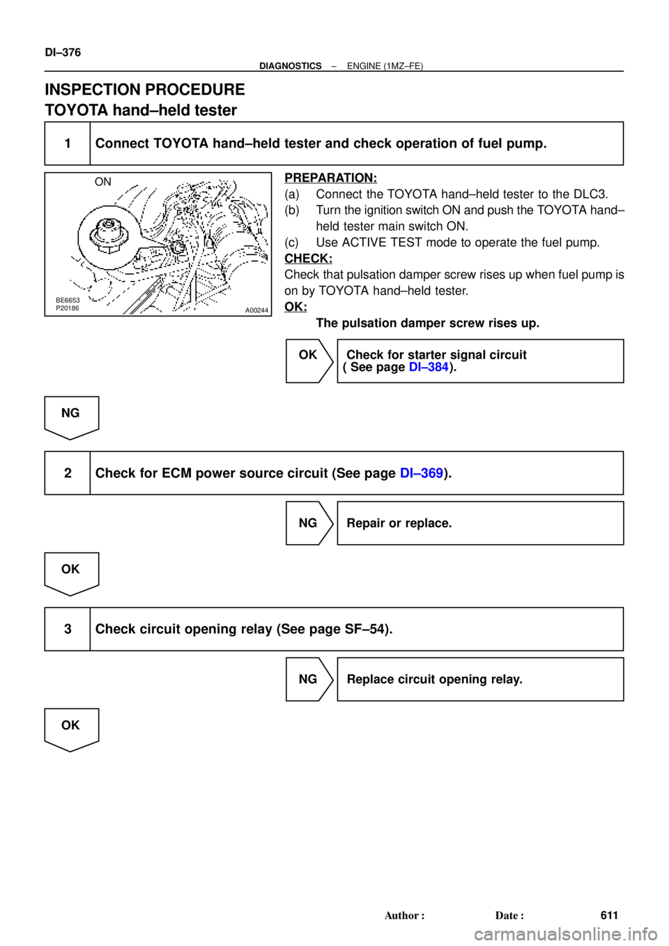
1 Connect TOYOTA hand±held tester and check operation of fuel pump.
PREPARATION:
(a) Connect the TOYOTA hand±held tester to the DLC3.
(b) Turn the ignition switch ON and push the TOYOTA hand±
held tester main switch ON.
(c) Use ACTIVE TEST mode to operate the fuel pump.
CHECK:
Check that pulsation damper screw rises up when fuel pump is
on by TOYOTA hand±held tester.
OK:
The pulsation damper screw rises up.
OK Check for starter signal circuit
( See page DI±384).
NG
2 Check for ECM power source circuit (See page DI±369).
NG Repair or replace.
OK
3 Check circuit opening relay (See page SF±54).
NG Replace circuit opening relay.
OK
Page 2798 of 4770
A02042
ON
FC
DI±378
± DIAGNOSTICSENGINE (1MZ±FE)
613 Author�: Date�:
OBD II scan tool (excluding TOYOTA hand±held tester)
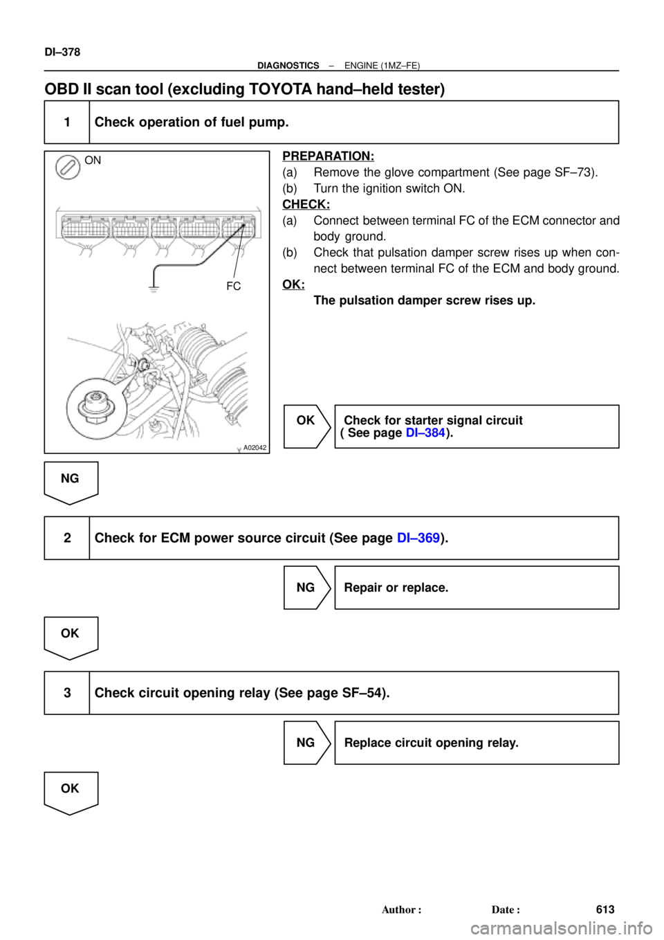
1 Check operation of fuel pump.
PREPARATION:
(a) Remove the glove compartment (See page SF±73).
(b) Turn the ignition switch ON.
CHECK:
(a) Connect between terminal FC of the ECM connector and
body ground.
(b) Check that pulsation damper screw rises up when con-
nect between terminal FC of the ECM and body ground.
OK:
The pulsation damper screw rises up.
OK Check for starter signal circuit
( See page DI±384).
NG
2 Check for ECM power source circuit (See page DI±369).
NG Repair or replace.
OK
3 Check circuit opening relay (See page SF±54).
NG Replace circuit opening relay.
OK
Page 2804 of 4770

A07453
5
1B±R
1ECM Engine Room J/B
E77
STA
E1 S2
Starter W±B 9 5
2D
2K 3
2
Sarter Relay MAIN
2B3
2J 11 B
J7
J7 J8
Junction
Connector CB
B II210 From Battery
W±B
W±B
A
A J11
Junction
Connector
IG Instrument
Panel J/B
STARTER
From Ignition Switch11
II2
B±W(A/T)
B±W(A/T)
B±W
Park/Neutral
Position Switch 6
5
B±W(A/T)
B
B
B
1J
1K 3
4
B±W(M/T)
12
Clutch Start Switch
GR
*1GR1
*1B±O
*GR
*GR
*GR
*B±O(M/T)
J16
Junction
Connector
*B±O
*: TMMK made
*
1: TMC made
*1B±O
DI±384
± DIAGNOSTICSENGINE (1MZ±FE)
619 Author�: Date�:
Starter Signal Circuit
CIRCUIT DESCRIPTION
When the engine is cranked, the intake air flow is slow, so fuel vaporization is poor. A rich mixture is therefore
necessary in order to achieve good startability. While the engine is being cranked, the battery positive volt-
age is applied to terminal STA of the ECM. The starter signal is mainly used to increase the fuel injection
volume for the starting injection control and after±start injection control.
WIRING DIAGRAM
DI08B±06
Page 2805 of 4770
± DIAGNOSTICSENGINE (1MZ±FE)
DI±385
620 Author�: Date�:
INSPECTION PROCEDURE
HINT:
This diagnostic chart is based on the premise that the engine is cranked normally. If the engine is not
cranked, proceed to the problem symptoms table on page DI±221.
TOYOTA hand±held tester
1 Connect TOYOTA hand±held tester, and check STA signal.
PREPARATION:
(a) Connect the TOYOTA hand±held tester to the DLC3.
(b) Turn the ignition switch ON and push the TOYOTA hand±held tester main switch ON.
CHECK:
Read STA signal on the TOYOTA hand±held tester while starter operates.
OK:
Ignition switch positionONSTART
STA signalOFFON
OK Proceed to next circuit inspection shown on
problem symptom table (See page DI±221).
NG
2 Check for open in harness and connector between ECM and starter relay
(See page IN±31).
NG Repair or replace or connector.
OK
Check and replace ECM (See page IN±31).
Page 2845 of 4770

D01820
Combination
Meter
R
C8R ± B
13
IG13
2
L8
11
6 C8
C8O
Y16
IG13
*3 L ± W
*4 O
1HInstrument
Panel J/BECM
1V Park/Neutral
Position Switch
P1
L ± W
B ± WII2
E
8 34
P1
P1 P12Y
R ± BII2
J29
Junction
Connector E
E
Y10
5
Y19
15
*1
*2
E7
E7
E7
E7
E7
E7R2 L
1816
*1
*2
17
22B
+
NSW *3 L ± W
*4 O
R ± B
R ± B
B ± W
DD
D
J29
Junction
Connector
J27J27
J28 CC
A
R ± B
B ± W 5
6
3
11II3
II2
B
BB R ± L A
A
J21
Junction
Connector
J28
Junction
Connector
5 2II2R ± L
F
F6
B ± R
F9
ALT
B ± G
B ± R
1
112F9
F4F6
FL
MAIN
BatteryAM1
1B
2L12
55 1B
1K1K
2A 41
AM2 W ± R
B GR
II2
W ± R
10*5
*6GR
B ± O
C
J8B*5
*6GR
B ± O
BW2
74
8 I16 I16
I16 I16Ignition Switch
B ± Y
R11
43 1K
1K1J
1J GAUGE
STARTER
MAINST Relay
2BB ± W
3
115
9
2J2D
2K 5
3
12 Y
J29
Junction
Connector
J27, J28
Junction Connector
*3 L ± W
*4 O
Instrument Panel J/B
Instrument Panel J/B Instrument Panel J/B
Engine Room J/B No.2
J11 Junction Connector
*1: w/ Engine Immobiliser System
*2: w/o Engine Immobiliser System
*3: TMC Made*4: TMMK Made
*5: TMC Made w/o Traction Control
*6: Except TMC Made w/o Traction ControlInstrument Panel J/B
Starter
J7A
IK R ± L
J7 J8 Junction Connector Engine Room J/B No.2 R ± L
± DIAGNOSTICSAUTOMATIC TRANSAXLE (A140E)
DI±425
660 Author�: Date�:
WIRING DIAGRAM
Page 2900 of 4770

D01897
Combination Meter
Ignition Switch Except California, w/ Engine Immobilizer and / or TRAC:
R
2
L8
11
6 C8
13
165
R±B
L±W YIJ1
IG310
1H
1VECM
1
E7
B+ 4
II2 P1
II3D J/C J2910 C8
C8O
Y
R±BY
R 2L
E7
E7
E10 II2 P1
P1
P1D D
J/C J29 E
15
14
B±W A
GR3
6CL±W (*1, *3)
O (*2, *4) LL
2L
RL R±L
J27J28
J/C
10FE E Y
Y
L±W L±W6 5
8
R±BR±BR±B
5
P1 P12
AJ/C
J24
R±LA J27
C
B±W
B
BB
J/C J26
B±W
II2II22
R±L
J28J/C J28
F
J2811
II2
B±WBBJ/C J29NSW
R±L
B±W 1
1
GAUGE
1K 1J I16 I16
I16 I16
1J 1K3
4 Starter B±Y
R 4
8 2
7IG1
AM1
ST2
AM2 1B
2L 2AW
W±R 2
1K AM1
2 1 1
1B 1K5 5
GR (*4)
B±O (*5)
W±R
41
AM2
B
B B±R
B±R
B±R
1
2 F9
F9
ALT
11F4
F6
B±G
BatteryB
C
J8J7GR (*4)
B±O (*5)3
1
2535
2B
2D
2J
2K 11
12
ST
Relay
B±R
Starter
W±BAJ/C J11
IG
Left Kick
Panel Park/Neutral Position Switch
9
J/C CInstrument Panel J/B
Fusible
Link BlockEngine Room J/B No.2
MAIN 3
FL
Main
*1: w/ Engine Immobilizer System
*2: w/o Engine Immobilizer System
*3: TMC Made Ex. USA w/ TRAC
*4: TMMK Made, TMC Made USA w/ TRAC DI±480
± DIAGNOSTICSAUTOMATIC TRANSAXLE (A541E)
715 Author�: Date�:
WIRING DIAGRAM
Page 2901 of 4770

D01898
Combination Meter
Ignition Switch California, w/ Engine Immobilizer and / or TRAC:
R
2
L8
11
6 C8
13
165
R±B
L±W YIJ1
IG310
1H 1VECM
12
B+ 4
II2 P1
II3D J/C J29 C8
C8O
Y
R±BY
R 2 L
II2
P1
P1
P1D D
J/C J29 E
20
B±W A
GR3
6L±W (*1, *3)
O (*2, *4) LL
2L
RL R±L
J27J28
J/C
10FE E
Y Y
L±W L±W65
8
R±B
R±BR±B
5
P1P12
AJ/C
J24
R±LJ27
B±W
BB
II2II22
R±L
J28J/C J28
F
J28J/C J29NSW
R±L
B±W 1 1
GAUGE
1K1J
I16I16
I16 I16 1J1K3 4
Starter B±Y
R 4
8 2
7IG1
AM1
ST2
AM2 1B
2L 2AW
W±R 2
1K AM1
2 1 1
1B1K5 5
GR (*4)
B±O (*5)
W±R
41
AM2
B
B B±R
B±R
B±R
12
F9 F9
ALT
11
F4F6
B±G
FL
Main
BatteryF
J8
J7GR (*4)
B±O (*5)3
12535
2B
2D
2J2K 11
12
ST
Relay
B±R
Starter
W±BAJ/C J11
IG
Left Kick
Panel *1: w/ Engine Immobilizer System
*2: w/o Engine Immobilizer System
*3: TMC Made Ex. USA w/ TRAC
*4: TMMK Made, TMC Made USA w/ TRAC Park/Neutral Position SwitchE8
3
2
B±W B B
J/C J26II2 11
B±W
B
C9
J/C C
E8
E8E8
3C
CA
Engine Room J/B No.2
MAINInstrument Panel J/B
Instrument Panel J/B
Fusible
Link Block
± DIAGNOSTICSAUTOMATIC TRANSAXLE (A541E)
DI±481
716 Author�: Date�:
Page 3247 of 4770

DI06N±05
THEFT DETERRENT SYSTEM Check Sheet
Inspector 's name:
Customer 's Name
Date of VehicleRegistration No.
Registration Year
Frame No.
Odometer Reading / /km
Mile
Weather Conditions
When Problem
Occurred Frequency Problem OccursWeather
Outdoor temperature
/ /
� Constant � Sometimes ( Times per day, month)
� Once only Brought in
� Theft deterrent system cannot be set.
� Indicator light does not flash when the theft deterrent system is set.
(It stays on or does not light at all.)
� Theft deterrent system
does not operate.� When unlocked using the
door lock knob.
� When the engine hood is
opened.
� System cannot be
canceled once set.� When door is unlocked using key or wireless door lock control system.
� When the key is inserted in the ignition key cylinder and turned to ACC or ON
position.
(However, only when the system has never operated)
� When the luggage compartment door is opened with the key.
� System cannot be
canceled during warning
operation.� When door is unlocked using key or wireless door lock control system.
� When the key is inserted in the ignition key cylinder and turned to ACC or ON
position.
� Warning operation starts when the system is set and the door or luggage compartment door is opened with
the key.
� Others.
Date Problem First Occurred
� Fine � Cloudy � Rainy � Snowy
� Various/Others
� Hot � Warm � Cool
� Cold (Approx. 5F ( 5C))
Problem Symptom
Malfunction
� Horns only
� Theft deterrent horn only
� Headlights only
� Taillights only
� Starter cut only
� Door lock operation only
± DIAGNOSTICSTHEFT DETERRENT SYSTEM
DI±827
1062 Author�: Date�:
CUSTOMER PROBLEM ANALYSIS CHECK