Page 977 of 4770

'99camry U
181
Part 4
IN CASE OF AN
EMERGENCY
�If your vehicle will not start
�If your engine stalls while
driving
�If your vehicle overheats
�If you have a flat tire
�If your vehicle needs to be
towed
�If you cannot shift automatic
transmission selector lever
�If you lose your keys
�If you lose your wireless remote
control transmitter
Before making these checks, make sure
you have followed the correct starting pro-
cedure given in ºHow to start the engineº
in Part 3 and that you have sufficient fuel.
If your vehicle is equipped with the engine
immobiliser system, also check whether
the other keys will start the engine. If
they work, your key may be broken. Have
the key checked at your Toyota dealer. If
none of your keys work, the system is
possibly broken. Call your Toyota dealer.
(See ºKeys (with engine immobiliser sys-
tem)º in Chapter 1±2.)
If the engine is not turning over or is
turning over too slowlyÐ
1. Check that the battery terminals are
tight and clean.
2. If the battery terminals are O.K., switch
on the interior light.
3. If the light is out, dim or goes out
when the starter is cranked, the battery
is discharged. You may try jump start-
ing. See º(c) Jump startingº for further
instructions.
If the light is O.K., but the engine still will
not start, it needs adjustment or repair.
Call a Toyota dealer or qualified repair
shop.NOTICE
Do not pull± or push±start the ve-
hicle. It may damage the vehicle or
cause a collision when the engine
starts. Also the three±way catalytic
converter may overheat and become a
fire hazard.
If the engine turns over at its normal
speed but will not startÐ
1. Check that all the push±on connectors
are tight. (For example, connectors at
the spark plugs, ignition coil and/or dis-
tributor)
2. If the connectors are O.K., the engine
may be flooded because of repeated
cranking. See º(b) Starting a flooded
engineº for further instructions.
If your vehicle will not startÐ
(a) Simple checks
Page 1158 of 4770

B
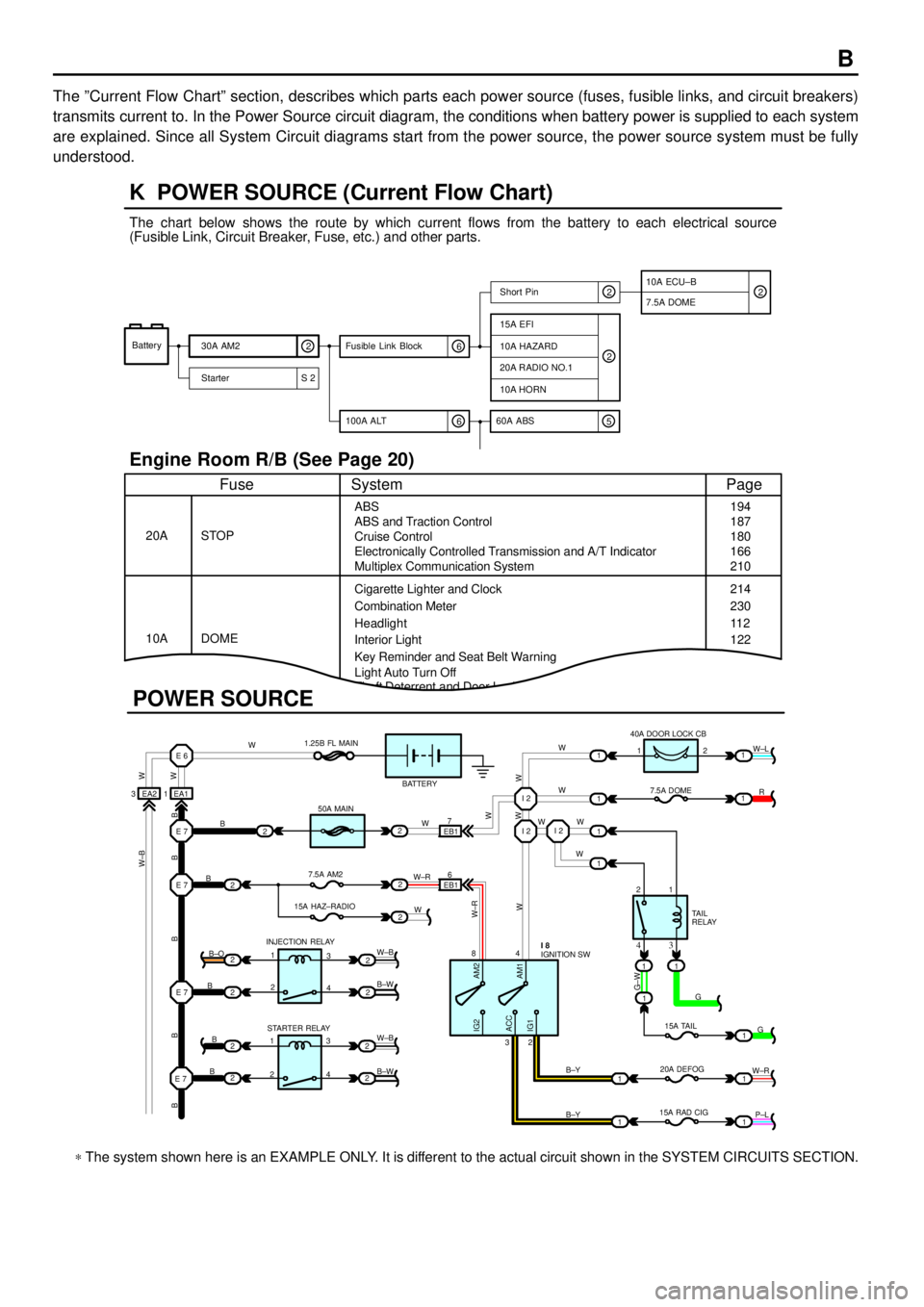
The ºCurrent Flow Chartº section, describes which parts each power source (fuses, fusible links, and circuit breakers)
transmits current to. In the Power Source circuit diagram, the conditions when battery power is supplied to each system
are explained. Since all System Circuit diagrams start from the power source, the power source system must be fully
understood.
Theft Deterrent and Door Lock Control
K POWER SOURCE (Current Flow Chart)
11
1
EA1 1EA2 3
7
EB16
E 6
E 7I 2I 2
I 2
E 7
E 7
E 7
2
1
1
2
2
2
2
2
B
B
W W
B B B B BW±B
B
B
B B±O
B±W
W±B
B±W STARTER RELAY INJECTION RELAY15A HAZ±RADIO7.5A AM250A MAIN 1.25B FL MAIN
BATTERY
WWW
W W W
R W±L
W
W
G±W
G
15A TAIL
20A DEFOG
15A RAD CIGTA I L
RELAY 7.5A DOME 40A DOOR LOCK CB
2 1
1 2
4 8
2 3
3 4
G
W±R
P±L B±Y
B±Y
W±R
AM2 IG2
ACC
IG1AM1W W
W±R
W W
W±B
21
1
1
1
1
2
2
2
2
3
4
3
4 1
2
1
22
1
11
1
IGNITION SW I 8
Battery
30A AM2
2
Starter S 220A RADIO NO.1
10A HORN
15A EFI
7.5A DOMEShort Pin
10A HAZARD
The chart below shows the route by which current flows from the battery to each electrical source
(Fusible Link, Circuit Breaker, Fuse, etc.) and other parts.
Engine Room R/B (See Page 20)
ABS
ABS and Traction Control
Cruise Control
Electronically Controlled Transmission and A/T Indicator
Multiplex Communication System
Cigarette Lighter and Clock
Key Reminder and Seat Belt Warning STOP
Fuse Page
194
214
11 2
System
DOME 20A
10ACombination Meter
Headlight
Interior Light
2
2
6 100A ALT
EB1
POWER SOURCE
Light Auto Turn Off187
180
166
210
230
122
10A ECU±B
5 60A ABS
2
6 Fusible Link Block2
* The system shown here is an EXAMPLE ONLY. It is different to the actual circuit shown in the SYSTEM CIRCUITS SECTION.
Page 1176 of 4770
G
Position of Parts in Engine Compartment
[1MZ±FE]
I 1 Idle Air Control Valve
I 2 Igniter
I 5 Ignition Coil No.1
I 6 Ignition Coil No.2
I 7 Ignition Coil No.3
I 8 Injector No.1
I 9 Injector No.2
I 10 Injector No.3
I 11 Injector No.4
I 12 Injector No.5
I 13 Injector No.6
K 1 Knock Sensor 1
K 2 Knock Sensor 2
M 2 Mass Air Flow Meter
N 1 Noise Filter (Ignition)
O 1 Oil Pressure SW
P 1 Park/Neutral Position SW,A/T Indicator Light SW and
Back±Up Light SW
P 2 Power Steering Oil Pressure SWR 1 Radiator Fan Motor
S 1 Starter
S 2 Starter
T 1 Theft Deterrent Horn
T 2 Throttle Position Sensor
V 2 Vehicle Speed Sensor (Combination Meter)
V 3 Vehicle Speed Sensor
(Electronically Controlled Transmission)
V 4 VSV (EGR)
V 5 VSV (EVAP)
V 6 VSV (Intake Air Control)
W 1 Washer Level Warning SW
W 2 Washer Motor
W 3 Water Temp. Sender
W 4 Water Temp. SW No.1
W 5 Water Temp. SW No.2
Page 1178 of 4770
G
Position of Parts in Engine Compartment
[5S±FE]
I 1 Idle Air Control Valve
I 3 Ignition Coil and Igniter No.1
I 4 Ignition Coil and Igniter No.2
I 8 Injector No.1
I 9 Injector No.2
I 10 Injector No.3
I 11 Injector No.4
I 14 Intake Air Temp. Sensor
K 1 Knock Sensor 1
M 1 Manifold Absolute Pressure Sensor
N 1 Noise Filter (Ignition)
O 1 Oil Pressure SW
P 1 Park/Neutral Position SW,A/T Indicator Light SW and
Back±Up Light SW
P 2 Power Steering Oil Pressure SWR 1 Radiator Fan Motor
S 1 Starter
S 2 Starter
T 1 Theft Deterrent Horn
T 2 Throttle Position Sensor
V 2 Vehicle Speed Sensor (Combination Meter)
V 4 VSV (EGR)
V 5 VSV (EVAP)
W 1 Washer Level Warning SW
W 2 Washer Motor
W 3 Water Temp. Sender
W 4 Water Temp. SW No.1
Page 1198 of 4770
1230A POWER
1240A DEF
12
40A AM1 1B4
1B1
1K2
1K6
1K1
1K3
1K4
1K5
1B5
2
221J7
2
2
2
22
2 AM1
AM2 7 23
6 ACC
IG1
IG2
ST24
8I 1
12
IG 12
13 25A DOOR
15A STOP
7. 5A OBDTAI LL IGHT REL AY10A TAIL
7. 5A PANEL
POWER RELAY
NOISE FILTER
NOISE FILTER
DEFOGGER RELAY
10A MIRROR±HEATER
15A CIG
7. 5A RAD±NO. 2
15A POWER±OUTLET
15A ECU±IG
10A HEATER
10A GAUGE
25A WIPER
7. 5A TURN
5A IGN
5A STARTER
5A DRL NO. 2
DIM
RELAY10A H±LP RH (
LWR)
10A H±LP LH (
LWR)
JUNCTION
CONNECTOR IGNITION SW I16
J11 B±R
B±R
W B±R
W± B
L±R
B±Y
B±R
R1
1 5
1
5
1
5
13
2
3
2
2
2
3
2
* 1 : TMC MADE
* 2 : TMMK MADE
* 3 : EXCEPT TAIWAN* 4 : W/ TRACTION CONTROL
* 5 : W/ O TRACTI ON CONTROL W±R
R
R±L W±R
(
*8)
(
*8)14
2
3W±R
R±B
R±L(
*8)
R±YR±G
R
A
W±B
1A6
B±R
R
* 6 : CALIFORNIA* 7 : TMC MADE EXCEPT 5S±FE W/O ABS
* 8 : W/ DAYTIME RUNNING LIGHT
* 9 : W/O DAYTIME RUNNING LIGHT
Page 1201 of 4770
STARTING AND IGNITION (1MZ±FE)
2L 4
2A 1
IG M 1
B1
B±RB±R
B±G
B±RB
IGNITION SW
32 51
30A
AM2ST
RELAY
PARK/NEUTRAL
POSITION SW
BATTERY FL MAI N
3. 0WI16
P 1
AP
N5
6 2D 52K92J11 40A
MAIN 76
8 AM2 AM1ACC
IG1
ST1
IG2
ST2
5A
ST ARTER
1J 31K 4
1B 51K 5
W± R
2B 3
JUNCTION
CONNECTOR J1 1
W±B
B
AB
BB±W
GR(
*1) B
GR(
*1 A/T)
GR
B±WW±R
B±R
(
A/T)
JUNCTION
CONNECTOR J29
C 1
B C A 1
A BAB 1K3
1C8
II2 11
2 1
II2 10
B±O(
*2) R
B±W
GR(
*1)
B±O(
*2)
B±O B±W GR(
*1) B±O(
*2)
W±B
B±O(
*2 M/T)(
M/T)
(
*2 A/T)CLUTCH START S W C 7
B±W
(
A/T)
1 2
J 7
JUNCTION
CONNECTORB A, J 8
S 1
STARTERA B, S 2 F 4
FUSIBLE LINK
BLOCKC A, F 6
B C
(
A/T) GR
(
*1 M/T)
B±W
Page 1203 of 4770

STARTING AND IGNITION (1MZ±FE)
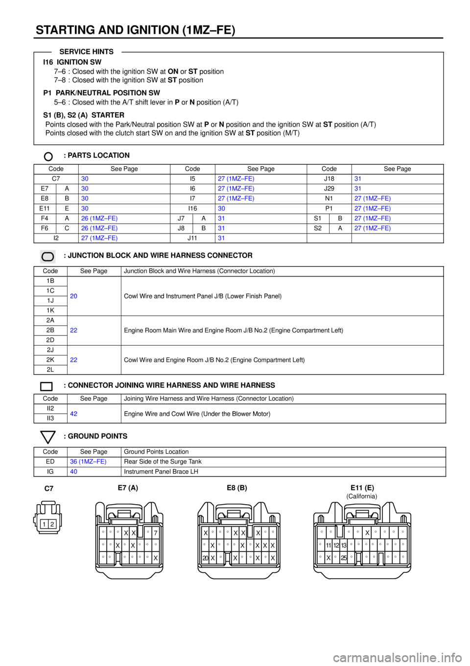
I16 IGNITION SW
7±6 : Closed with the ignition SW at ON or ST position
7±8 : Closed with the ignition SW at ST position
P1 PARK/NEUTRAL POSITION SW
5±6 : Closed with the A/T shift lever in P or N position (A/T)
S1 (B), S2 (A) STARTER
Points closed with the Park/Neutral position SW at P or N position and the ignition SW at ST position (A/T)
Points closed with the clutch start SW on and the ignition SW at ST position (M/T)
: PARTS LOCATION
CodeSee PageCodeSee PageCodeSee Page
C730I527 (1MZ±FE)J1831
E7A30I627 (1MZ±FE)J2931
E8B30I727 (1MZ±FE)N127 (1MZ±FE)
E11E30I1630P127 (1MZ±FE)
F4A26 (1MZ±FE)J7A31S1B27 (1MZ±FE)
F6C26 (1MZ±FE)J8B31S2A27 (1MZ±FE)
I227 (1MZ±FE)J1131
: JUNCTION BLOCK AND WIRE HARNESS CONNECTOR
CodeSee PageJunction Block and Wire Harness (Connector Location)
1B
1C20Cowl Wire and Instrument Panel J/B (Lower Finish Panel)1J20Cowl Wire and Instrument Panel J/B (Lower Finish Panel)
1K
2A
2B22Engine Room Main Wire and Engine Room J/B No.2 (Engine Compartment Left)
2D
gg(g)
2J
2K22Cowl Wire and Engine Room J/B No.2 (Engine Compartment Left)
2L
g(g )
: CONNECTOR JOINING WIRE HARNESS AND WIRE HARNESS
CodeSee PageJoining Wire Harness and Wire Harness (Connector Location)
II242Engine Wire and Cowl Wire (Under the Blower Motor)II342Engine Wire and Cowl Wire (Under the Blower Motor)
: GROUND POINTS
CodeSee PageGround Points Location
ED36 (1MZ±FE)Rear Side of the Surge Tank
IG40Instrument Panel Brace LH
12
���XX 7
��X�X�
�� �X �
��
�� �X��XX�
����XX
20��X X
�X
�X X �
X
X�
X
�
C7E7 (A) E8 (B)
� � � � � �
� � � �13 11
25 X�
��
��
� 12
� �� ��X���� (California)
E11 (E)
SERVICE HINTS
Page 1205 of 4770
STARTING AND IGNITION (5S±FE)
2L 4
2A 1
IG M 1
B1
B±R
B±G
B±RB
IGNITION SW
32 51
30A
AM2ST
RELAY
PARK/NEUTRAL
POSITION SW
BATTERY FL MAI N
3. 0WI16
P 1
AP
N5
6 2D 52K92J11 40A
MAIN 76
8 AM2 AM1ACC
IG1
ST1
IG2
ST2
5A
ST ARTER
1J 31K 4
1B 51K 5
W± R
2B 3
JUNCTION
CONNECTOR J1 1
W±B
B
AB
BB±W
GR(
*3) B
GR(
*3 A/T)
GR
B±WW±R
(
A/T)
JUNCTION
CONNECTOR J29
C 1
B C A 1
A BABII2 11
2 1
II2 10
B±O(
*4) RB±W
GR(
*3)
B±O(
*4)
B±O B±W GR(
*3) B±O(
*4)
W±B
B±O(
*4 M/T)(
M/T)
(
*4 A/T)CLUTCH START SW C 7
B±W
(
A/T)
1 2
J 7
JUNCTION
CONNECTORB A, J 8
S 1
STARTERA B, S 2 F 4
FUSIBLE LINK
BLOCKC A, F 6B±RB±R
II3 13
B±R
B C
GR
(
*3 M/T)
(
A/T)
B±W