Page 1803 of 4770
AUTOMATIC TRANSAXLEPREPARATION ±
AX±7
(09351±32100)Drive Pinion Bearing Replacer
(09351±32120)Overdrive Bearing Replacer
(09351±32140)Oil Seal Replacer
(09351±32150)Oil Seal Replacer
(09351±32190)Measure Terminal
(09351±32200)No.3 Piston Spring Compressor
09608±16011Rear Hub Bearing Tool±Remove differential side bearing
09612±65014Steering Worm Bearing PullerRemove pinion shaft bearing outer
race
09950±40010Puller B Set
RECOMMENDED COOL
09031±00030Pin Punch .
AX02M±02
Page 1829 of 4770

AUTOMATIC TRANSAXLECOMPONENT PARTS REMOVAL ±
AX±33
GENERAL NOTES
The instructions here are organized so that you work on only one component group at a time.
This will help avoid confusion from similar±looking parts of different subassemblies being on your work-
bench at the same time.
The component groups are inspected and repaired from the converter housing side.
As much as possible, complete the inspection, repair and assembly before proceeding to the next compo-
nent group. If a component group cannot be assembled because parts are being ordered, be sure to keep
all parts of that group in a separate container while proceeding with disassembly, inspection, repair and
assembly of other component groups.
Recommended fluid for the automatic transaxle: ATF D±@@@@@: [g 2] or DEXRON®@@@@@: [g
3](DEXRON®@@@@@: [g 2])
1. GENERAL CLEANING NOTES:
(a) All disassembled parts should be washed clean and any fluid passages and holes blown through with
compressed air.
(b) When using compressed air to dry parts, always aim away from yourself to prevent accidentally spray-
ing automatic transaxle fluid or kerosene in your face.
(c) The recommended automatic transaxle fluid or kerosene should be used for cleaning.
2. PARTS ARRANGEMENT:
(a) After cleaning, the parts should be arranged in the correct order to allow efficient inspection, repairs,
and reassembly.
(b) When disassembling a valve body, be sure to keep each valve together with the corresponding spring.
(c) New brakes and clutches that are to be used for replacement must be soaked in transaxle fluid for at
least fifteen minutes before assembly.
3. GENERAL ASSEMBLY:
(a) All oil seal rings, clutch discs, clutch plates, rotating parts, and sliding surfaces should be coated with
transmission fluid prior to reassembly.
(b) All gaskets and rubber O±rings should be replaced.
(c) Make sure that the ends of a snap ring are not aligned with one of the cutouts and are installed in the
groove correctly.
(d) If a worn bushing is to be replaced, the subassembly containing that bushing must be replaced.
(e) Check thrust bearings and races for wear or damage. Replace if necessary.
(f) Use petroleum jelly to keep parts in place.
AX02T±07
Page 2350 of 4770
CO067±03
Z18990
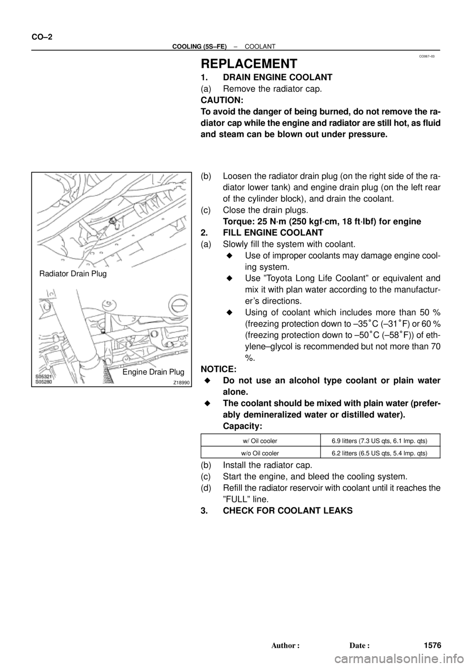
Radiator Drain Plug
Engine Drain Plug CO±2
± COOLING (5S±FE)COOLANT
1576 Author�: Date�:
REPLACEMENT
1. DRAIN ENGINE COOLANT
(a) Remove the radiator cap.
CAUTION:
To avoid the danger of being burned, do not remove the ra-
diator cap while the engine and radiator are still hot, as fluid
and steam can be blown out under pressure.
(b) Loosen the radiator drain plug (on the right side of the ra-
diator lower tank) and engine drain plug (on the left rear
of the cylinder block), and drain the coolant.
(c) Close the drain plugs.
Torque: 25 N´m (250 kgf´cm, 18 ft´lbf) for engine
2. FILL ENGINE COOLANT
(a) Slowly fill the system with coolant.
�Use of improper coolants may damage engine cool-
ing system.
�Use ºToyota Long Life Coolantº or equivalent and
mix it with plan water according to the manufactur-
er's directions.
�Using of coolant which includes more than 50 %
(freezing protection down to ±35°C (±31°F) or 60 %
(freezing protection down to ±50°C (±58°F)) of eth-
ylene±glycol is recommended but not more than 70
%.
NOTICE:
�Do not use an alcohol type coolant or plain water
alone.
�The coolant should be mixed with plain water (prefer-
ably demineralized water or distilled water).
Capacity:
w/ Oil cooler6.9 litters (7.3 US qts, 6.1 lmp. qts)
w/o Oil cooler6.2 litters (6.5 US qts, 5.4 lmp. qts)
(b) Install the radiator cap.
(c) Start the engine, and bleed the cooling system.
(d) Refill the radiator reservoir with coolant until it reaches the
ºFULLº line.
3. CHECK FOR COOLANT LEAKS
Page 2513 of 4770
A00434
± DIAGNOSTICSENGINE (5S±FE)
DI±93
328 Author�: Date�:
2 Check spark plug and spark of misfiring cylinder.
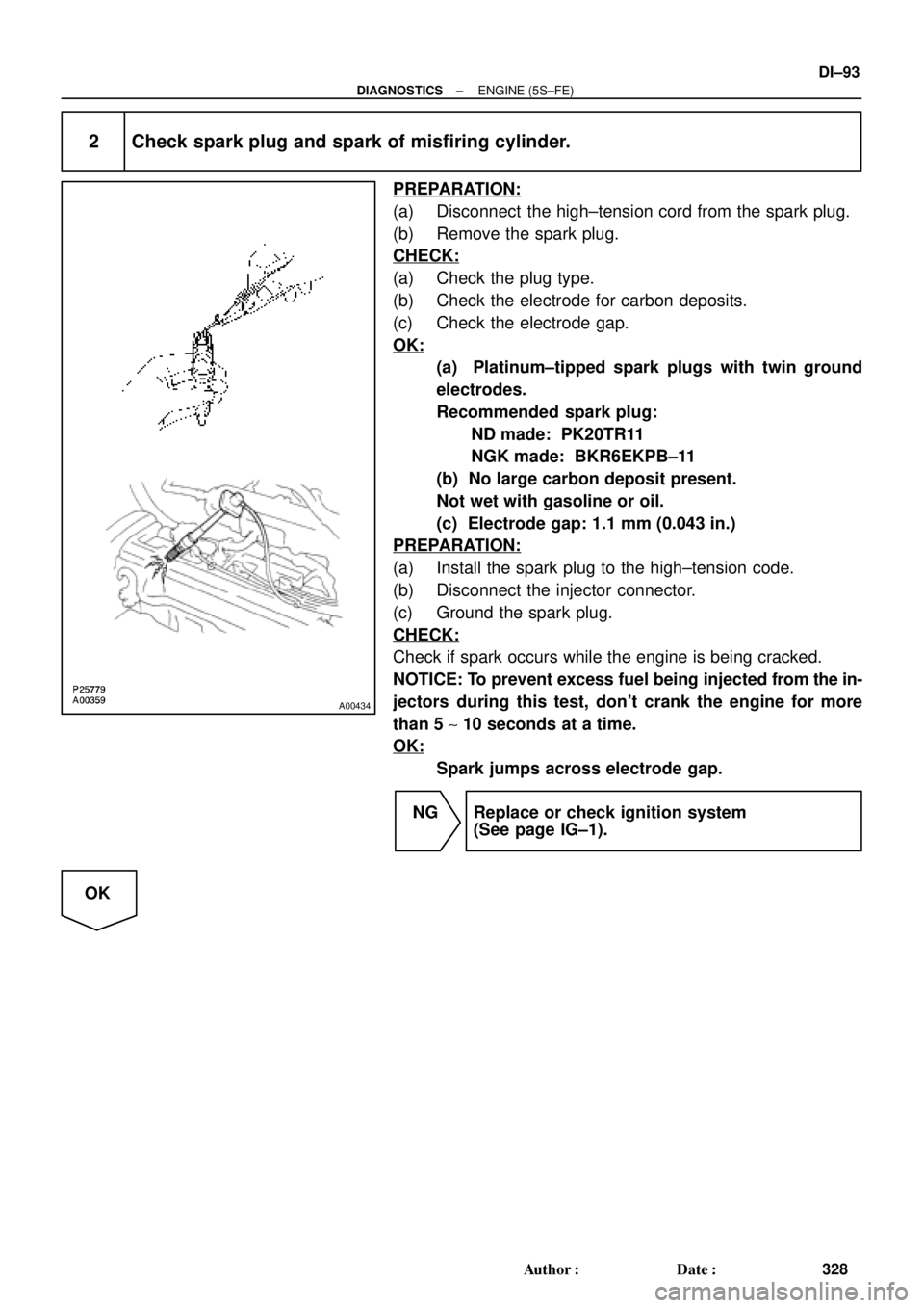
PREPARATION:
(a) Disconnect the high±tension cord from the spark plug.
(b) Remove the spark plug.
CHECK:
(a) Check the plug type.
(b) Check the electrode for carbon deposits.
(c) Check the electrode gap.
OK:
(a) Platinum±tipped spark plugs with twin ground
electrodes.
Recommended spark plug:
ND made: PK20TR11
NGK made: BKR6EKPB±11
(b) No large carbon deposit present.
Not wet with gasoline or oil.
(c) Electrode gap: 1.1 mm (0.043 in.)
PREPARATION:
(a) Install the spark plug to the high±tension code.
(b) Disconnect the injector connector.
(c) Ground the spark plug.
CHECK:
Check if spark occurs while the engine is being cracked.
NOTICE: To prevent excess fuel being injected from the in-
jectors during this test, don't crank the engine for more
than 5 ~ 10 seconds at a time.
OK:
Spark jumps across electrode gap.
NG Replace or check ignition system
(See page IG±1).
OK
Page 2699 of 4770
A00221P25779
P23917
± DIAGNOSTICSENGINE (1MZ±FE)
DI±279
514 Author�: Date�:
2 Check spark plug and spark of misfiring cylinder.
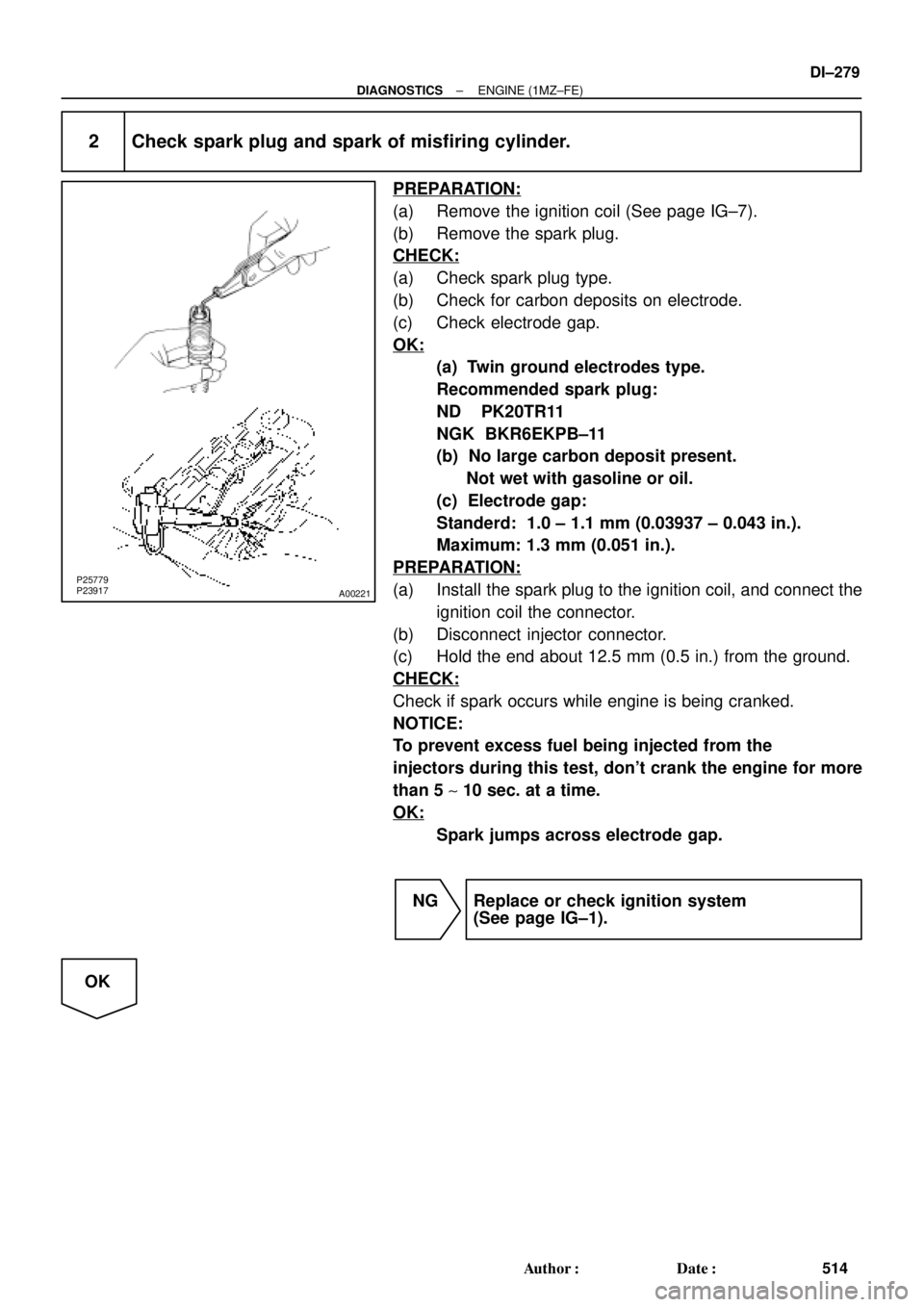
PREPARATION:
(a) Remove the ignition coil (See page IG±7).
(b) Remove the spark plug.
CHECK:
(a) Check spark plug type.
(b) Check for carbon deposits on electrode.
(c) Check electrode gap.
OK:
(a) Twin ground electrodes type.
Recommended spark plug:
ND PK20TR11
NGK BKR6EKPB±11
(b) No large carbon deposit present.
Not wet with gasoline or oil.
(c) Electrode gap:
Standerd: 1.0 ± 1.1 mm (0.03937 ± 0.043 in.).
Maximum: 1.3 mm (0.051 in.).
PREPARATION:
(a) Install the spark plug to the ignition coil, and connect the
ignition coil the connector.
(b) Disconnect injector connector.
(c) Hold the end about 12.5 mm (0.5 in.) from the ground.
CHECK:
Check if spark occurs while engine is being cranked.
NOTICE:
To prevent excess fuel being injected from the
injectors during this test, don't crank the engine for more
than 5 ~ 10 sec. at a time.
OK:
Spark jumps across electrode gap.
NG Replace or check ignition system
(See page IG±1).
OK
Page 3543 of 4770
P12710
O±Ring
A01816
P12811Align Intake
P12871
Main Gear
Sub±Gear
Service Bolt Intake
± ENGINE MECHANICAL (1MZ±FE)CYLINDER HEAD
EM±37
1323 Author�: Date�:
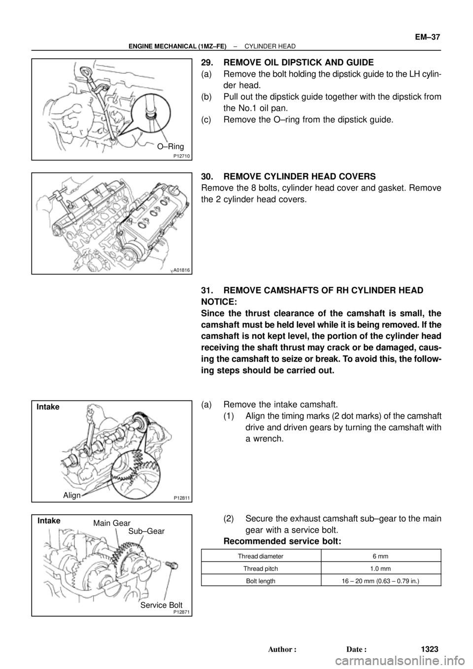
29. REMOVE OIL DIPSTICK AND GUIDE
(a) Remove the bolt holding the dipstick guide to the LH cylin-
der head.
(b) Pull out the dipstick guide together with the dipstick from
the No.1 oil pan.
(c) Remove the O±ring from the dipstick guide.
30. REMOVE CYLINDER HEAD COVERS
Remove the 8 bolts, cylinder head cover and gasket. Remove
the 2 cylinder head covers.
31. REMOVE CAMSHAFTS OF RH CYLINDER HEAD
NOTICE:
Since the thrust clearance of the camshaft is small, the
camshaft must be held level while it is being removed. If the
camshaft is not kept level, the portion of the cylinder head
receiving the shaft thrust may crack or be damaged, caus-
ing the camshaft to seize or break. To avoid this, the follow-
ing steps should be carried out.
(a) Remove the intake camshaft.
(1) Align the timing marks (2 dot marks) of the camshaft
drive and driven gears by turning the camshaft with
a wrench.
(2) Secure the exhaust camshaft sub±gear to the main
gear with a service bolt.
Recommended service bolt:
Thread diameter6 mm
Thread pitch1.0 mm
Bolt length16 ± 20 mm (0.63 ± 0.79 in.)
Page 3545 of 4770
P12873Main Gear
Sub±GearService Bolt Intake
P12958
Intake
7
85
6
3
41
2
9
10
P12886
7
85 6
3 41 2
9 10 Exhaust
P12596
± ENGINE MECHANICAL (1MZ±FE)CYLINDER HEAD
EM±39
1325 Author�: Date�:
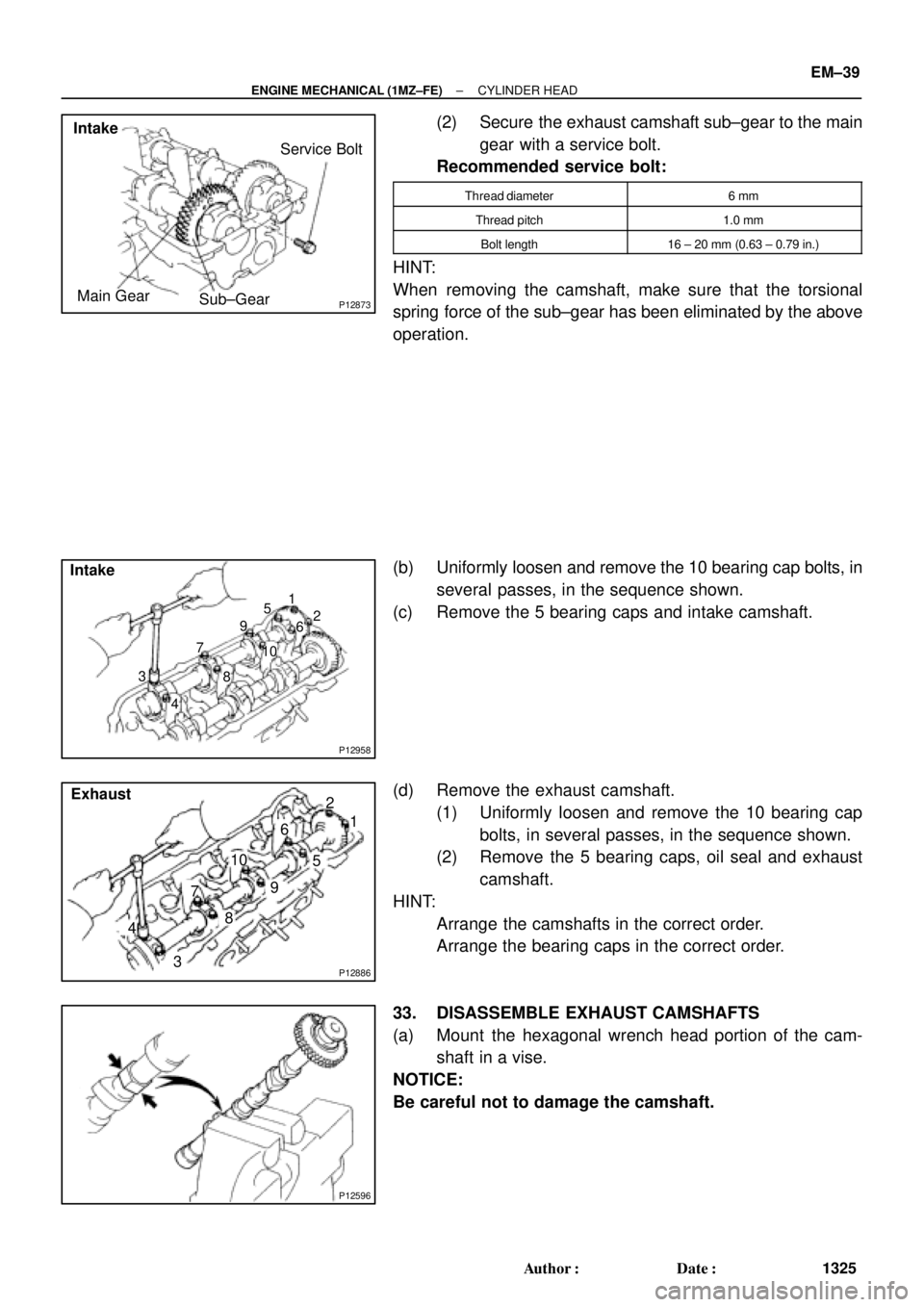
(2) Secure the exhaust camshaft sub±gear to the main
gear with a service bolt.
Recommended service bolt:
Thread diameter6 mm
Thread pitch1.0 mm
Bolt length16 ± 20 mm (0.63 ± 0.79 in.)
HINT:
When removing the camshaft, make sure that the torsional
spring force of the sub±gear has been eliminated by the above
operation.
(b) Uniformly loosen and remove the 10 bearing cap bolts, in
several passes, in the sequence shown.
(c) Remove the 5 bearing caps and intake camshaft.
(d) Remove the exhaust camshaft.
(1) Uniformly loosen and remove the 10 bearing cap
bolts, in several passes, in the sequence shown.
(2) Remove the 5 bearing caps, oil seal and exhaust
camshaft.
HINT:
�Arrange the camshafts in the correct order.
�Arrange the bearing caps in the correct order.
33. DISASSEMBLE EXHAUST CAMSHAFTS
(a) Mount the hexagonal wrench head portion of the cam-
shaft in a vise.
NOTICE:
Be careful not to damage the camshaft.
Page 3650 of 4770

S05308
16 mm Plug
Wrench
P20584
IG0152
B06373
Ohmmeter
± IGNITION (5S±FE)IGNITION SYSTEM
IG±3
1685 Author�: Date�:
(c) Using a 16 mm plug wrench, remove the 4 spark plugs.
(d) Visually check the spark plug for thread damage and insu-
lator damage.
If abnormal, replace the spark plug.
Recommended spark plug:
DENSO madePK20TR11
NGK madeBKR6EKPB11
(e) Inspect the electrode gaps.
Maximum electrode gap for used spark plug:
1.3 mm (0.051 in.)
If the gap is greater than maximum, replace the spark plug.
Correct electrode gap for new spark plug:
1.1 mm (0.043 in.)
NOTICE:
If adjusting the gap of a new spark plug, bend only the base
of the ground electrode. Do not touch the tip. Never attempt
to adjust the gap on the used plug.
(f) Clean the spark plugs.
If the electrode has traces of wet carbon, allow it to dry and then
clean with a spark plug cleaner.
Air pressure: Below 588 kPa (6 kgf/cm
2, 85 psi)
Duration: 20 seconds or less
HINT:
If there are traces of oil, remove it with gasoline before using the
spark plug cleaner.
(g) Using a 16 mm plug wrench, install the 4 spark plugs.
Torque: 18 N´m (180 kgf´cm, 13 ft´lbf)
(h) Reconnect the high±tension cords from the spark plugs.
4. INSPECT IGNITION COILS WITH IGNITERS
(a) Disconnect the high±tension cords from the ignition coils.
(b) Inspect the secondary coil resistance.
Using an ohmmeter, measure the resistance between the
high±tension terminals.
Secondary coil resistance:
Cold9.7 ± 16.7 kW
Hot12.4 ± 19.6 kW