Page 88 of 4770
17. INSTALL ENGINE MOVING CONTROL ROD
(a) Temporarily install the engine moving control rod with
the 3 bolts in the sequence shown. 15. INSTALL NO.2 ENGINE MOUNTING BRACKET
(a) Temporarily install the No.2 engine mounting bracket
with the 2 bolts. 14. INSTALL SPARK PLUGS
(a) Using a 16 mm plug wrench, install the spark plug.
(b) Connect the high±tension cords.
(b) Install the remaining bolt.
(c) Tighten the 3 bolts in the sequence shown.
Torque: 52 N±m (530 kgf±cm, 38 ft±lbf)
16. CONNECT CONNECTOR TO GROUND WIRE ON RH
FENDER APRON
± 5S±FE ENGINEENGINE MECHANICALEG1±38
Page 102 of 4770

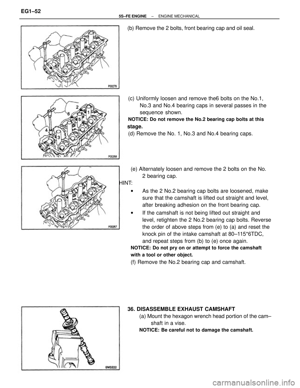
(e) Alternately loosen and remove the 2 bolts on the No.
2 bearing cap.
HINT:
wAs the 2 No.2 bearing cap bolts are loosened, make
sure that the camshaft is lifted out straight and level,
after breaking adhesion on the front bearing cap.
wIf the camshaft is not being lifted out straight and
level, retighten the 2 No.2 bearing cap bolts. Reverse
the order of above steps from (e) to (a) and reset the
knock pin of the intake camshaft at 80±115*6TDC,
and repeat steps from (b) to (e) once again.
NOTICE: Do not pry on or attempt to force the camshaft
with a tool or other object.
(f) Remove the No.2 bearing cap and camshaft. (c) Uniformly loosen and remove the6 bolts on the No.1,
No.3 and No.4 bearing caps in several passes in the
sequence shown.
NOTICE: Do not remove the No.2 bearing cap bolts at this
stage.
(d) Remove the No. 1, No.3 and No.4 bearing caps.
36. DISASSEMBLE EXHAUST CAMSHAFT
(a) Mount the hexagon wrench head portion of the cam±
shaft in a vise.
NOTICE: Be careful not to damage the camshaft.
(b) Remove the 2 bolts, front bearing cap and oil seal.
± 5S±FE ENGINEENGINE MECHANICALEG1±52
Page 118 of 4770
2. INSTALL SPARK PLUG TUBES
(a) Clean the cylinder head tube holes of any residua!
adhesive, oil or foreign particles. Remove any oil with
kerosene or gasoline.
(b) Screw the threads of the spark plug tube coated with
adhesive into the cylinder head.
(c) Using the spark plug tube nut and a 30 mm socket
wrench, tighten the spark plug tubes.
Torque: 39 N±m (400 kgf±cm, 29 ft±lbf)
(b) Install the following parts:
(1) Camshaft gear spring
(2) Camshaft sub gear
(3) Wave washer
HINT: Align the pins on the gears with the spring ends.(d) Retighten the cylinder head bolts 90� in the sequence
shown on the previous page.
(e) Check that the painted mark is now at a 90� angle to
front.
3. ASSEMBLY EXHAUST CAMSHAFT
(a) Mount the hexagon wrench head portion of the cam±
shaft in a vise.
NOTICE: Be careful not to damage the camshaft.
(c) Mark the front of the cylinder head bolt head with
paint.
± 5S±FE ENGINEENGINE MECHANICALEG1±68
Page 139 of 4770

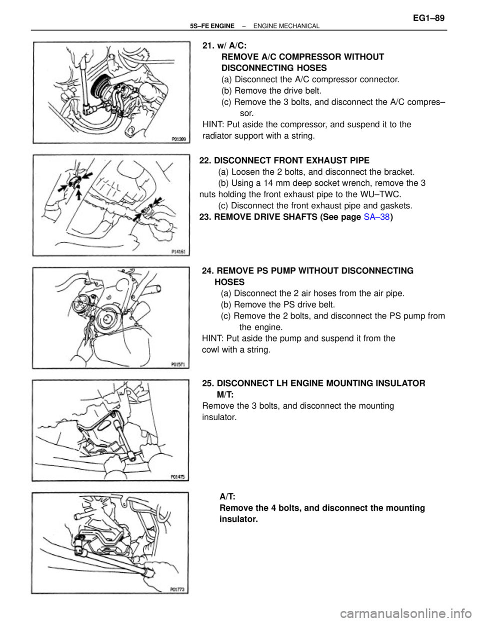
21. w/ A/C:
REMOVE A/C COMPRESSOR WITHOUT
DISCONNECTING HOSES
(a) Disconnect the A/C compressor connector.
(b) Remove the drive belt.
(c) Remove the 3 bolts, and disconnect the A/C compres±
sor.
HINT: Put aside the compressor, and suspend it to the
radiator support with a string.
24. REMOVE PS PUMP WITHOUT DISCONNECTING
HOSES
(a) Disconnect the 2 air hoses from the air pipe.
(b) Remove the PS drive belt.
(c) Remove the 2 bolts, and disconnect the PS pump from
the engine.
HINT: Put aside the pump and suspend it from the
cowl with a string. 22. DISCONNECT FRONT EXHAUST PIPE
(a) Loosen the 2 bolts, and disconnect the bracket.
(b) Using a 14 mm deep socket wrench, remove the 3
nuts holding the front exhaust pipe to the WU±TWC.
(c) Disconnect the front exhaust pipe and gaskets.
23. REMOVE DRIVE SHAFTS (See page SA±38)
25. DISCONNECT LH ENGINE MOUNTING INSULATOR
M/T:
Remove the 3 bolts, and disconnect the mounting
insulator.
A/T:
Remove the 4 bolts, and disconnect the mounting
insulator.
± 5S±FE ENGINEENGINE MECHANICALEG1±89
Page 140 of 4770
30. REMOVE ENGINE AND TRANSAXLE ASSEMBLY
FROM VEHICLE
(a) Lift the engine out of the vehicle slowly and carefully.
NOTICE: Be careful not to hit the PS gear housing or
perk/neutral position switch (A/T).
(b) Make sure the engine is clear of all wiring, hoses and
cables.
(c) Place the engine and transaxle assembly onto the
stand. 26. DISCONNECT RR ENGINE MOUNTING INSULATOR
(a) Remove the hole plugs.
(b) Remove the 3 nuts, and disconnect the mounting
insulator.
27. DISCONNECT FR ENGINE MOUNTING INSULATOR
Remove the 3 bolts, and disconnect the mounting
insulator.
28. ATTACH ENGINE SLING DEVICE TO ENGINE
HANGERS
29. REMOVE ENGINE MOVING CONTROL ROD
Remove the 3 bolts and control rod.
± 5S±FE ENGINEENGINE MECHANICALEG1±90
Page 141 of 4770
31. A/T:
REMOVE STARTER
32. SEPARATE ENGINE AND TRANSAXLE
M/T (See page MX±10)
A/T (See page AX1±21)
34. REMOVE FR ENGINE MOUNTING INSULATOR
(a) Remove the bolt, nut and manifold stay.
(b) Remove the 4 bolts and mounting insulator. 33. REMOVE N0.2 RH ENGINE MOUNTING BRACKET
Remove the 3 bolts and engine mounting bracket.
35. REMOVE RR ENGINE MOUNTING INSULATOR
Remove the 4 bolts and mounting insulator.
± 5S±FE ENGINEENGINE MECHANICALEG1±91
Page 164 of 4770
2. CALCULATE AMOUNT TO BORE CYLINDERS
(a) Using a micrometer, measure the piston diameter at
right angles to the piston pin center line, 23.5 mm
(0.925 in.) from the piston head.
(b) Calculate the amount of each cylinder is to be rebored
as follows:
Size to be rebored = P + C±H
P = Piston diameter
C = Piston clearance
0.14 ± 0.18 mm (0.0055 ± 0.0063 in.)
H = Allowance for honing
0.20 mm (0.0008 in.) or less
3. BORE AND HONE CYLINDER TO CALCULATED
DIMENSIONS
Maximum honing:
0.02 mm (0.0008 in.)
NOTICE: Excess honing will destroy the finished round±
ness.
CYLINDER BORING
HINT:
wBore all the 4 cylinders for the oversized piston
outside diameter.
wReplace all the piston rings with ones to match
the oversized pistons.
1. KEEP OVERSIZED PISTONS
Oversized piston diameter:
O/S 0.50
87.35 ± 87.38 mm (3.4390±3.4402 in.)
± 5S±FE ENGINEENGINE MECHANICALEG1±114
Page 176 of 4770
13. M/T:
INSTALL FLYWHEEL
(a) Apply adhesive to 2 or 3 threads of the mounting bolt
end.
Adhesive:
Part No.08833±00070. THREE BOND 1324 or equi±
valent
14. A/T:
INSTALL DRIVE PLATE (See procedure step 13)
Torque: 83 N±m (850 kgf±cm, 61 ft±lbf)
15. M/T:
INSTALL CLUTCH DISC AND COVER(b) Install the flywheel on the crankshaft.
(c) install and uniformly tighten the mounting bolts in
several passes, in the sequence shown.
Torque: 88 N±m (900 kgf±cm, 66 ft±lbf)
± 5S±FE ENGINEENGINE MECHANICALEG1±126